First companionway, storage boxes on the port side, strengthening ribs and aft superstructure.

Here is the first companionway, as yet without painted edges etc.

Here a couple more pics from different angles (the same companionway)

And here installed in the forward deck, as yet without hatch and wire frame, but with the edges touched up!

Next comes the addition of the strengthening ribs around the inside of the hull ‘walls’, the storage boxes on deck and the aft superstructure, again not yet fitted with its railings – mind your step!

Oh well, the lighting isn’t great, but you get the idea 🙂

For the full report, please go to https://thingummybob.com/modelmaking/building-dom-bumagis-diana/

75mm Gun platform buttresses on deck

The 75mm gun platforms have to be done on the upper deck, which turned out to be a real pain. On all the other models and drawings I have, these outriggers are drawn and constructed as a plain buttress, without reverse curves at the sides. Take a look at the pics and you will see what I mean. Definitely a challenge to build – at least the aft ones only have one side with the reversed curves.

Here is a construction series of that rear one, to show the difference between the straight and the curved side (huge magnification, about 4x life Size?)

And now with the ‘wing’ formed and stuck down from the inside and out.

And how it fits on the starboard side, prior to fitting the tubes through to the portholes and prior to touching up the white edges:

Now the other side is also done!

Slowly, slowly I move forwards. Our baby is due in a few weeks, so I’d better get on with it!

For the full report, please go to https://thingummybob.com/modelmaking/building-dom-bumagis-diana/

Hull sides and Hawes pipes, anchor positions as mounted

Ok, so the port side is now on, after a load of trimming and adjustment, but despite that, looks quite good, if not exactly perfect:

One of the storage bins (at huge magnification), which I decided to have a trial at building, despite there not being any help or diagrams from the instructions – I had to resort to the internet to have an idea how they really looked:

Having fitted the forward portion of the hull next to the forward deck, I also wanted to test the fit of the bulges which house the mounts of the Canet 152mm/45cal. Guns. It was not bad, but did need to be ‘modified’. However, I believe that was in part to my slightly oversize deck portion that stuck out. We will see, as all the others have now been trimmed to size! Amazing what half a millimetre can do! Difficult is the double curve aft, where the bulge ‘merges’ into the side. Next time, I’ll also bevel the inside edges to get a smoother transition 🙂 At a ‘normal’ distance, it still looks pretty good, though:

Here the whole starboard side showing all the installed gun ‘pods’

The inside of the starboard side showing the Hawse pipe, but before the glazing and the bars on the front portholes.

Those sides have now been glazed and the bars on the forward portholes near the anchor have been added, too. Tomorrow the wires on the hatches for the aft gun will be added, the rest of the gun mounts will be fitted below deck and maybe the starboard sides of the hull will be glued in place!

Now the same from the seen side!

And completed without cover on the Hawes but reinforcements for the Anchors and the Hawes built up

Still a bit of touching up to do on the hull where the waterline meets the sides.

Through the portals you can see the gun-mounts waiting for the barrels to be fitted, when it is ‘safe’ to do so!

For the full report, please go to https://thingummybob.com/modelmaking/building-dom-bumagis-diana/

75mm Canet guns, Hull sides glazing and detailing before fitting including Hawes build

Work on the 75mm guns has begun, but I’m still not completely satisfied. The drawings from the instructions are not very conclusive, but I assume that they don’t expect any greater need for detail; but if they include parts, it should at least be clear where they go and how they look when finished: That goes for a lot of the drawings, which out of economy of space, the reverse side of many views is omitted, leaving the builder to fantasize where the parts go, even if they are different to the side shown in the (very good) drawings. Here a few pics of work in progress and one of the reference pictures I found.


Excellent diagrams from their kit – which, however, leave a few questions:

My first efforts at the 75mm at huge magnification:

Here a later pic of work in progress on the Canet 75mm guns intended for inside the ship behind the hatches in the side. I am getting a bit of practice in for the ‘proper’ ones which will be on full display for the upper deck. Note the change in shape of the cradle for the barrel in the bottom picture, being closer to the archive photo of the gun above … Here unmounted and the edges unpainted.

Lots of detail to refine before I will be satisfied for the guns that will be fully visible on deck! 🙂

So, the hull sides also have to have quite a bit of work done on them before fitting to the carcass: The gun recesses at the aft and the recess behind each anchor, for example. There are various other jobs in sight. I want to cut out the portholes and ‘glaze’ them. I was going to fit brass surrounds, but they are a bit garish, so I opted for gold paint instead 🙂

There are a pair of portholes for each anchor which have bars over them…

… Which I made from 0.1mm copper wire stripped out of some electrical leads and blackened with a permanent marker. Holes were pierced in the card with a sharpened needle and the wires threaded through, pulled taut and glued from the back, same as was done for the ‘risers’ for the hatches for the aft most gun, seen below on the right.


Here are the mid ships gun mounts positioned in their places in the port hull , prior to fitting the sides. I put them in now, as they wouldn’t fit through the hatches afterwards. I don’t want to fit the barrels yet, as they would make the fitting of the hull sides more difficult to do without damaging them. The black spots will end up behind where the portholes will be afterwards…

Another detail I decided to add is the Hawse pipe, as seen in the picture below: The Hawse hole on these ships is built up outside the hull and will be added later.


As work progresses, the bench tends gets more cluttered and has to be cleared again to move on to the next section of the work…

For the full report, please go to https://thingummybob.com/modelmaking/building-dom-bumagis-diana/

Diana Decking entirely of real wood planking…

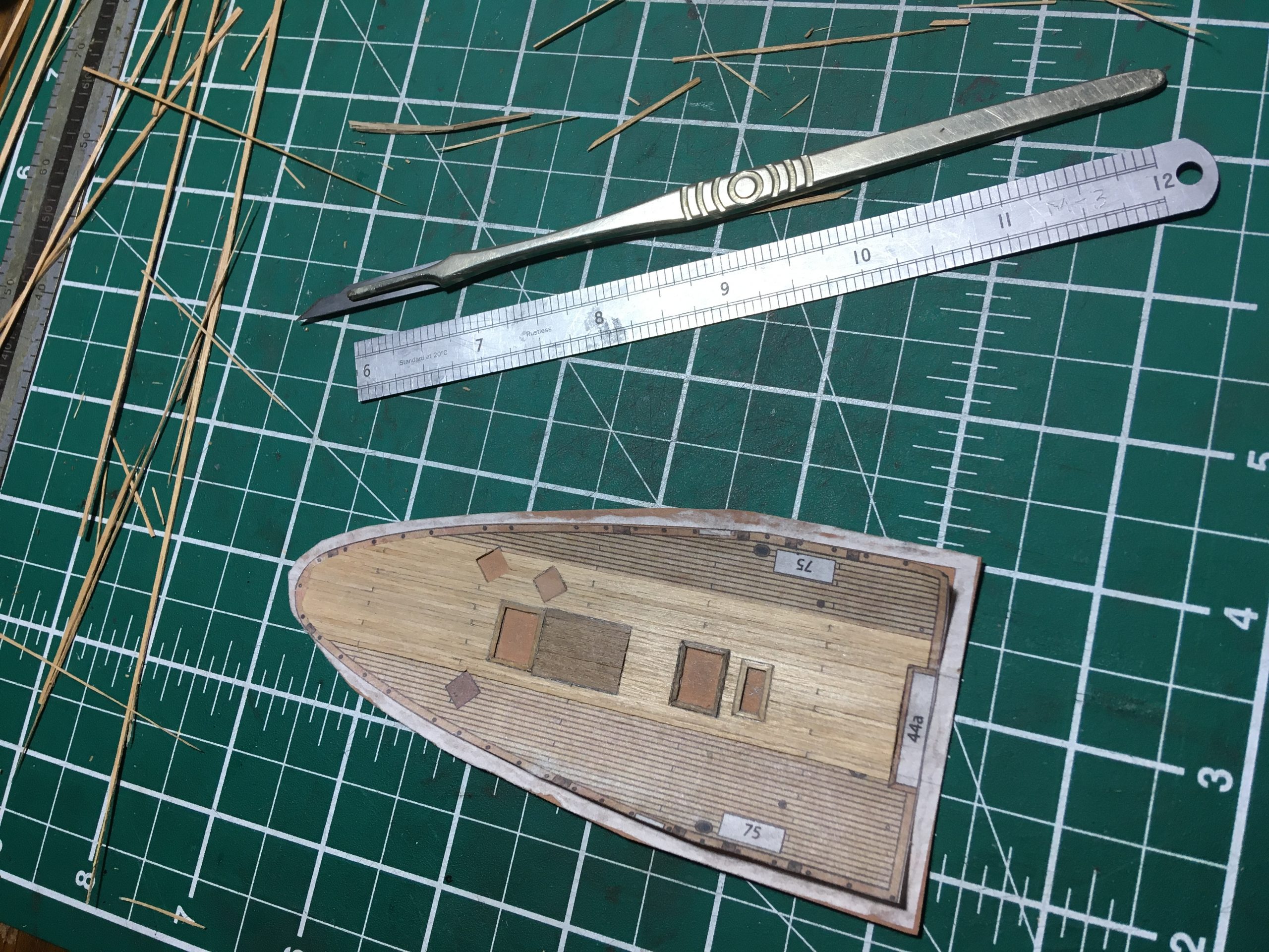
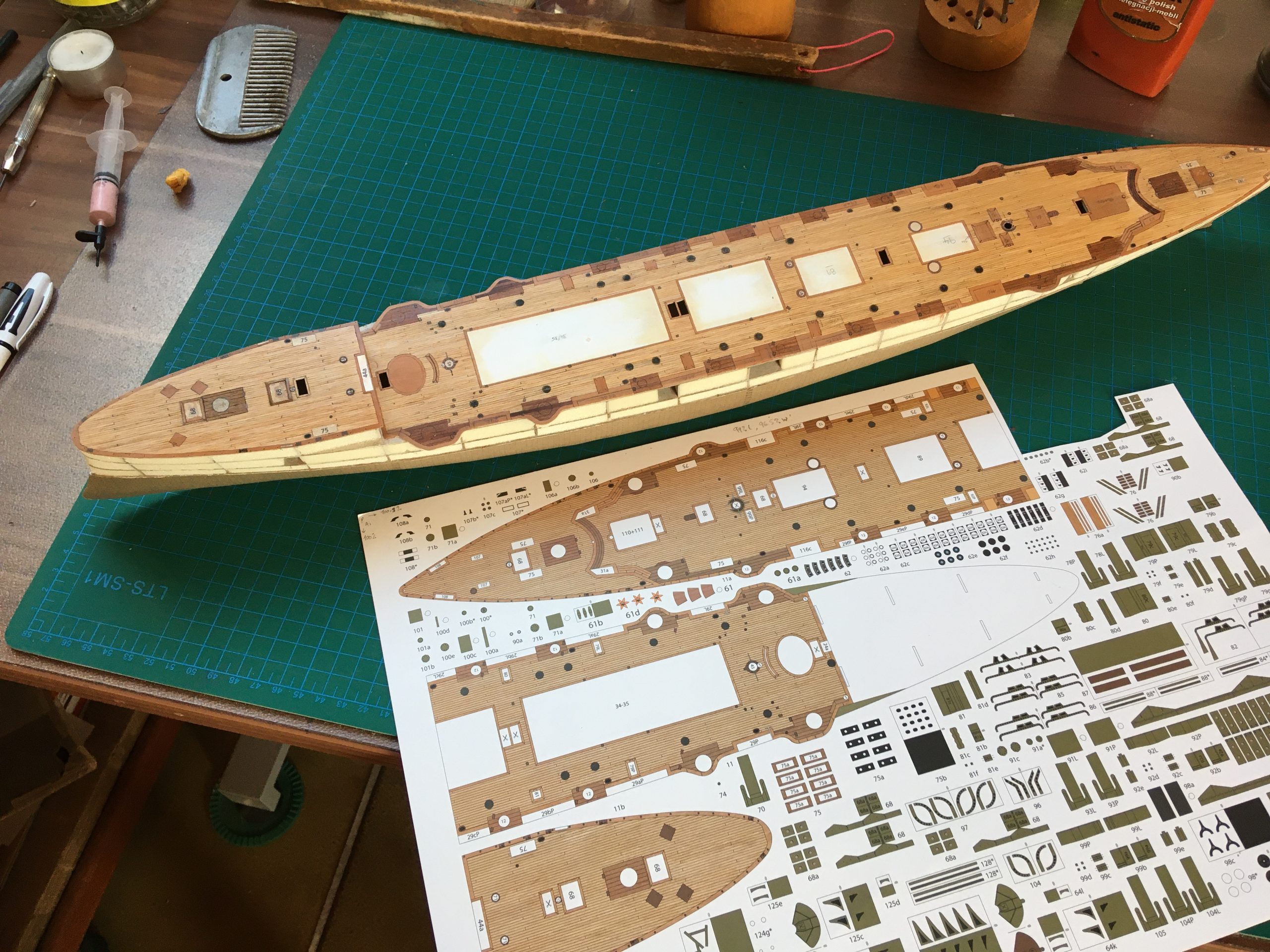
I made the decision again to do the deck in real wood, planked as the original, like some of the other ships I have done – to me it really is worth the trouble. I still had some very thin veneer of the right sort and set about cutting strips about 0.7mm wide in preparation for the bow-deck. Here the deck is started, a sharp scalpel and ruler for cutting and placing the planks. A razor was used to cut the strips, the scalpel is used to cut them to length as I glue them to the reference base – a scan of the original checked for size (VERY important, as scanners and printers do the strangest things to proportions!) and printed out on very thin typewriter-copy-paper.

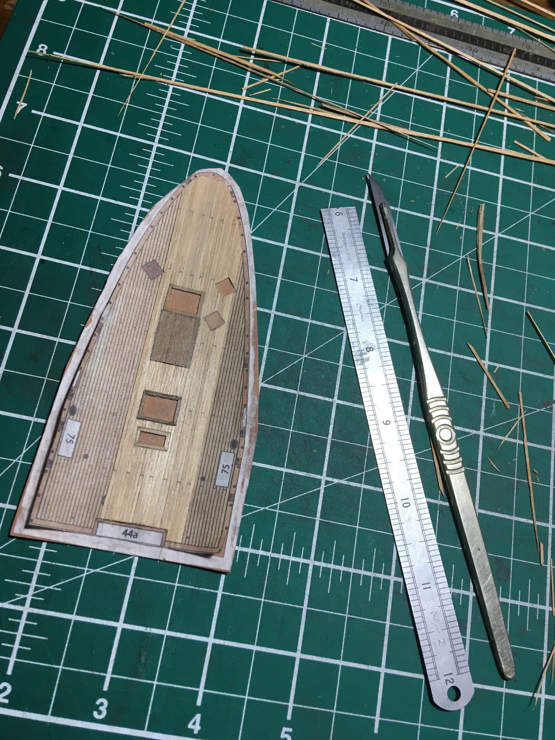
Cutting is a lengthy process and requires an extremely sharp and thin blade and a good straight-edge. As a straight-edge I prefer to use a scraper, as it is sharpened to cut on the edge. Very usefully, the mushroomed edge grips the paper or wood under it, which is ideal to stop creep while you are cutting. If you don’t have one or know how to sharpen it, any carpenter or furniture-maker will lend a hand, I’m sure. Any metal ruler will do, of course, too.

As a blade, use a safety-razor-blade, an old cut-throat razor (my favourite), a scalpel or a ‘Stanley’-knife, whichever is more comfortable. I actually use all of those, depending on the job, though for the decks, both the razors are more accurate for the strips, cutting a proper 90 degrees as the blade is so thin and doesn’t ‘cut and wedge’ like the thicker scalpel and Stanley tend to do, leaving the cut edges in a ‘v’ shape. Any tendency to wedge can be nasty when combined with a slightly angled grain, too, pulling the knife along it. A thin blade is paramount when ‘correcting’ the width of the planks, since realy minute amounts are shaved off to get them ‘just right’. What you cannot see, is that I actually sand the edges of some of the planks to get them at right angles and to be the right width 🙂

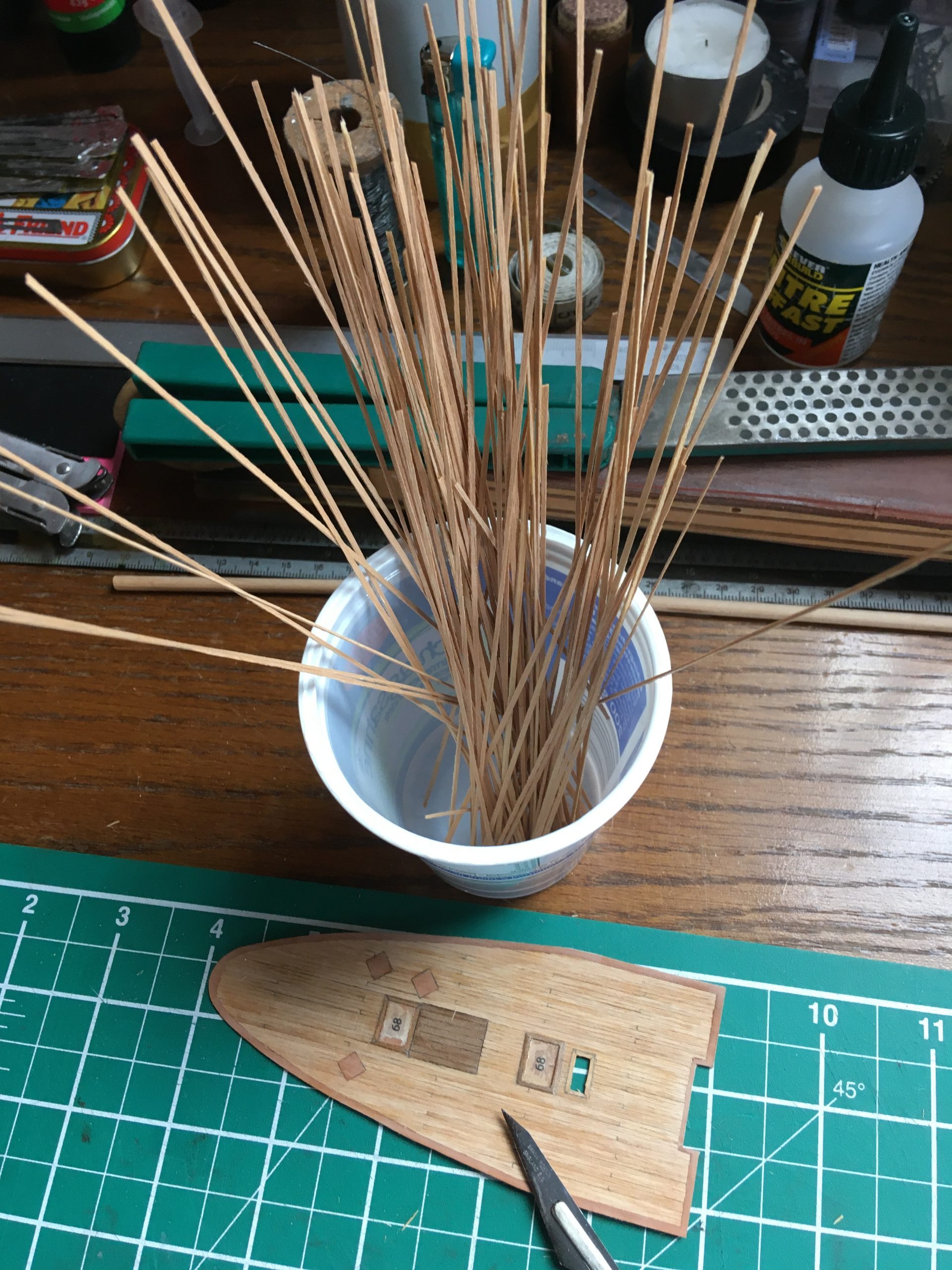
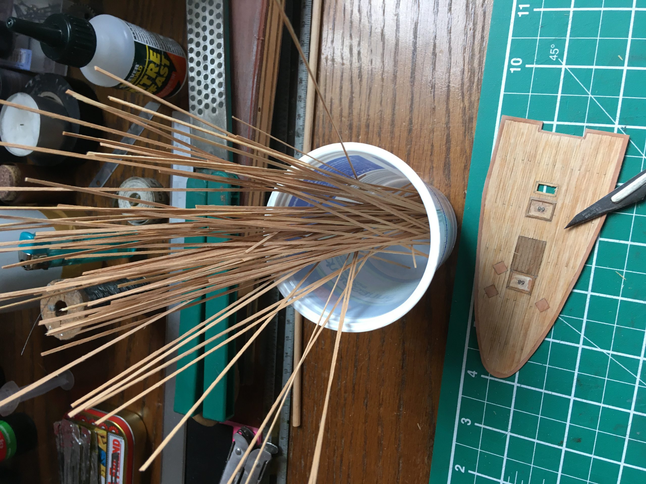
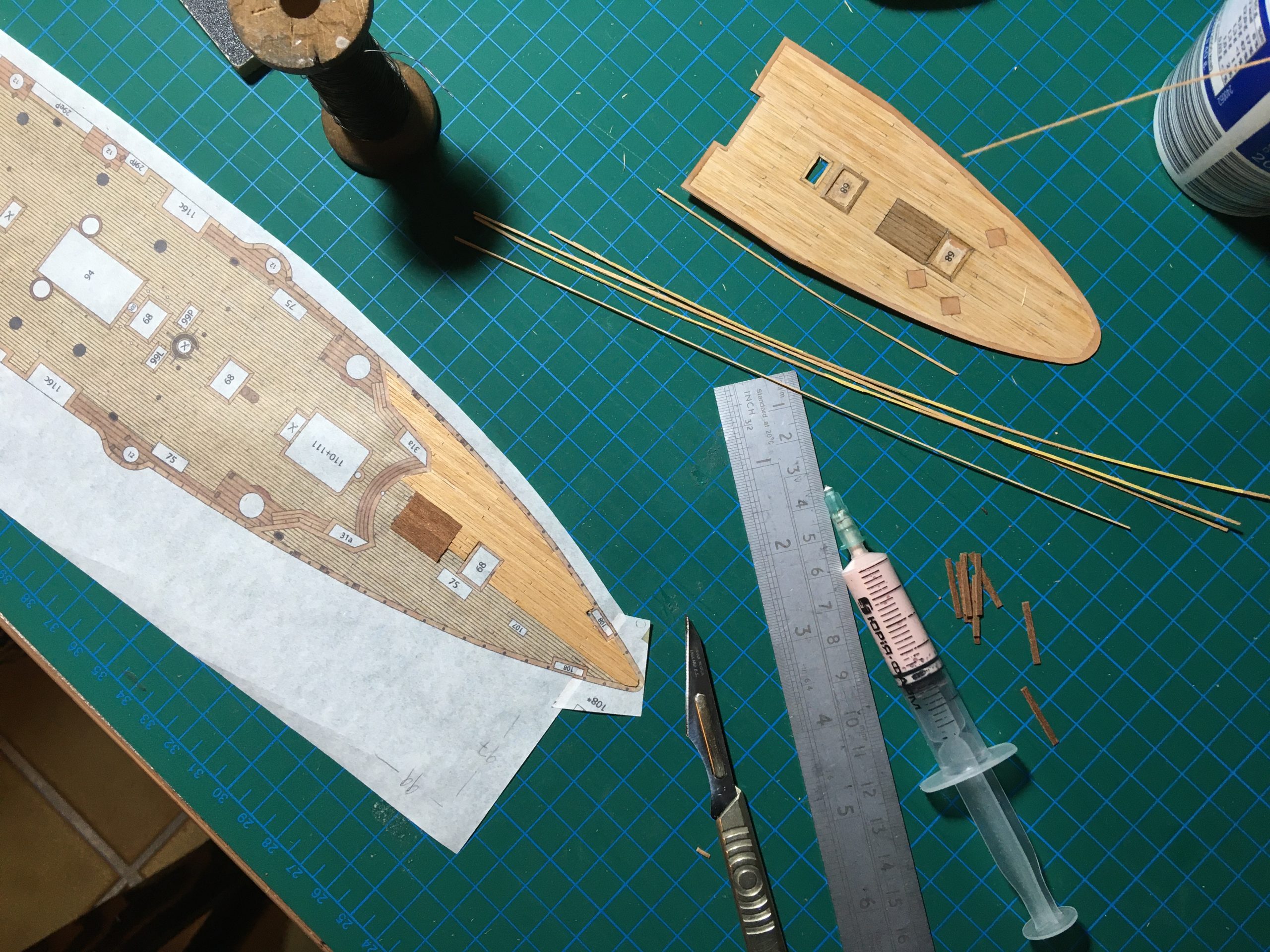
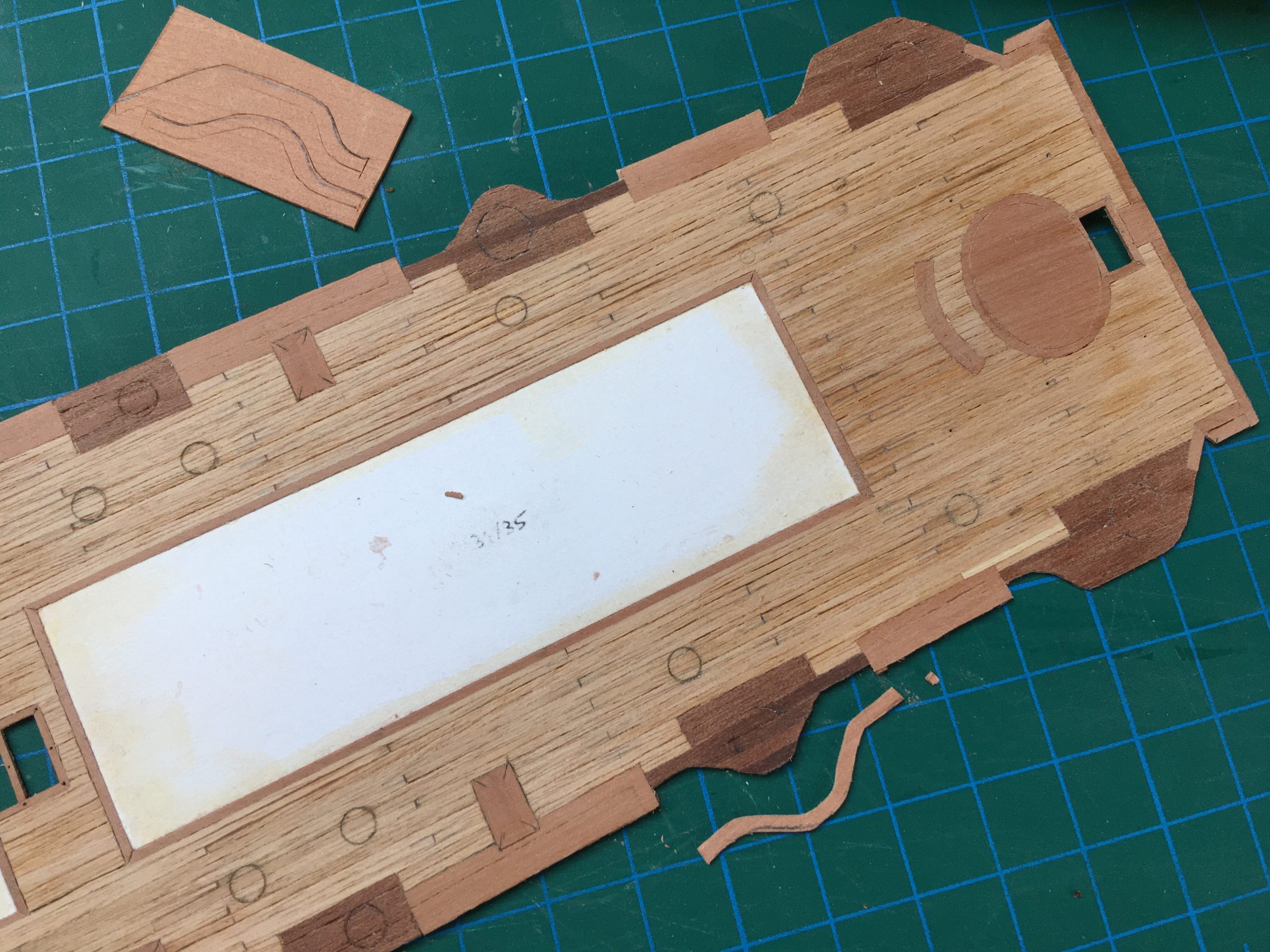
The forward deck is planked and there are some more planks ready for the aft portion of the deck, which comes next. Here are a few pics at the beginning of the planking process and the started work.

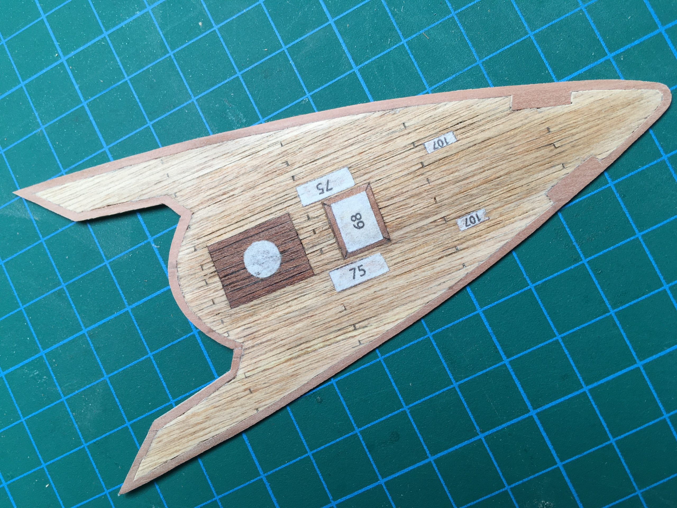
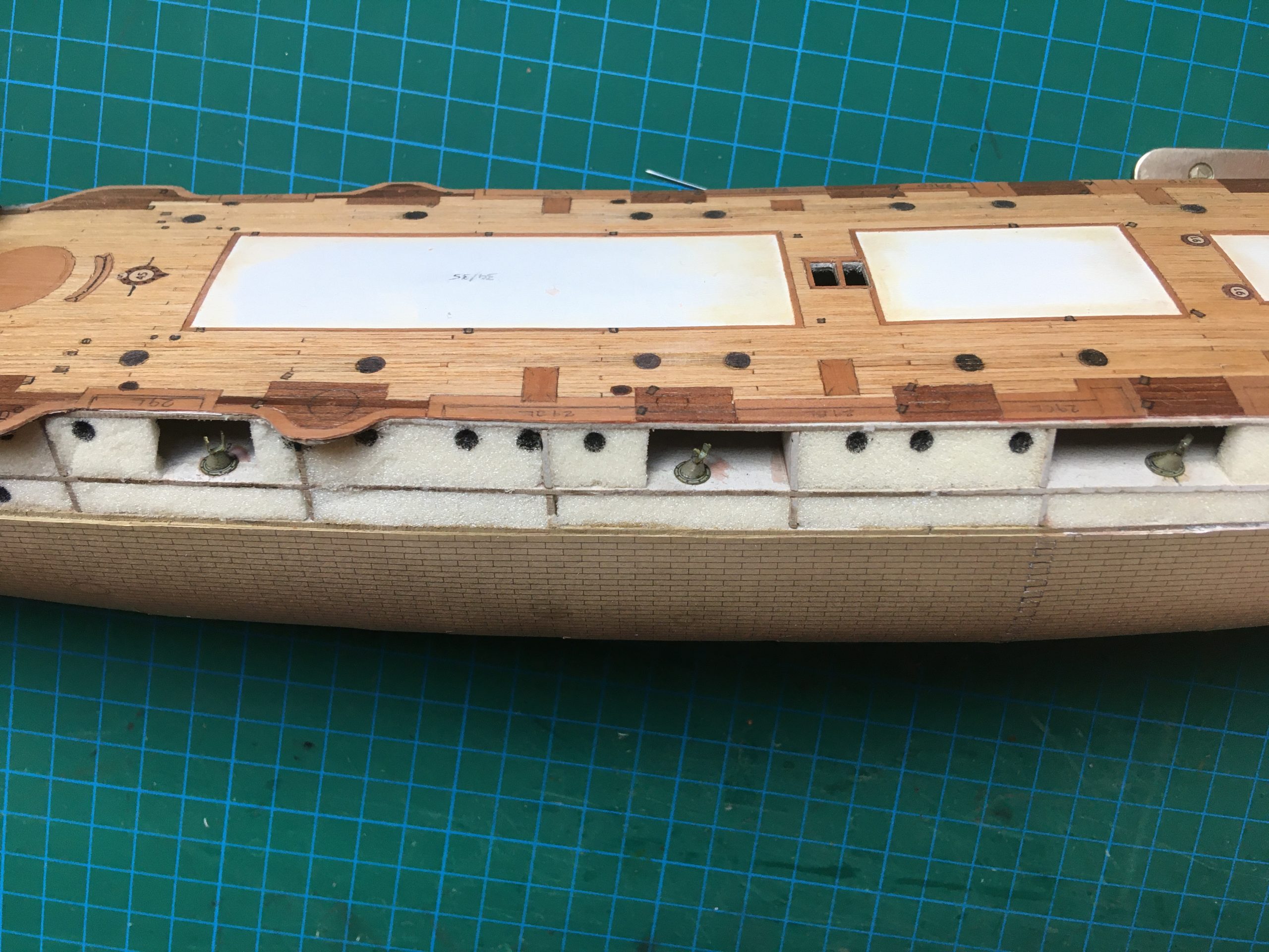
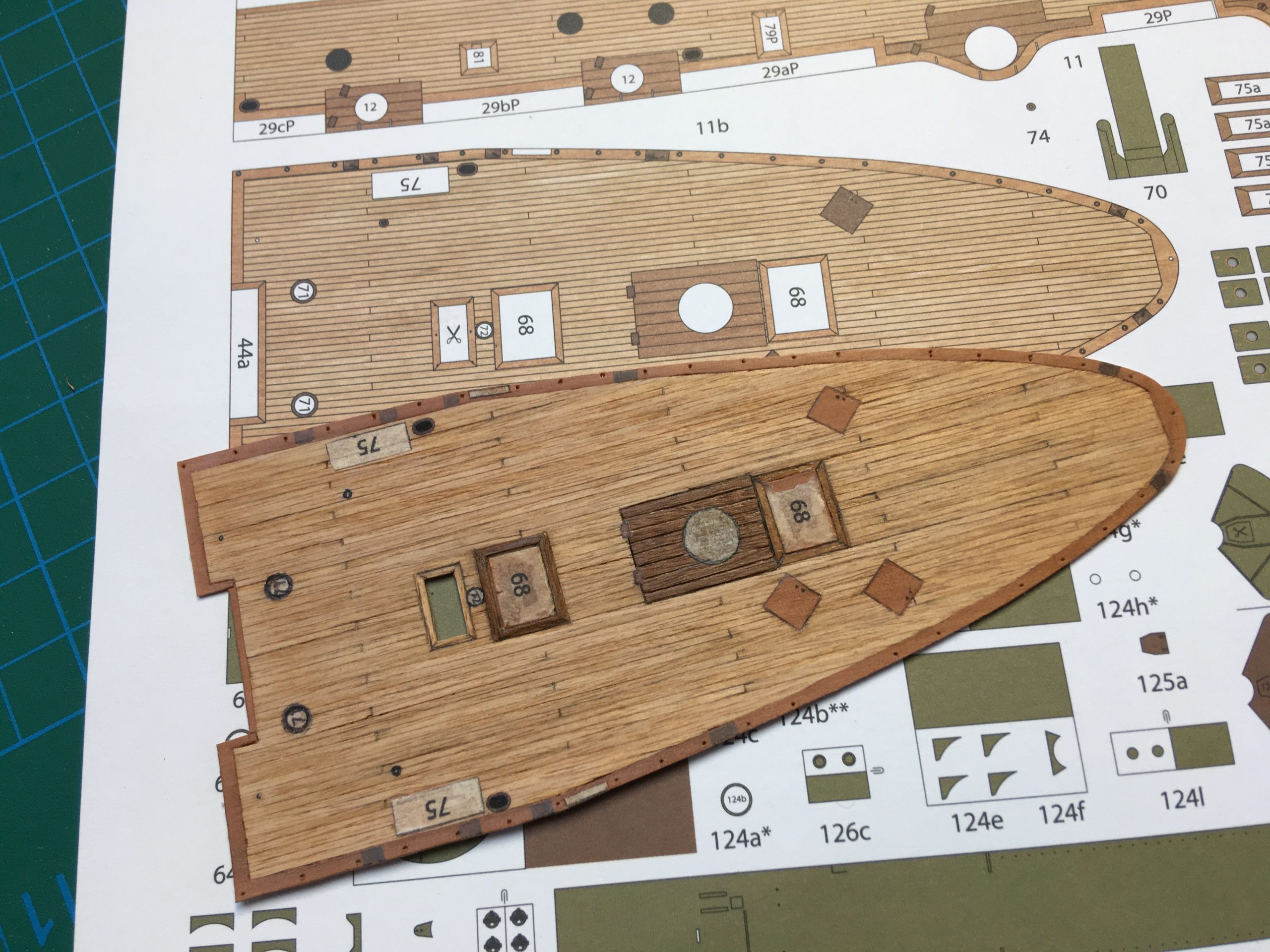
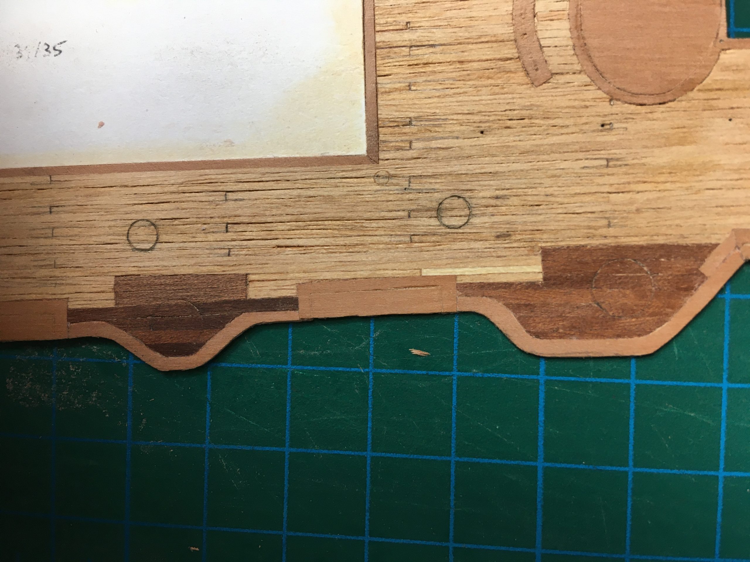
Here we see the finished aft deck planked in various woods placed over the original printed sheet from the model. A nice weathered look achieved with Schellack and elbow-grease. Hopefully not over the top when it’s finished. The individual planks are never cut from the same strip when they are laid, I always mix them up, otherwise I could take any piece of veneer and draw the plank lines on it. My rather more complicated method gives a little more of an ‘authentic’ look and feel to it, I hope.

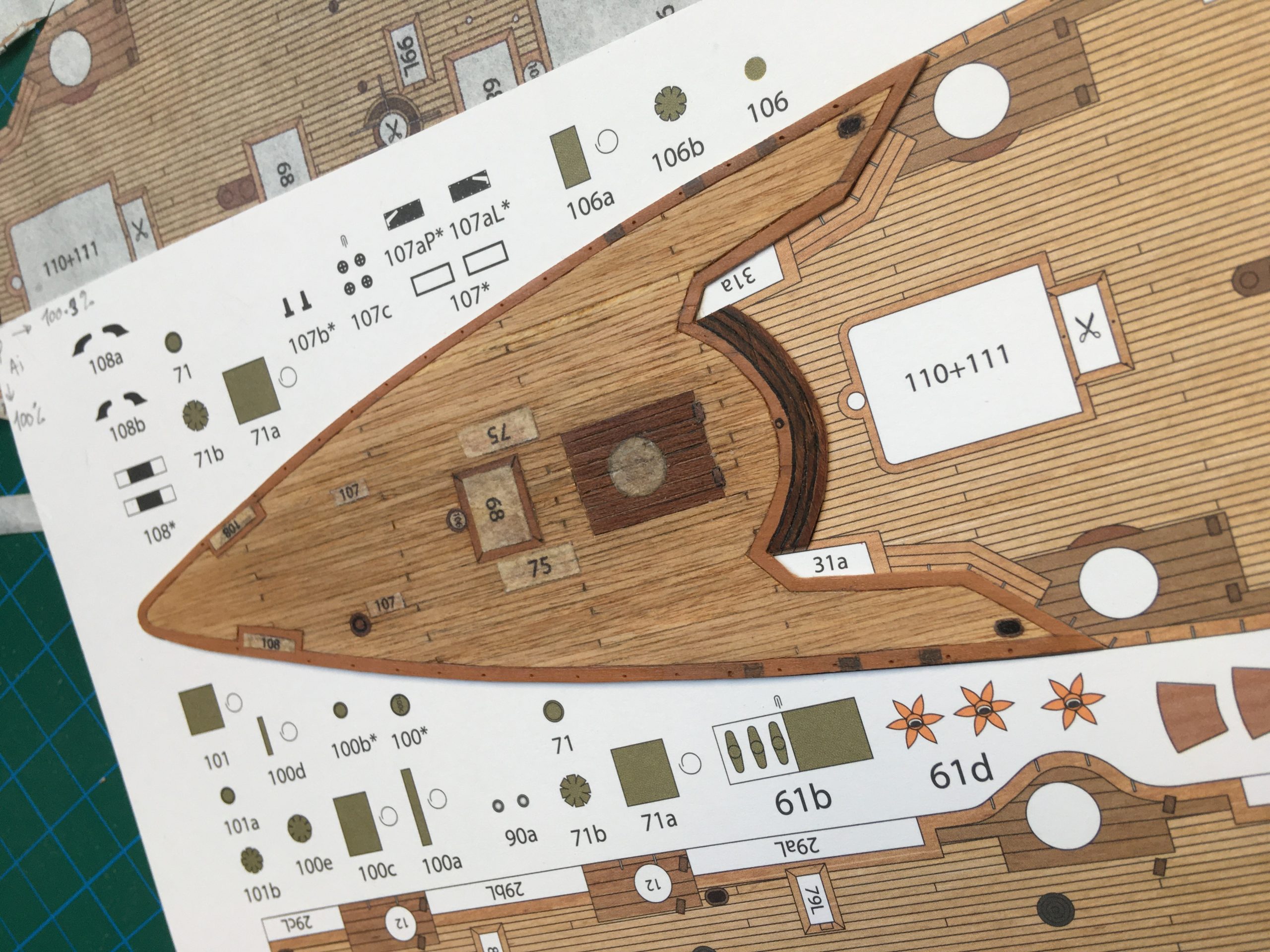
And here the fore-deck in the same manner.

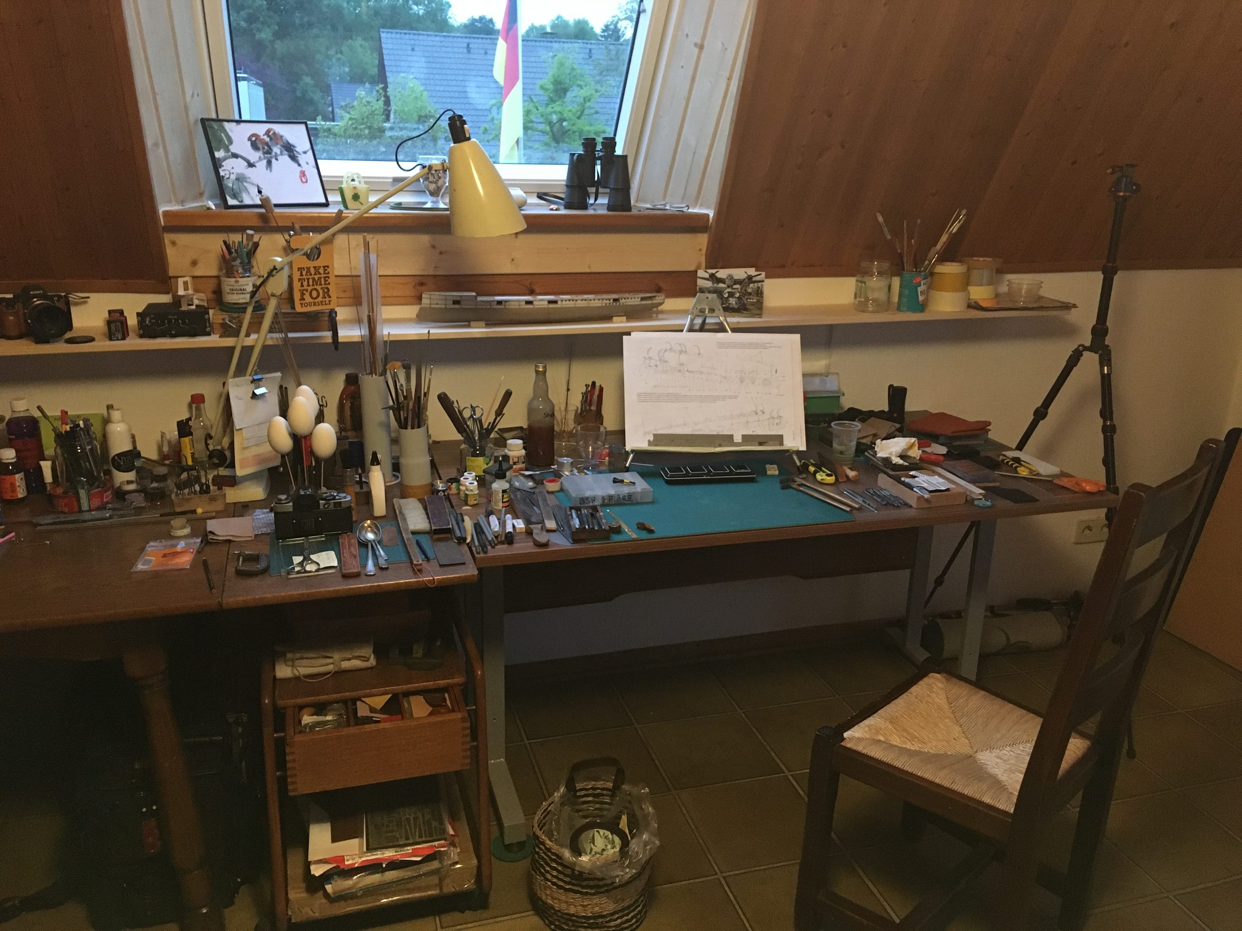
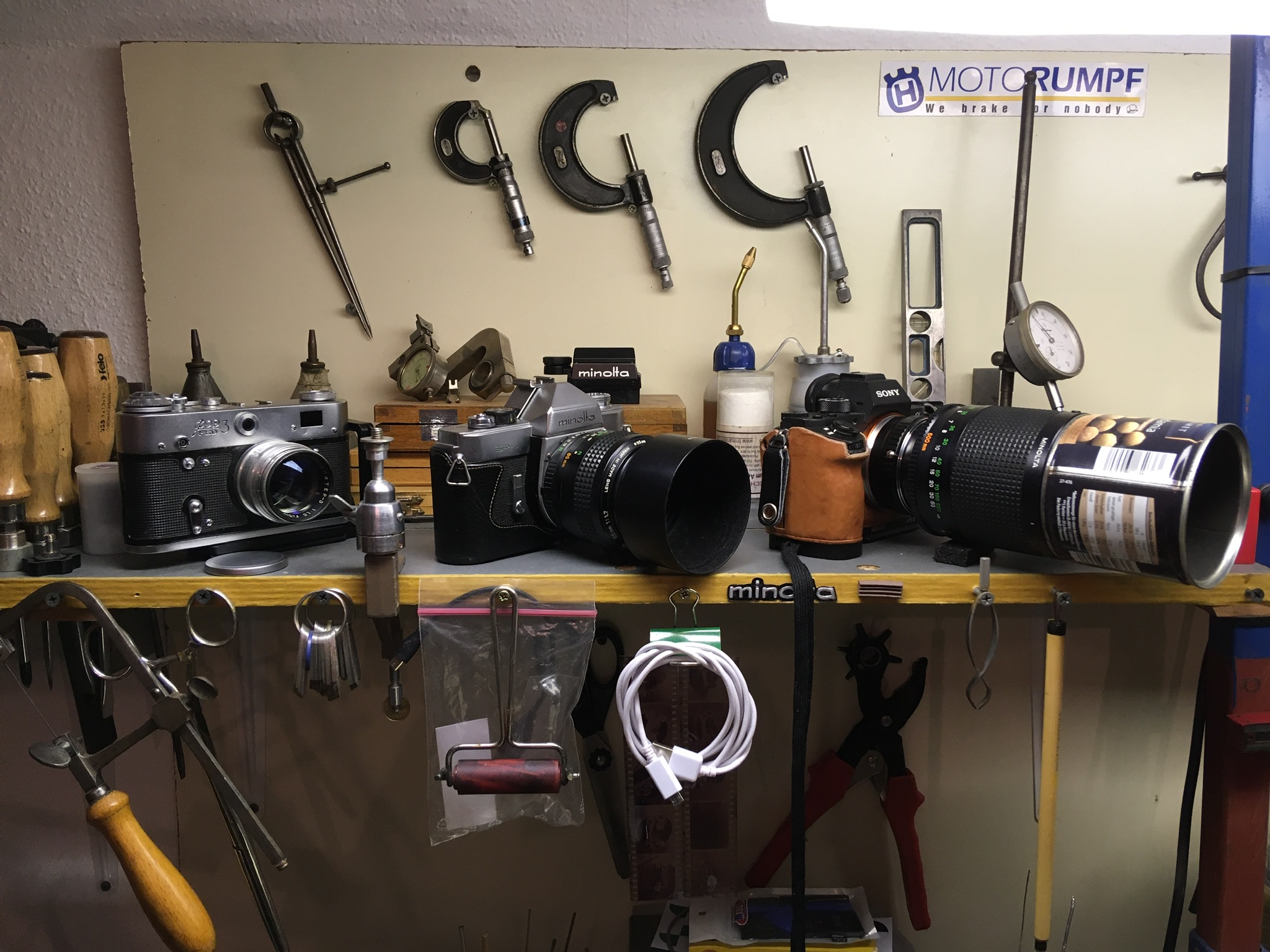
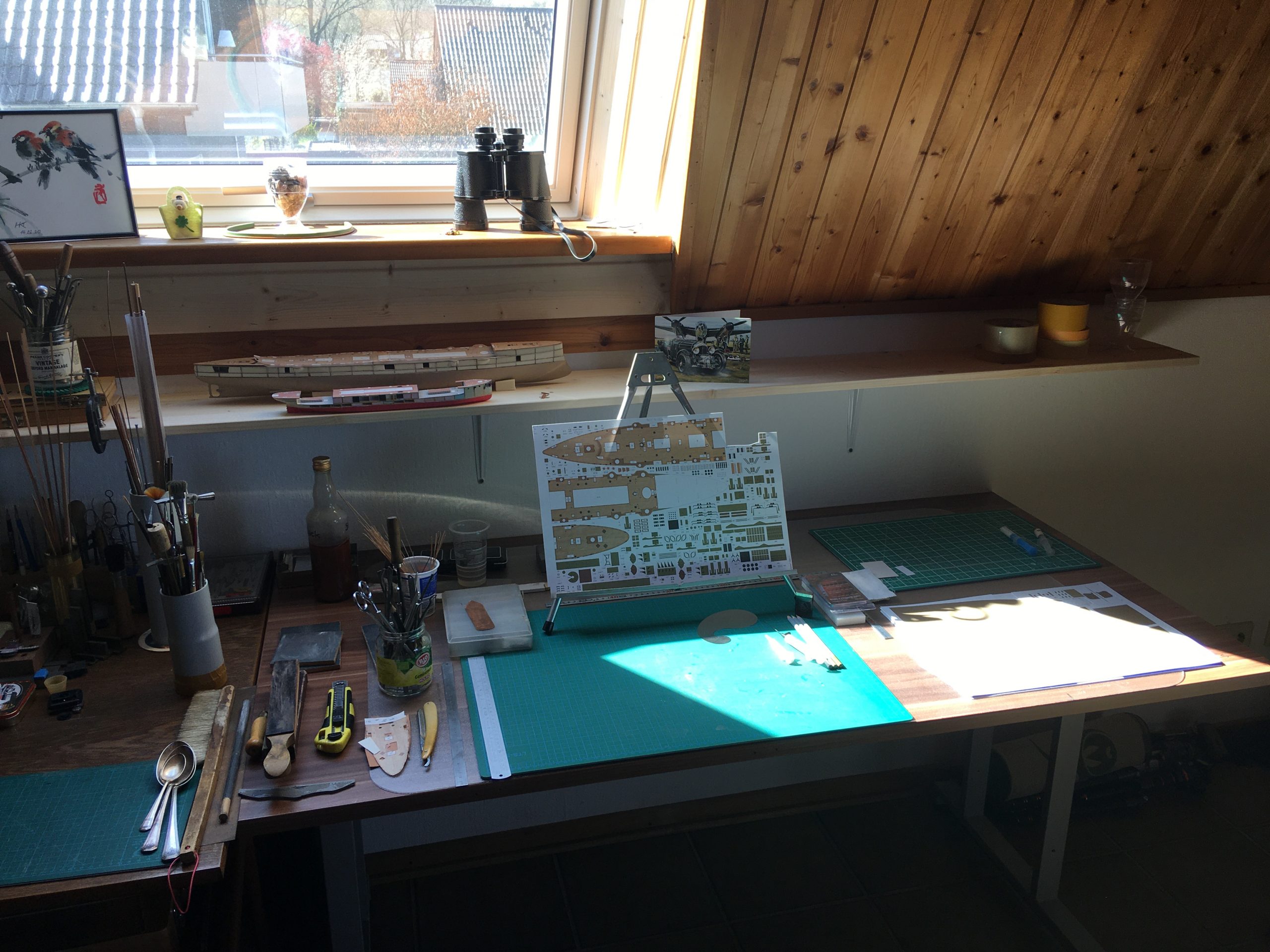
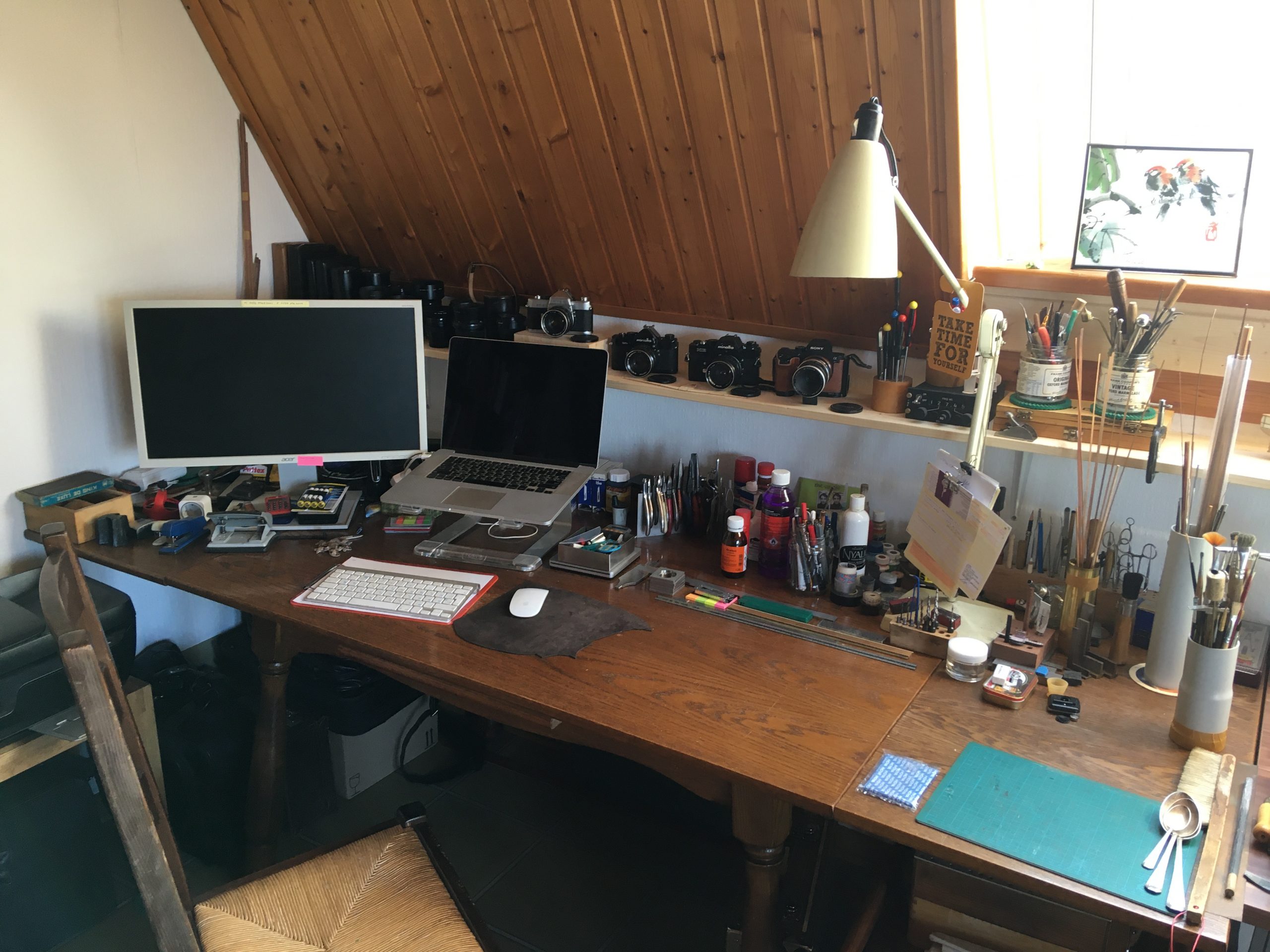
You may even spot the array of tools and useful bits and pieces in the background now and then. Here is a view of my workspace in the ‘living-room’, where Maryna does her art (mostly painting) and I do my various tinkering. Looks nice and tidy here, doesn’t it!

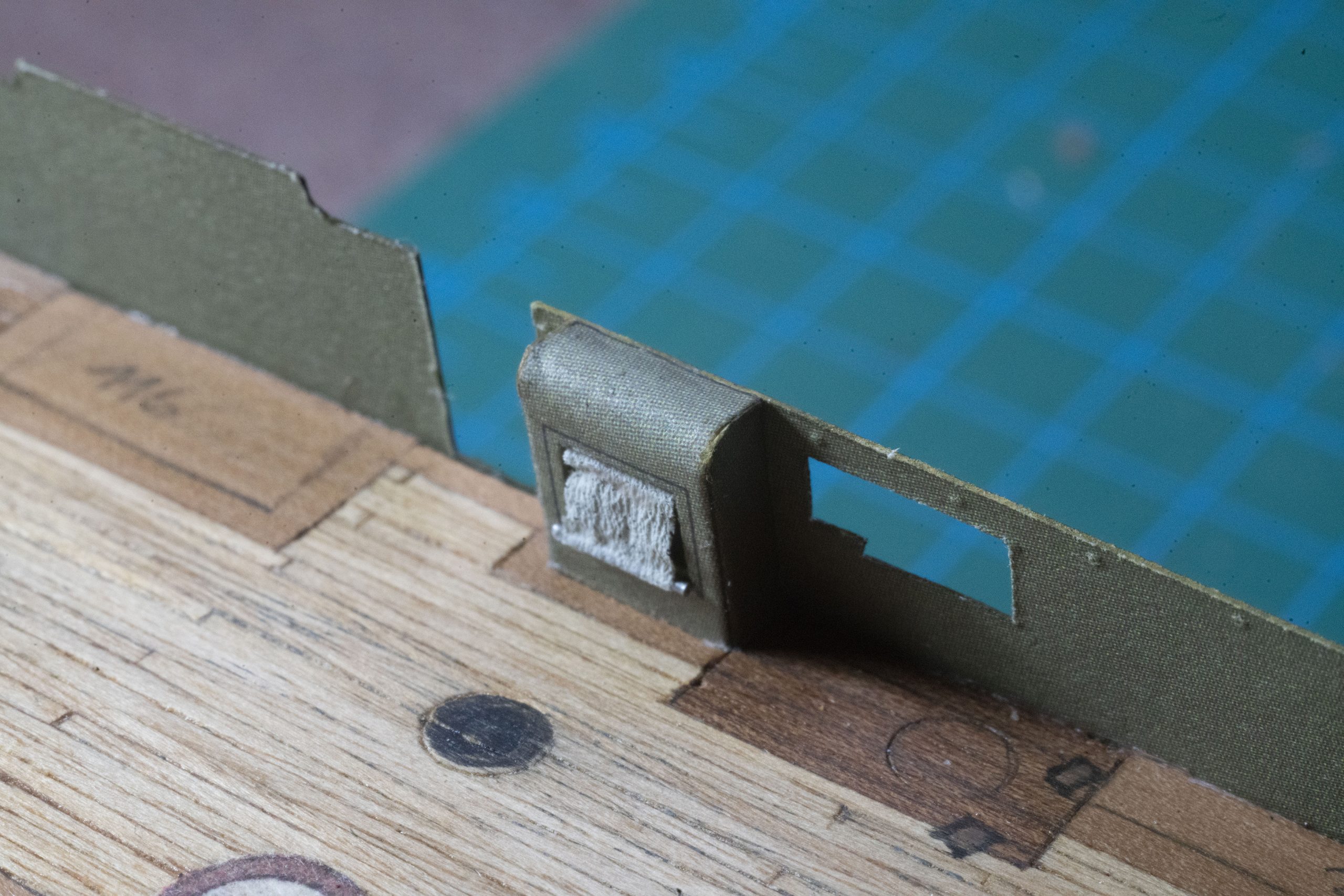
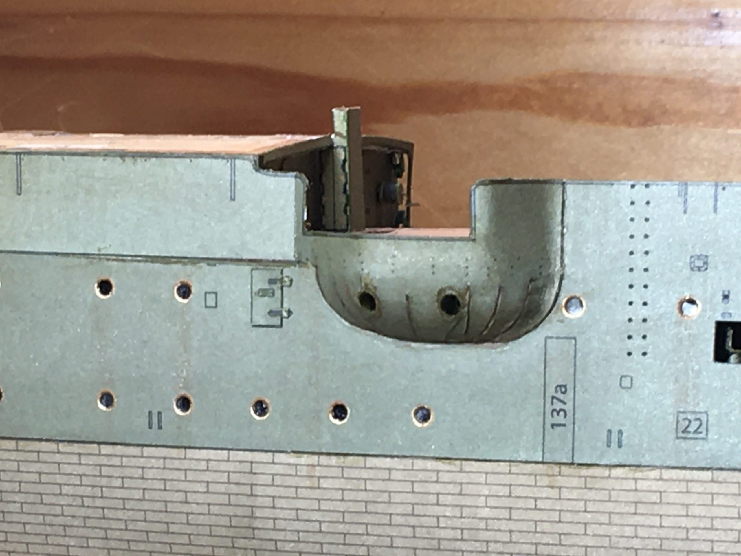
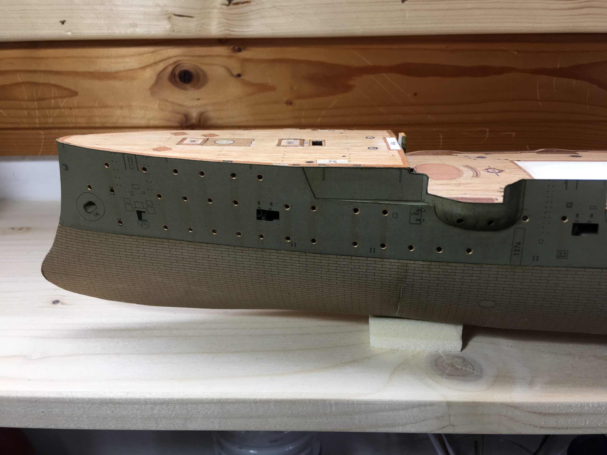
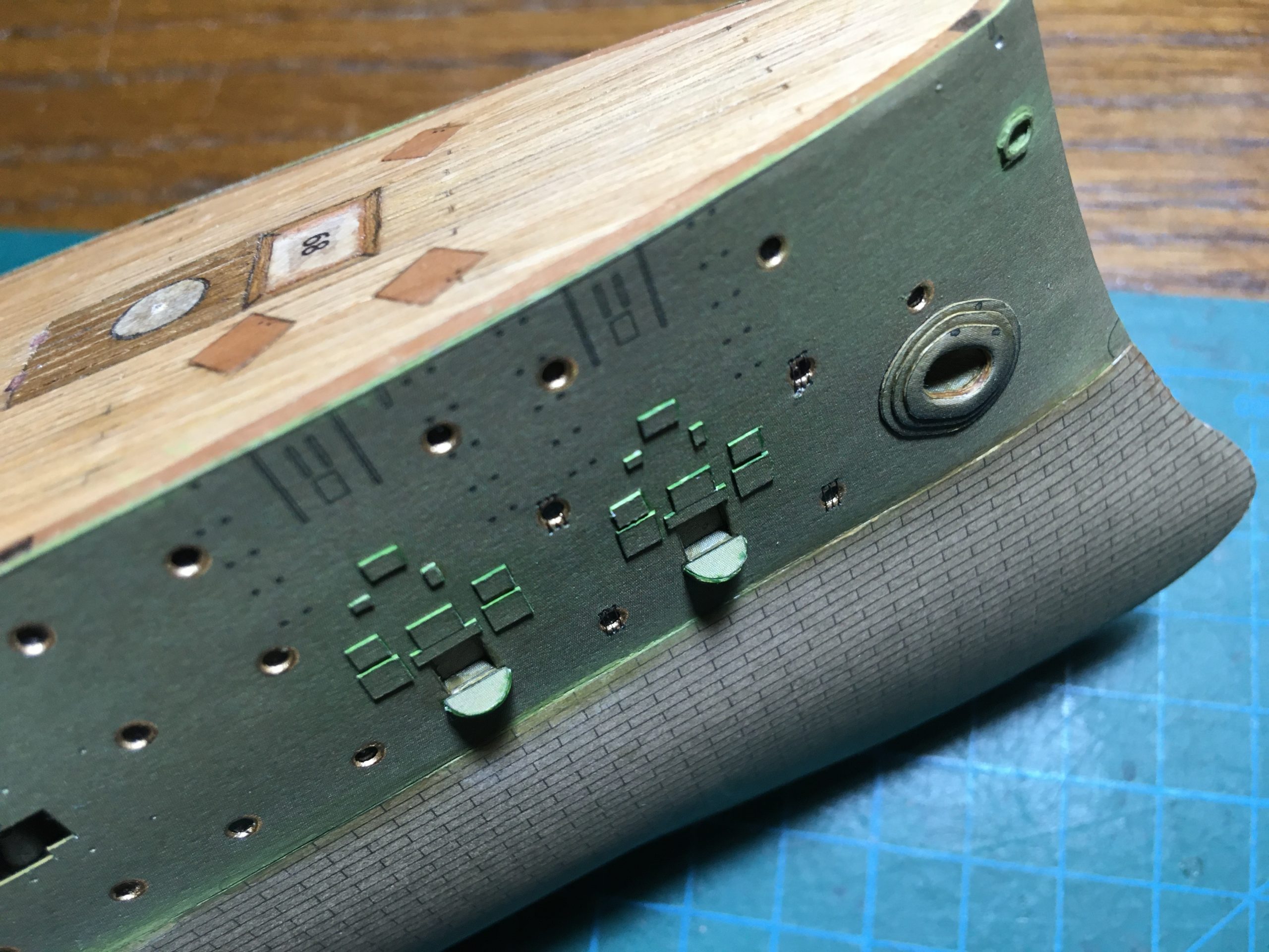
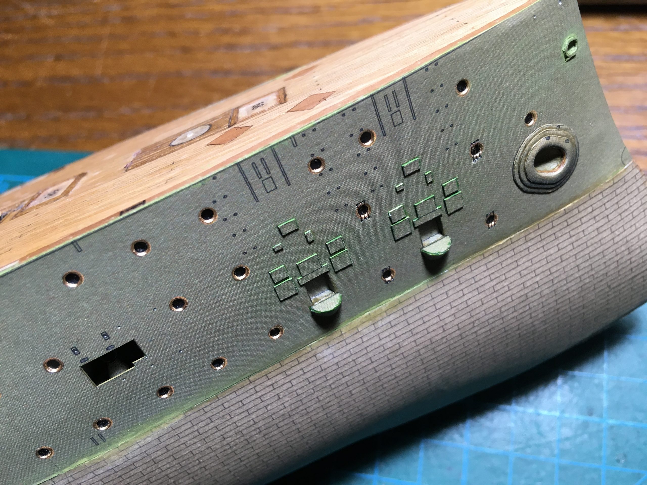
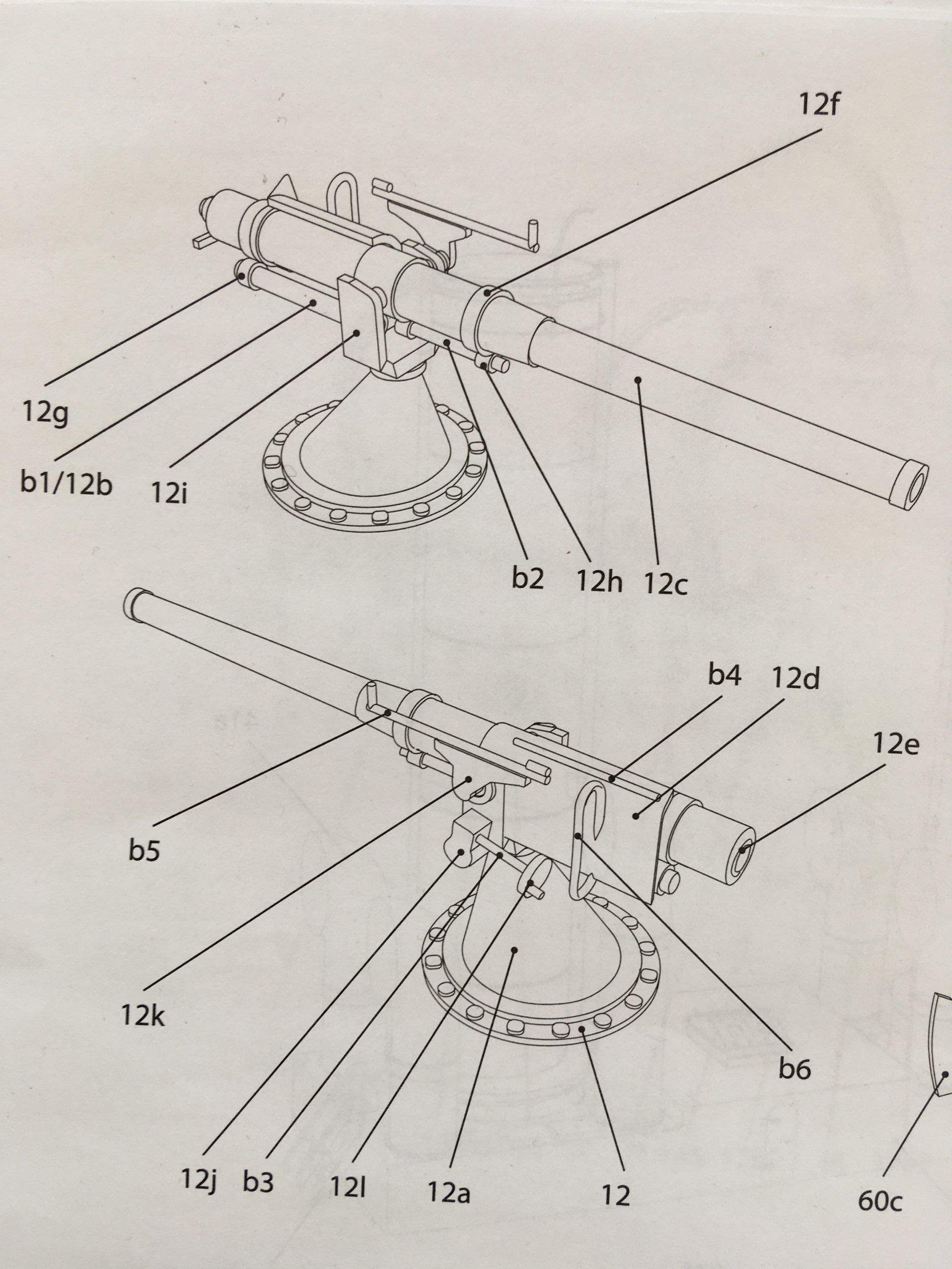
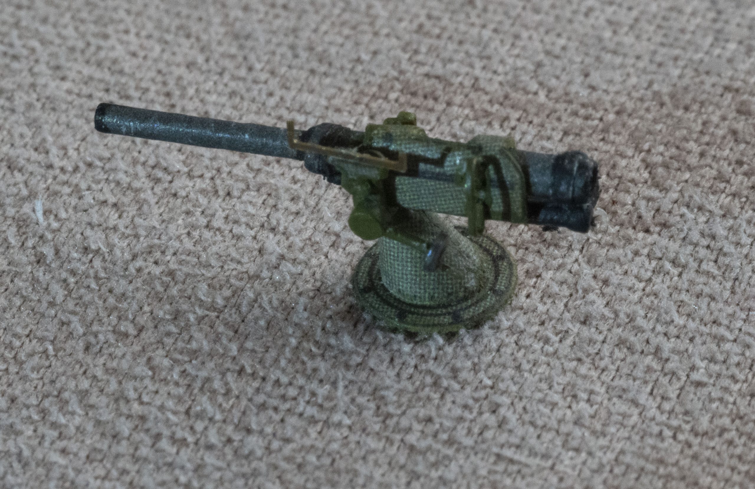
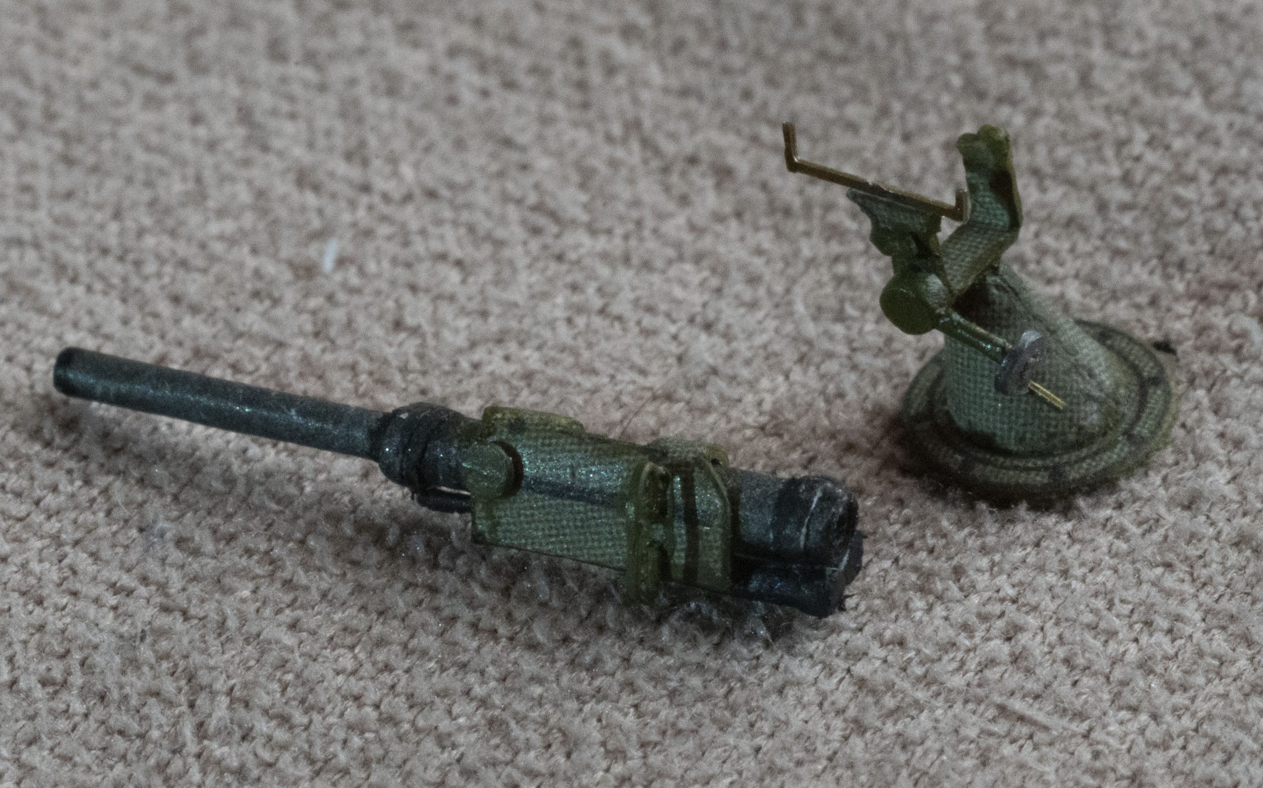
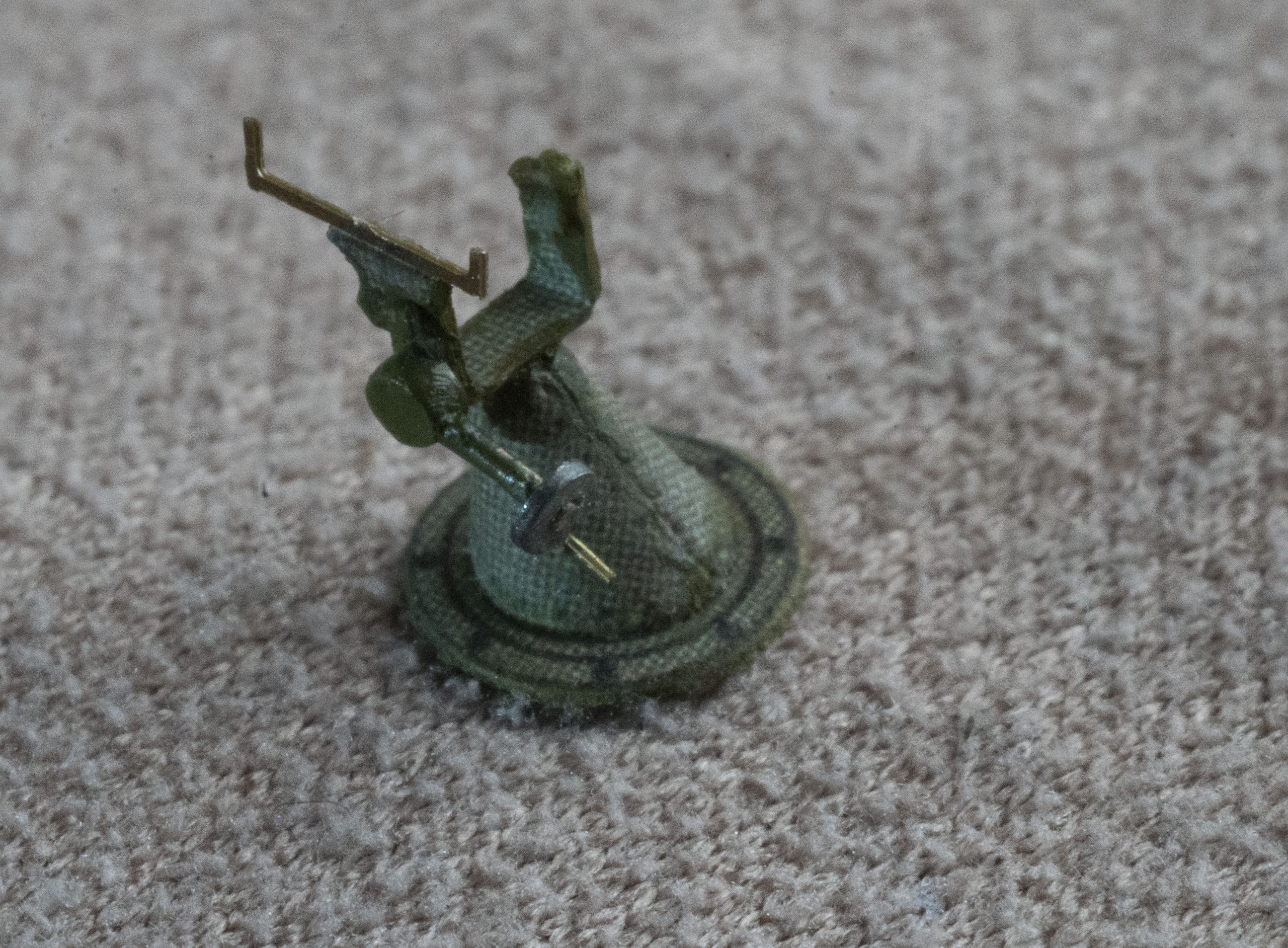
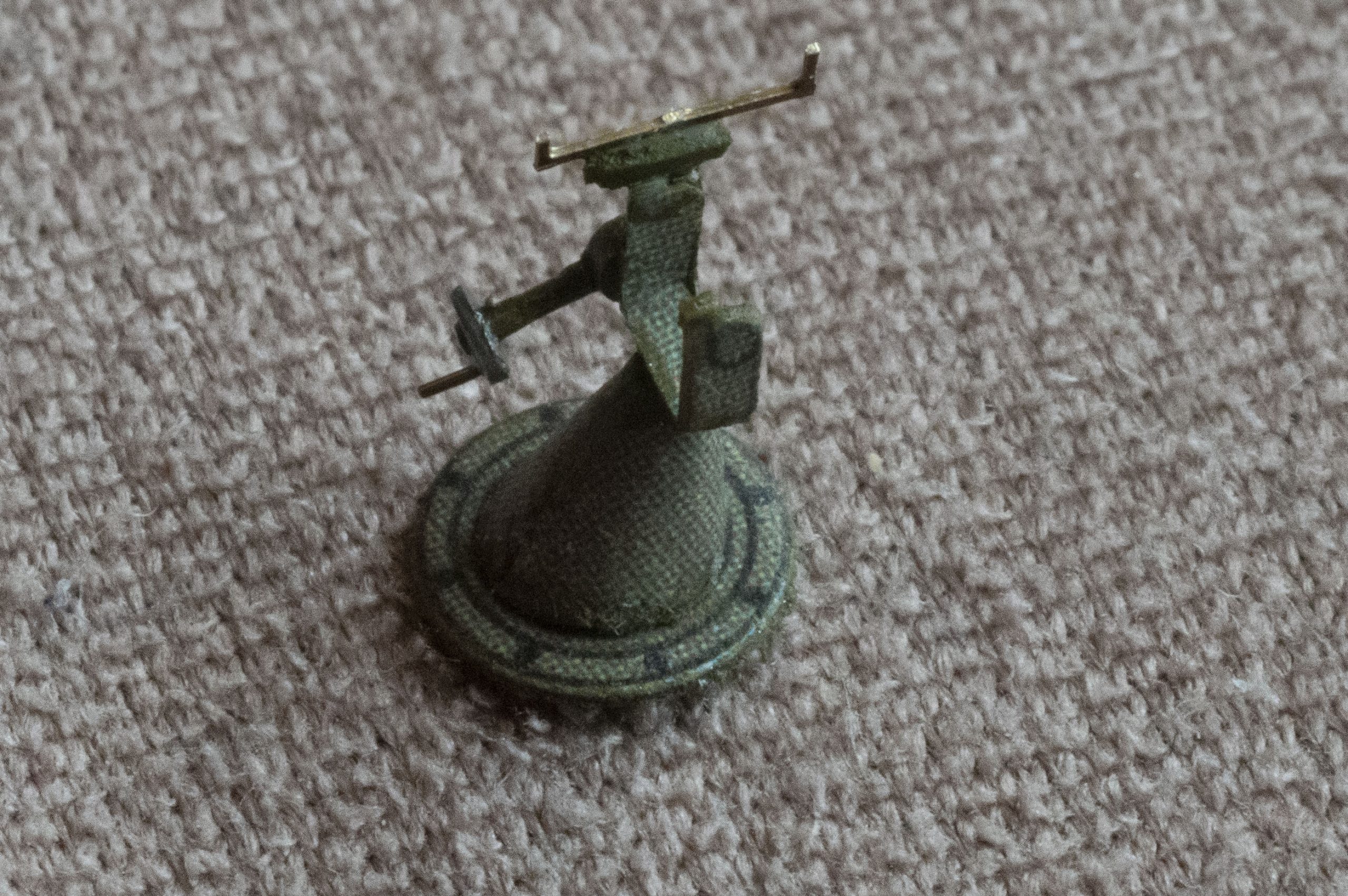
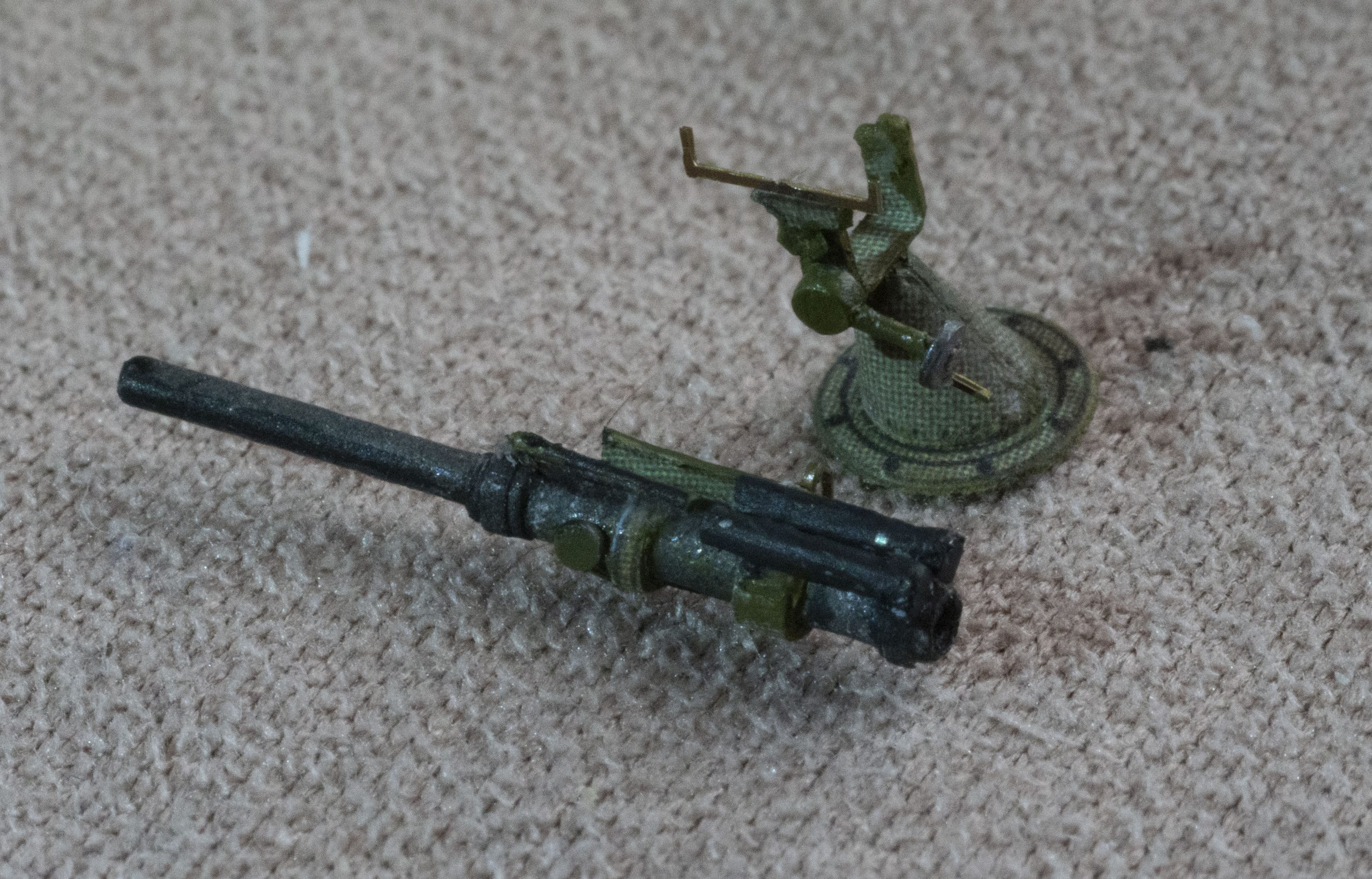
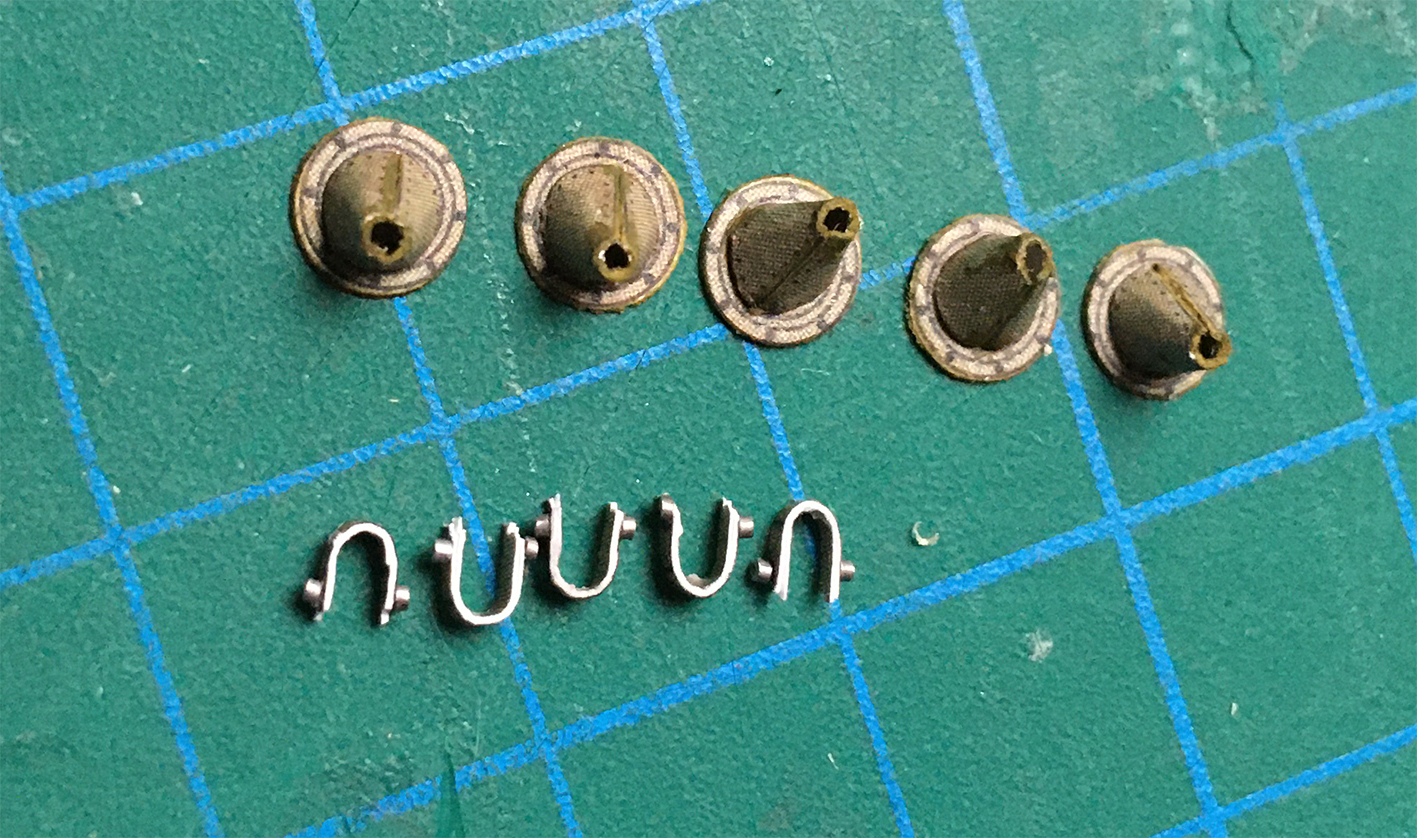
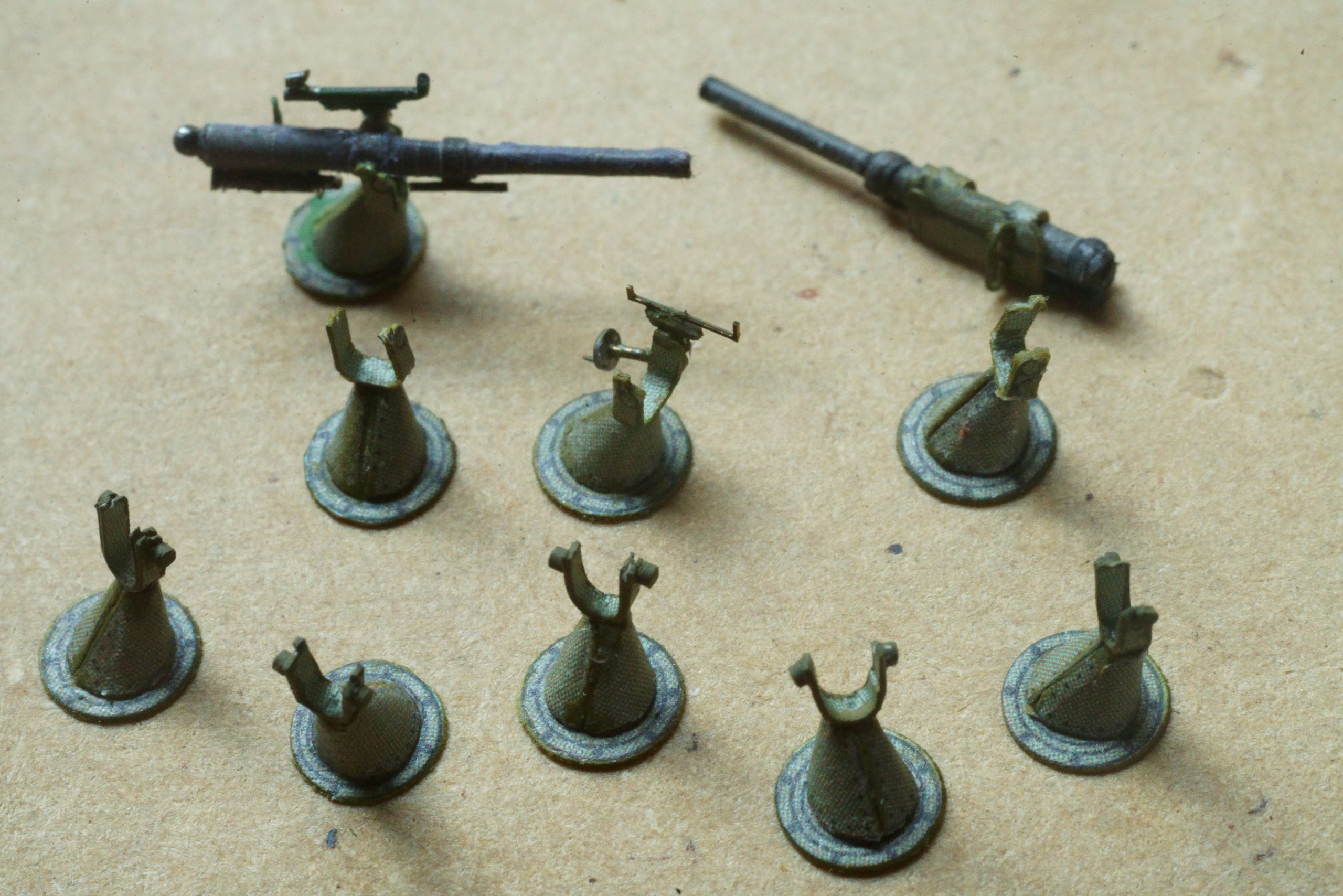
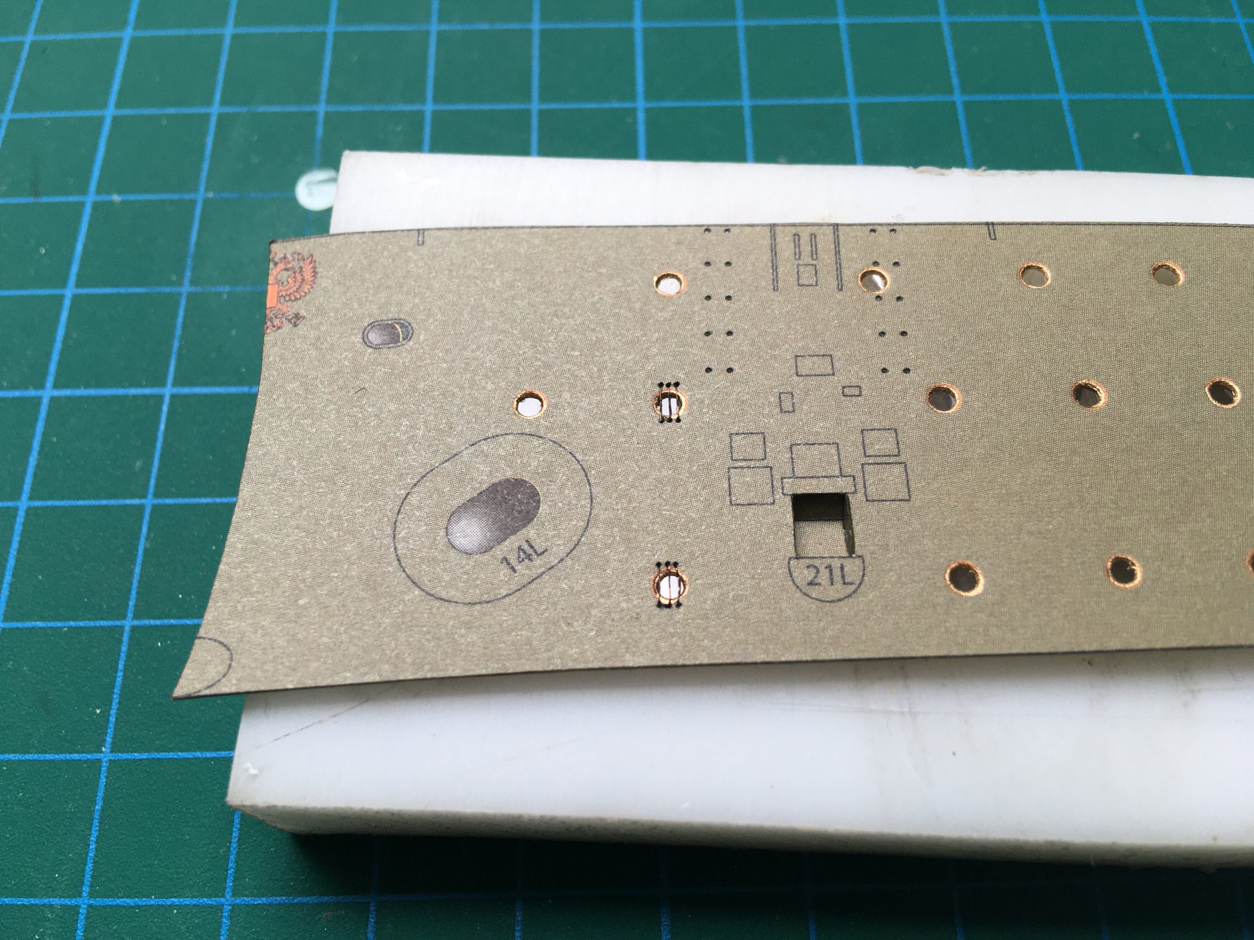
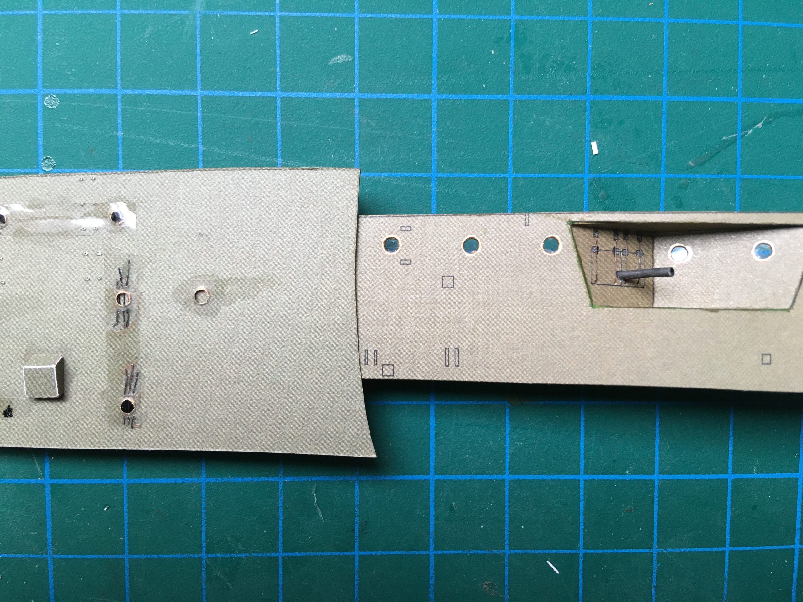
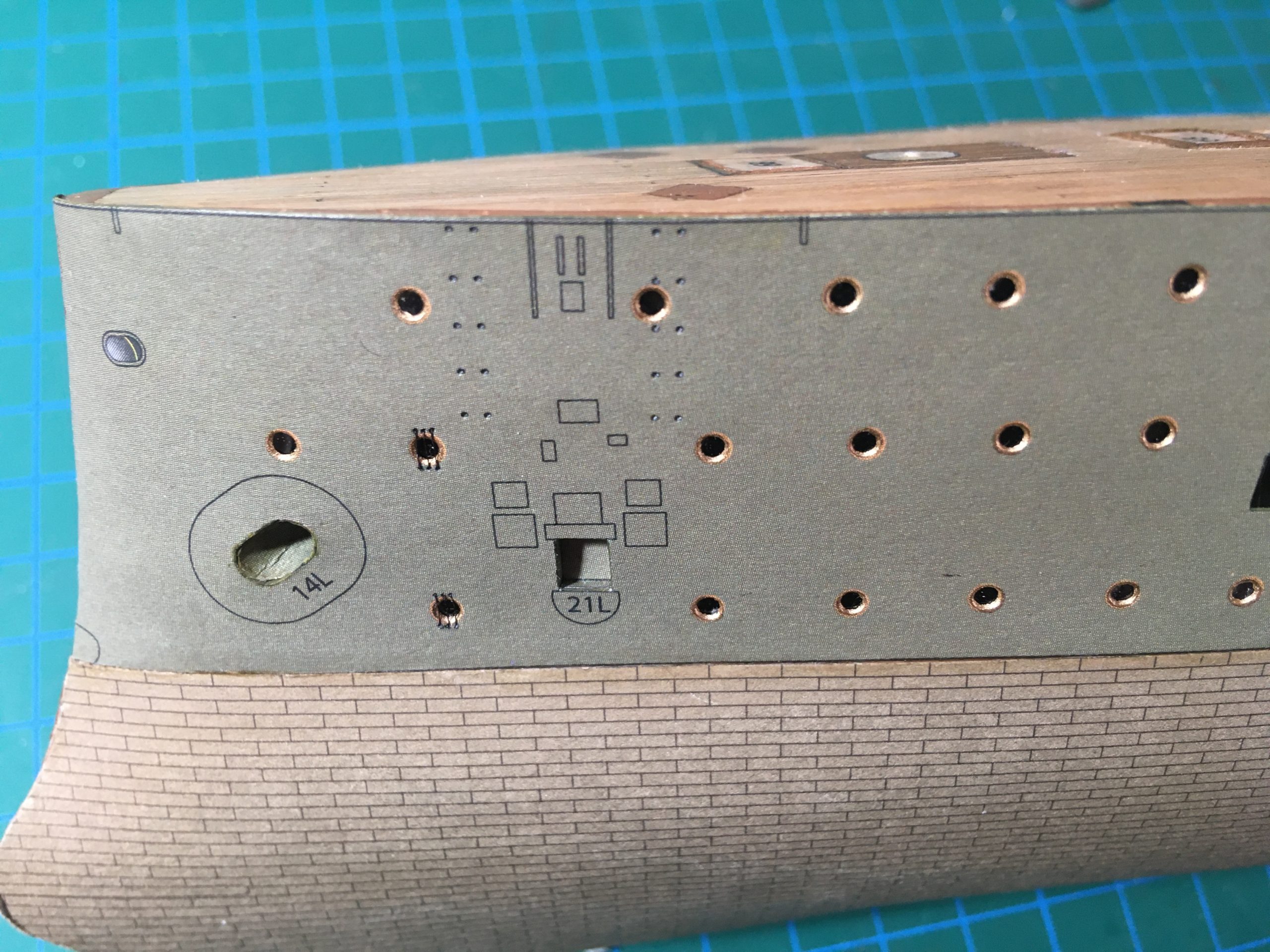
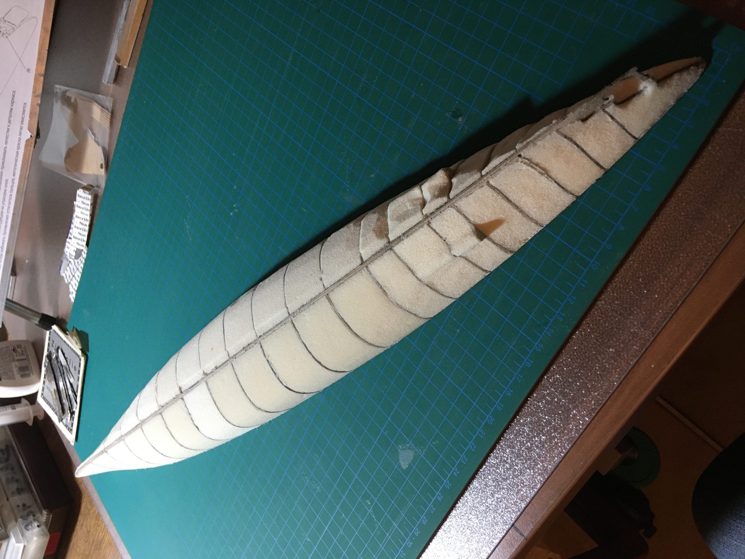
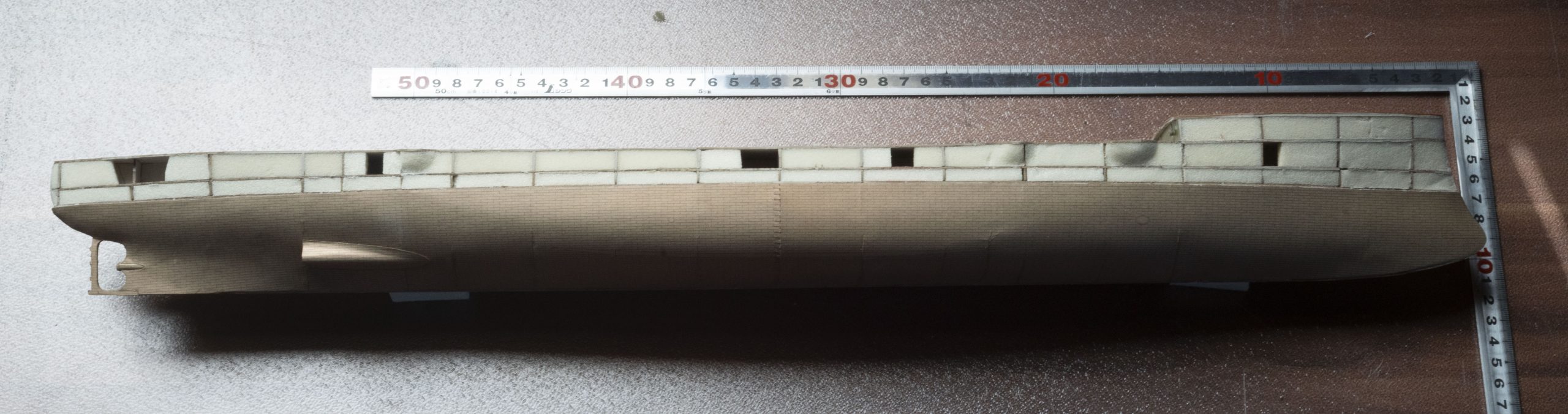
While the deck was drying, in between I finished most of the hull below the waterline, as shown earlier. Before I can even think of attaching the hull-section above the waterline, the below-decks 75mm Canet guns have to be made and installed in the hull and the deck has to be completely finished.

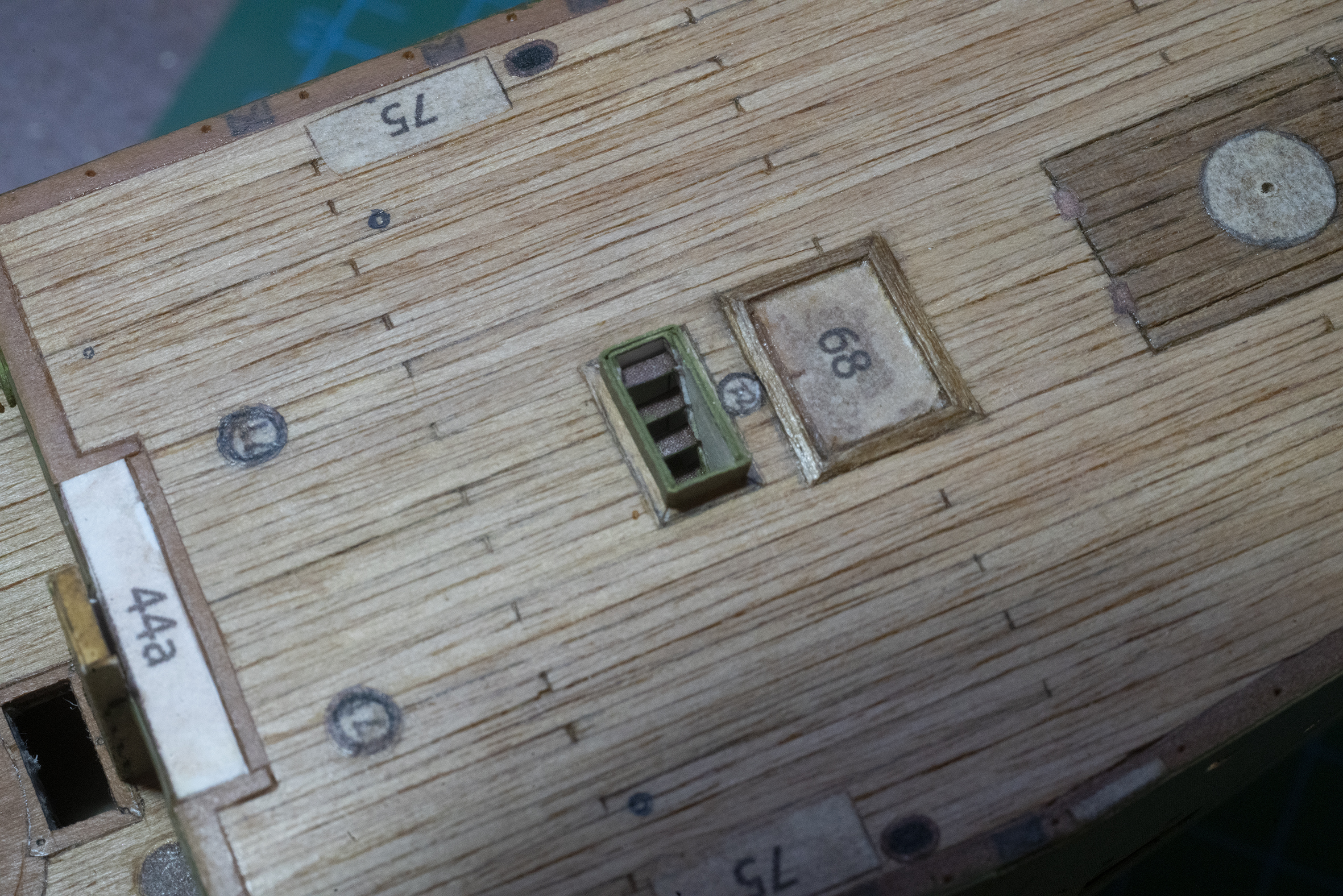
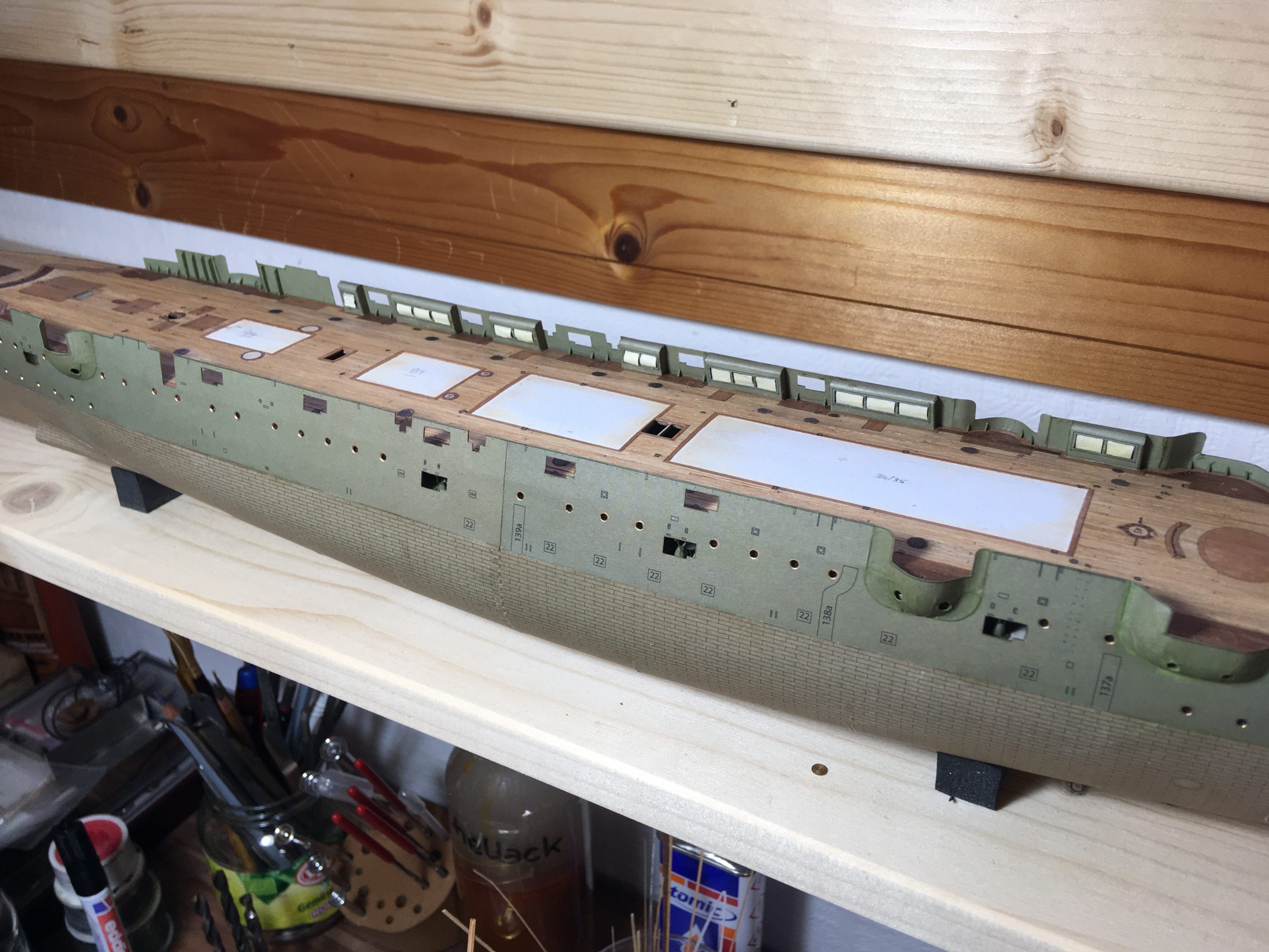
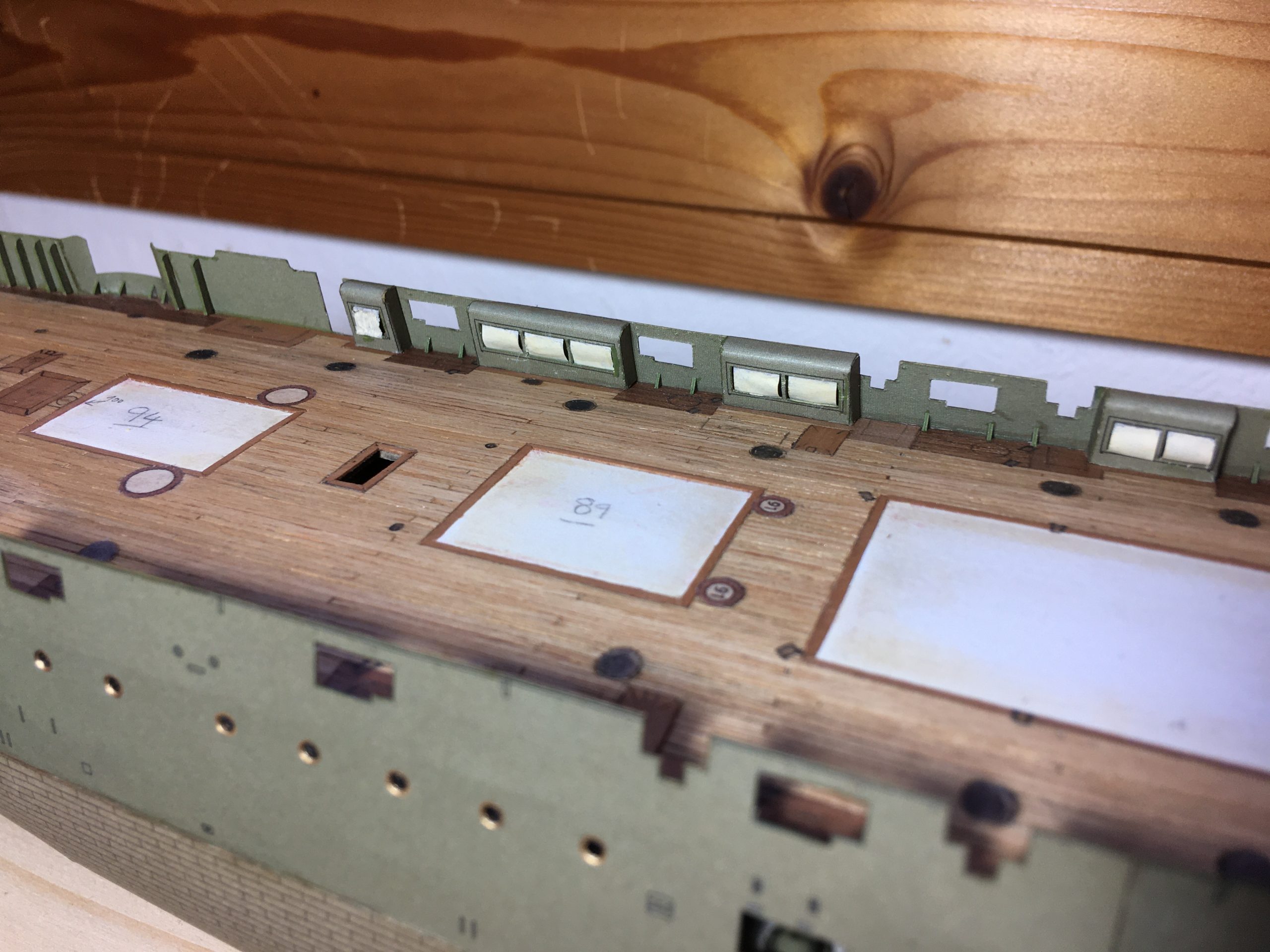
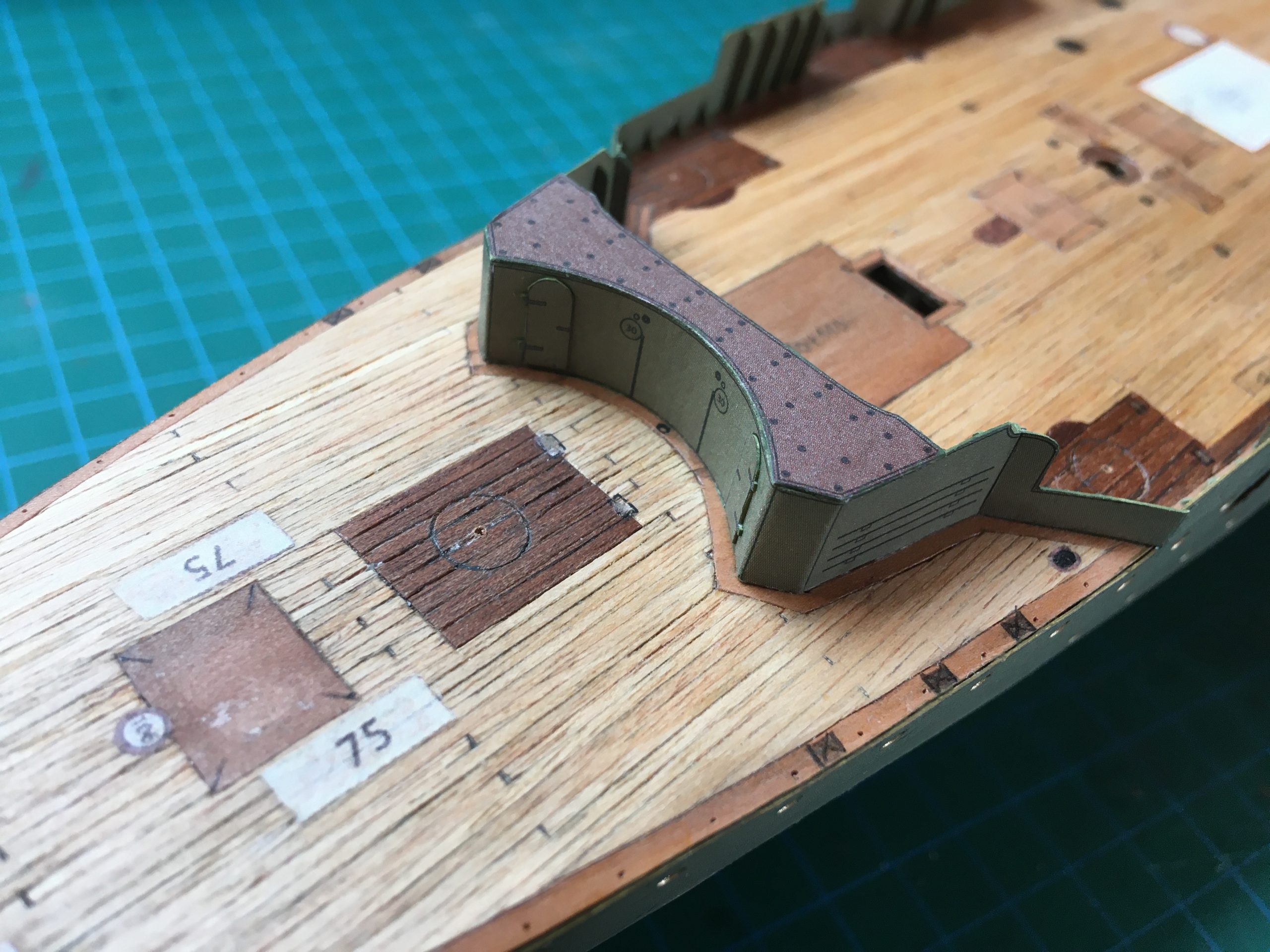
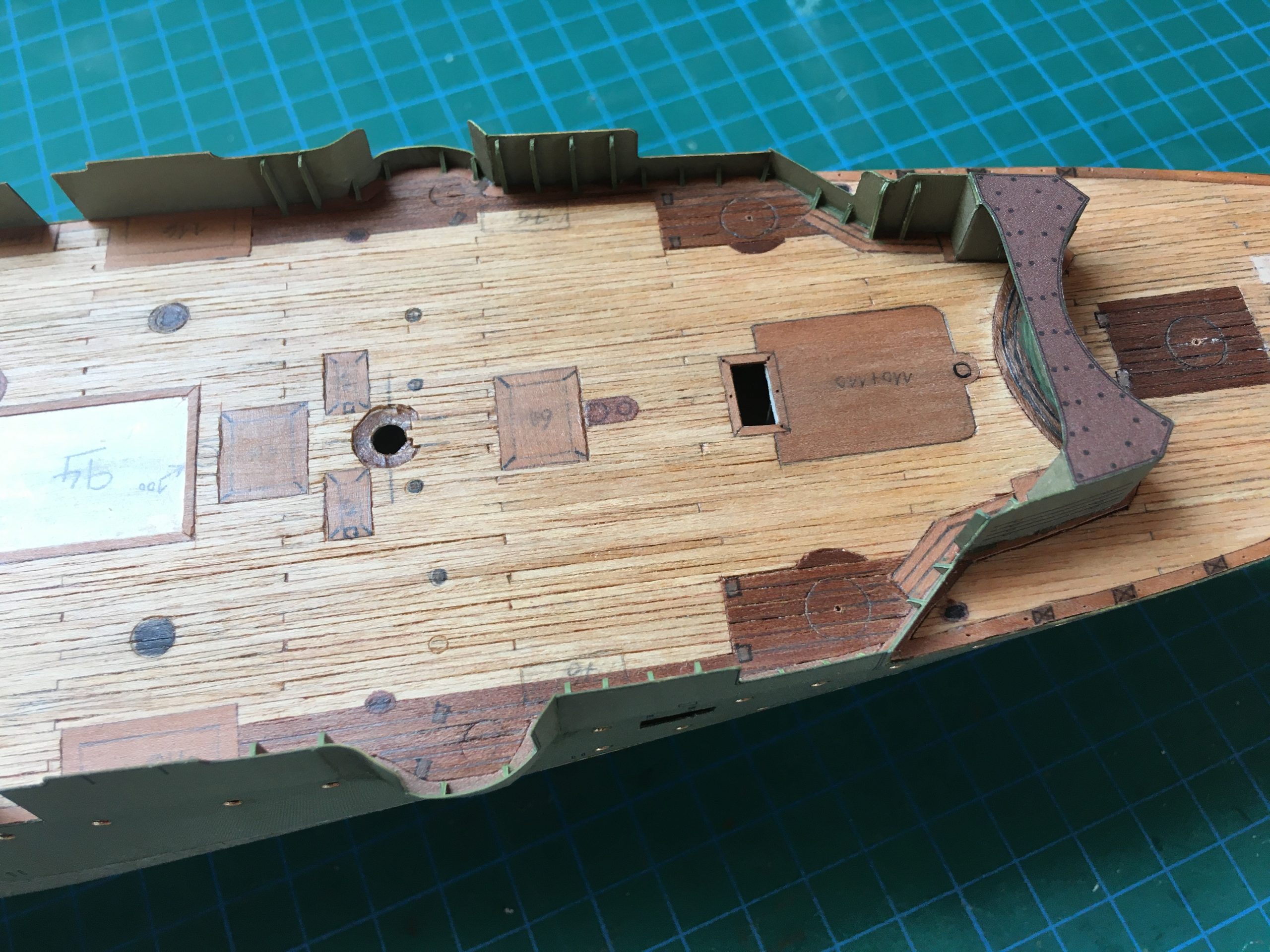
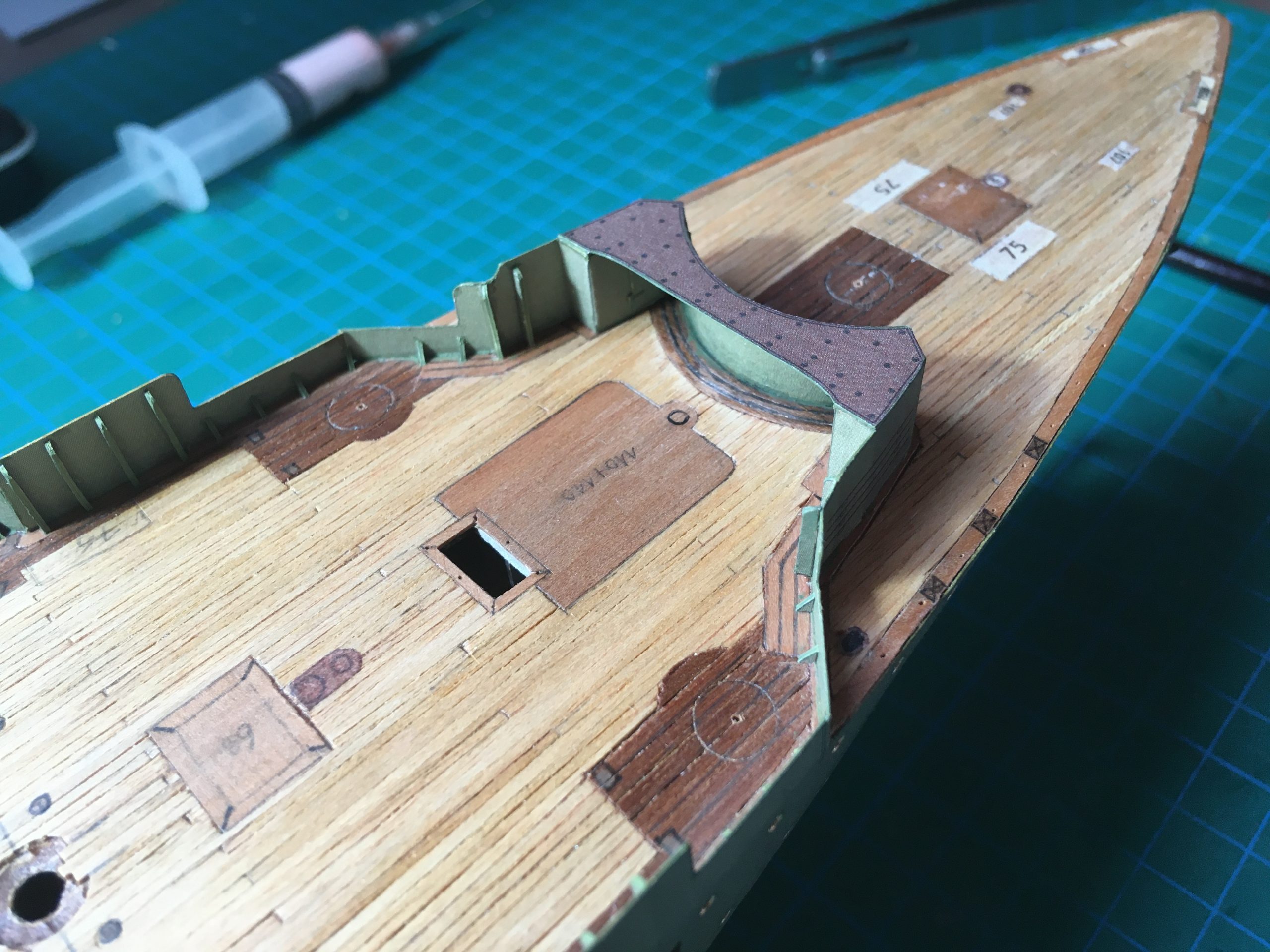
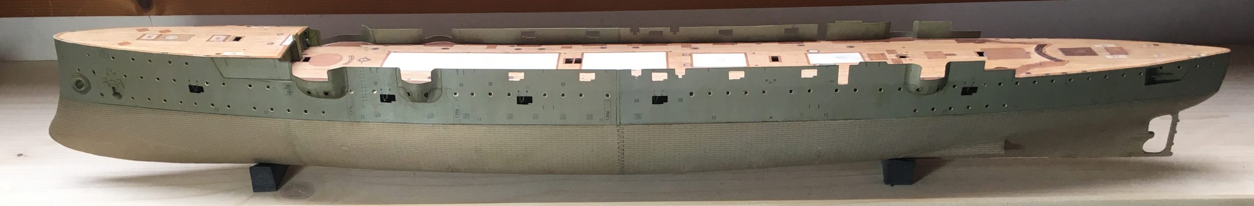
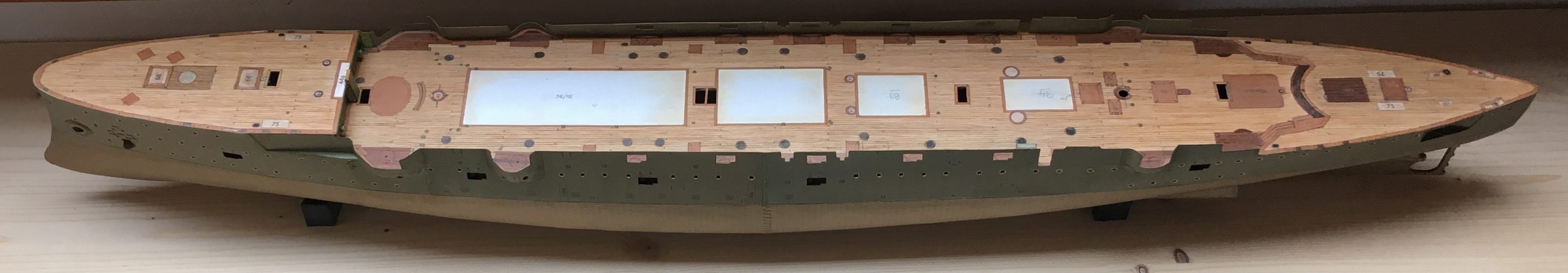
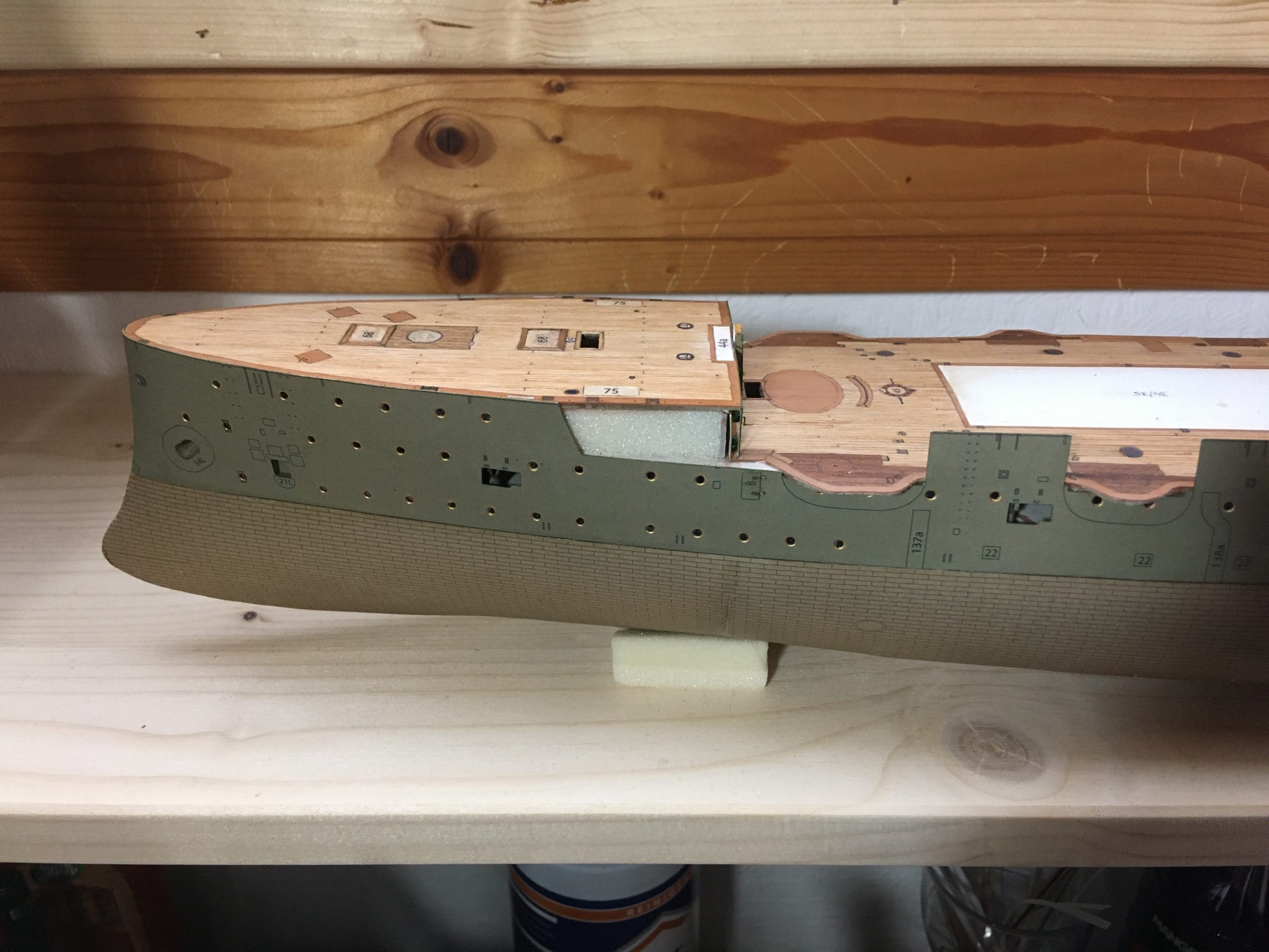
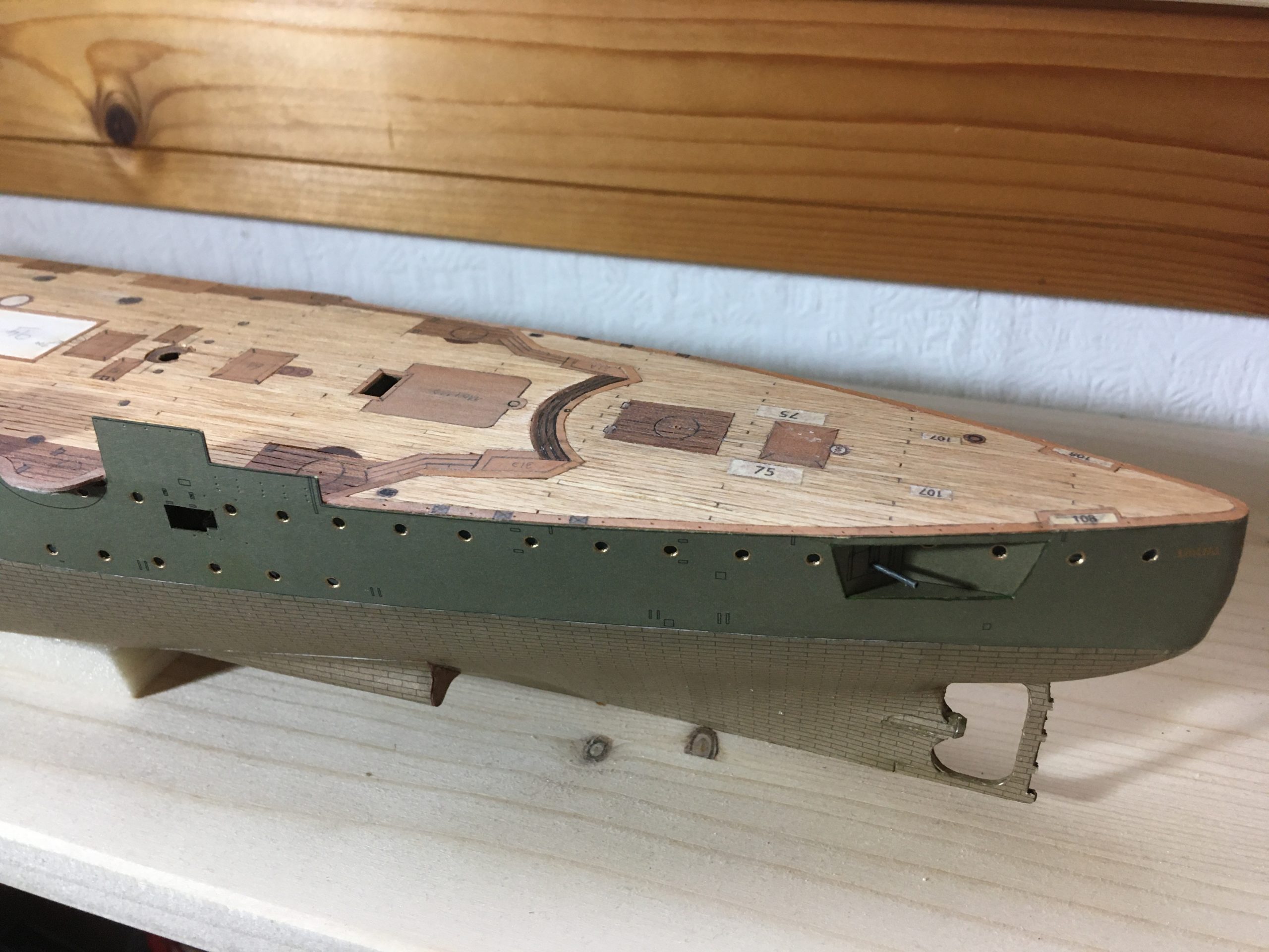
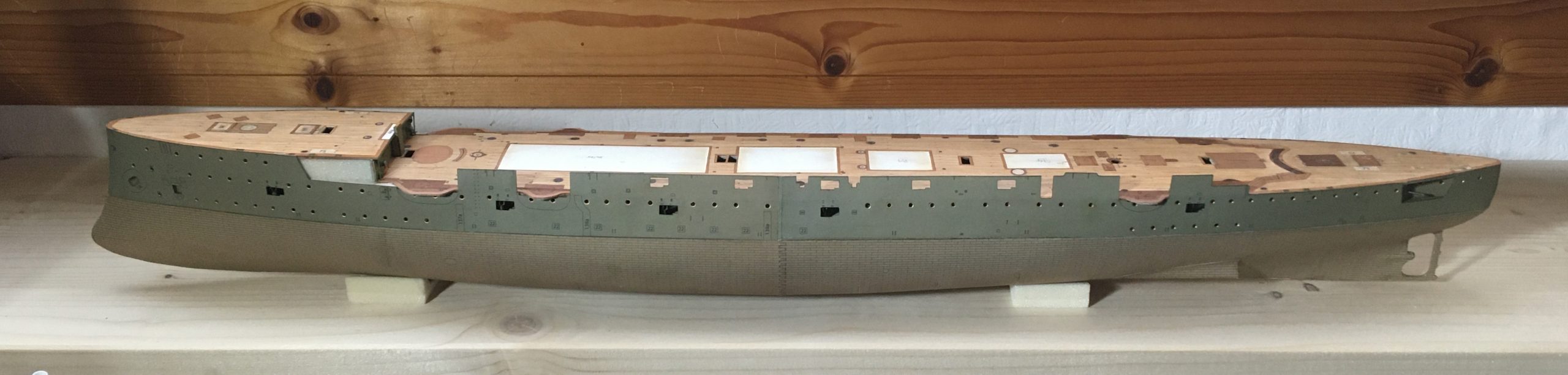
The finished deck now looks fine glued in place:

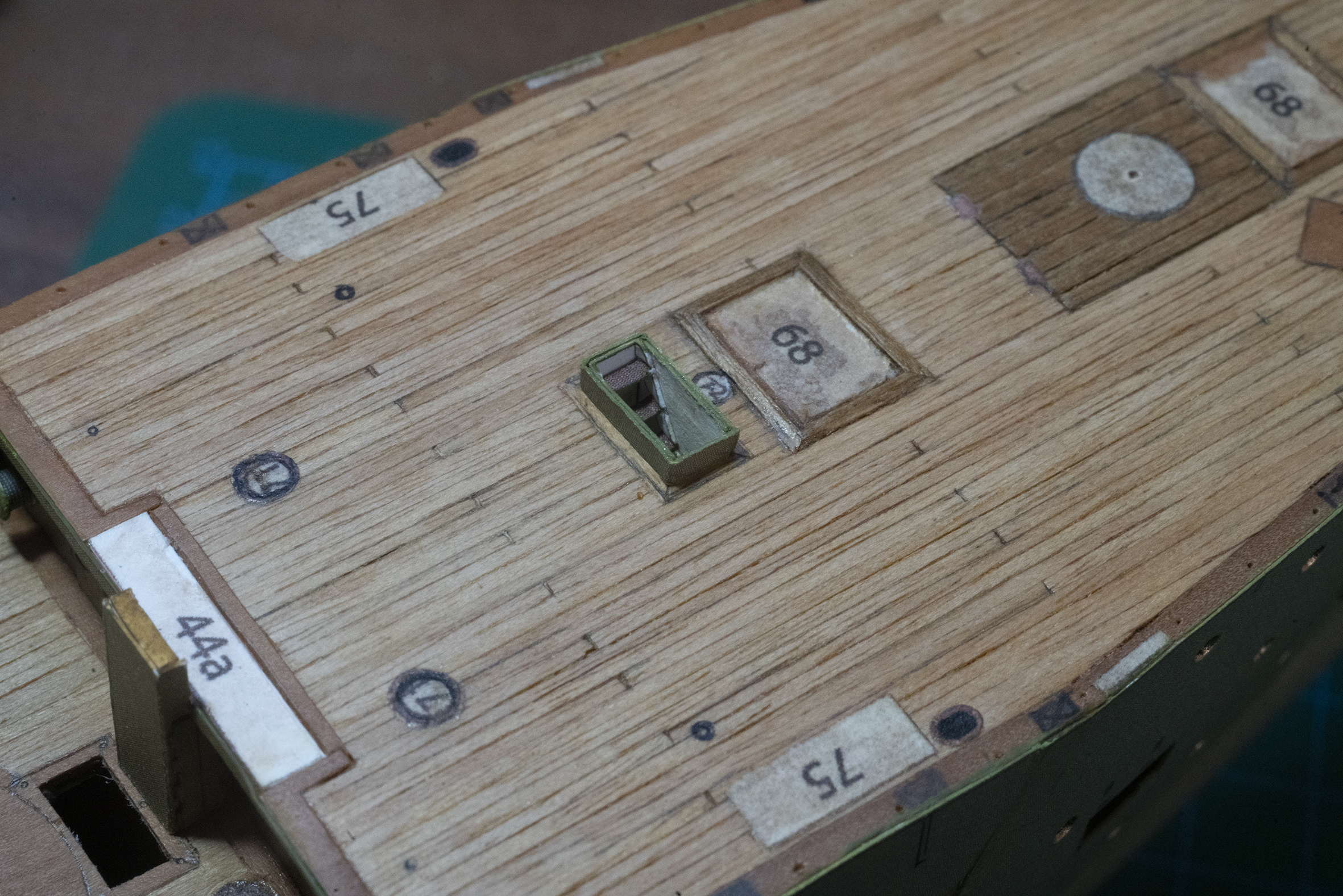
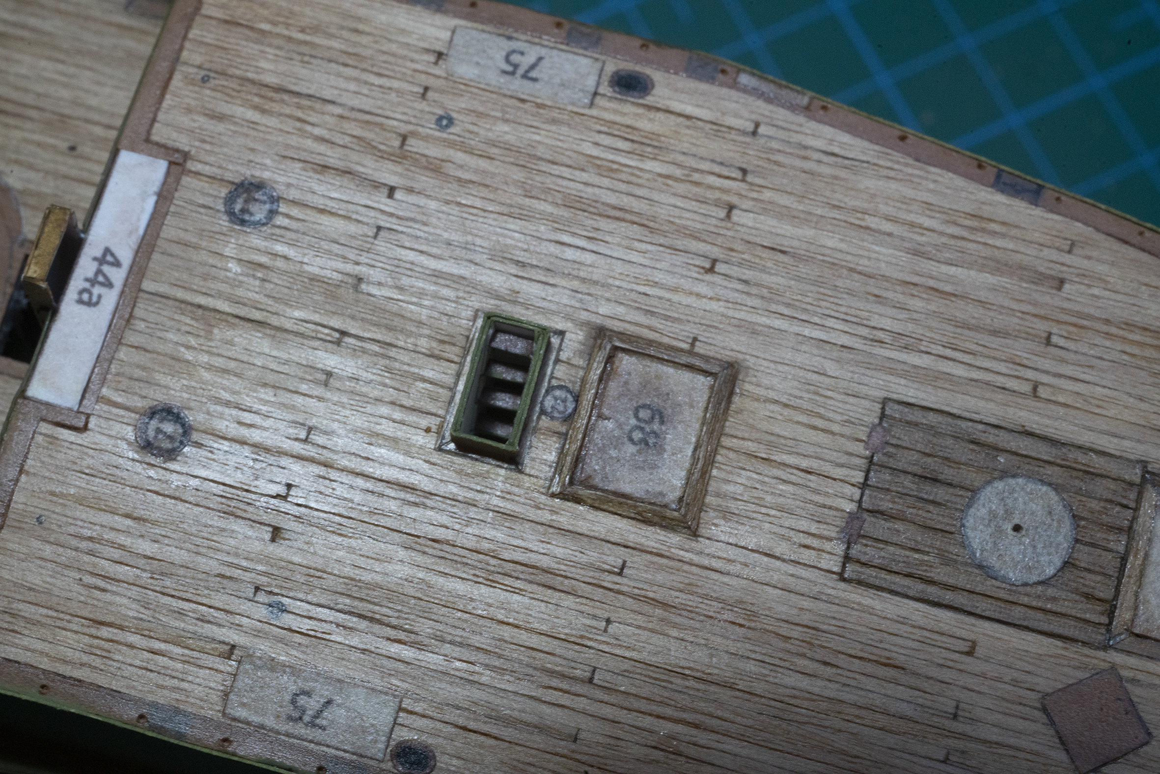
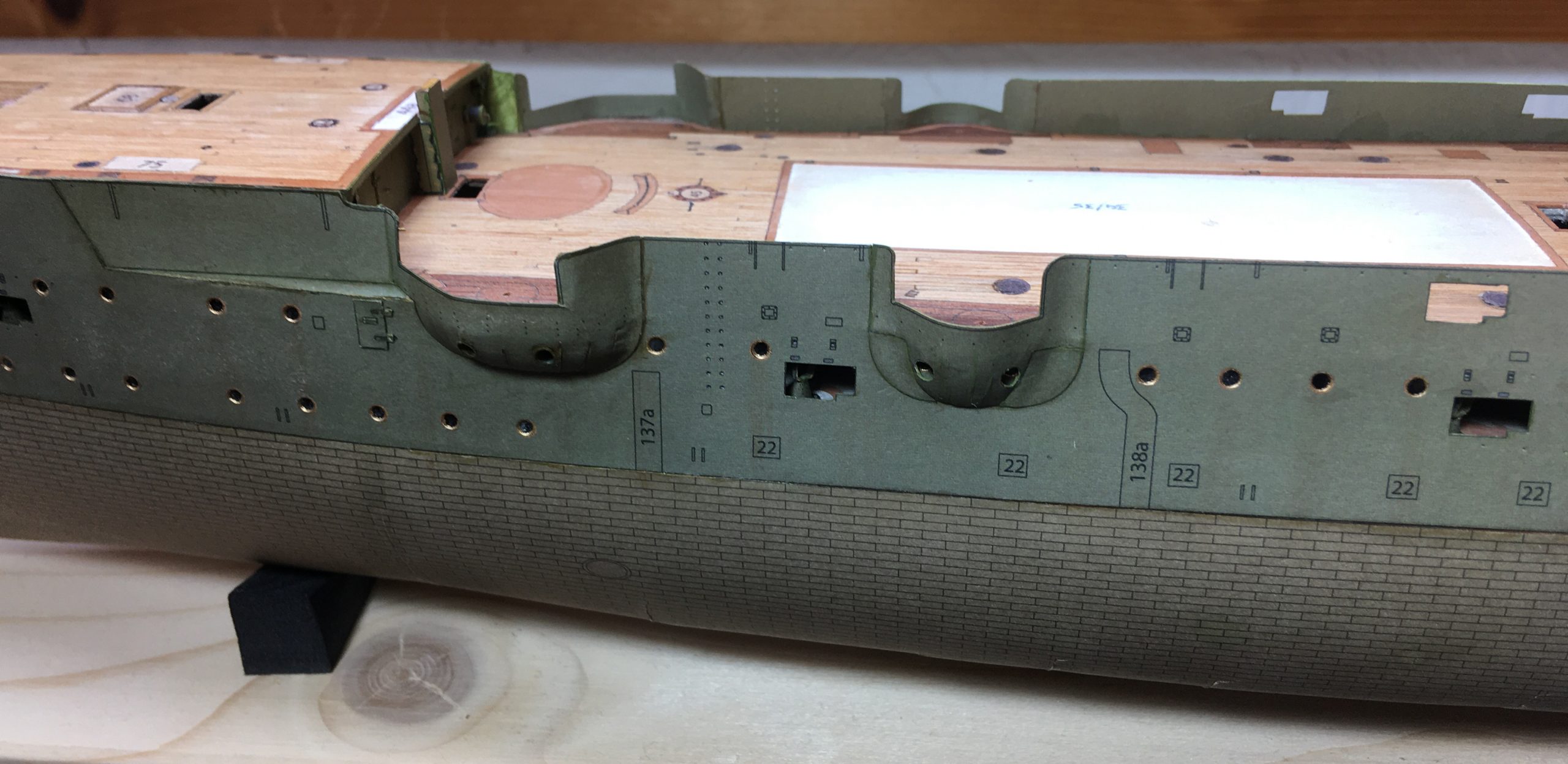
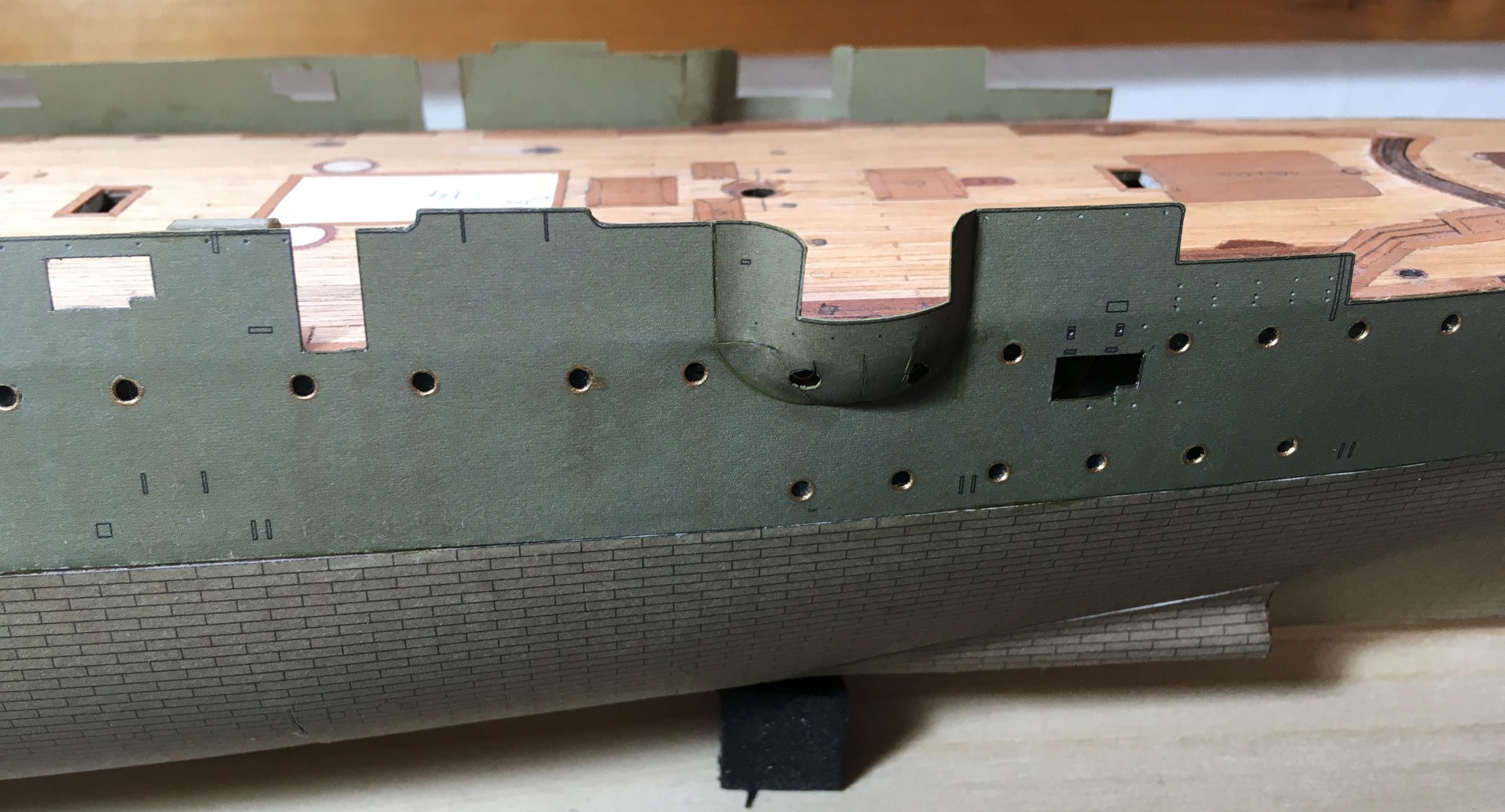
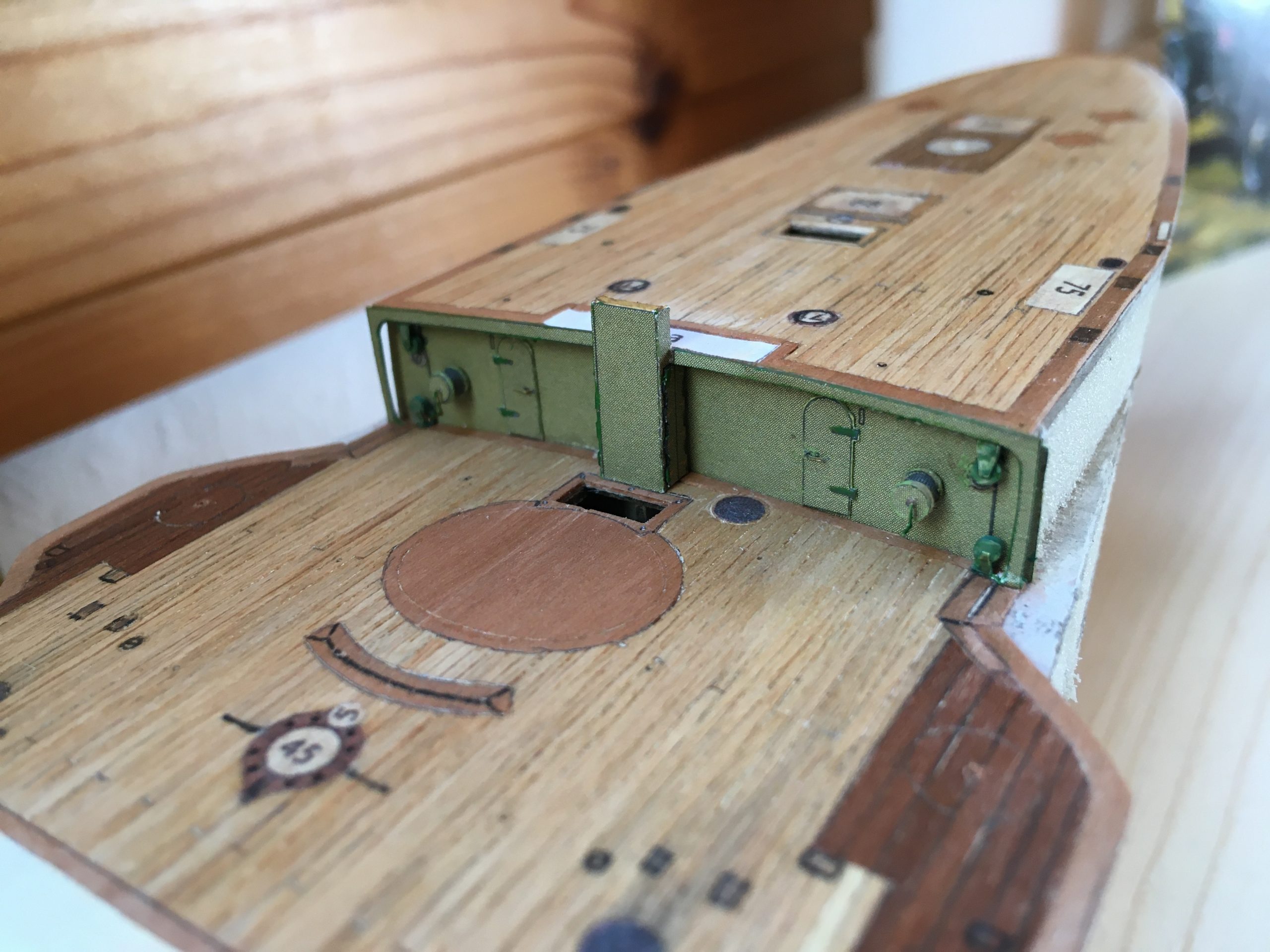
Some close -ups showing the laid up decking:

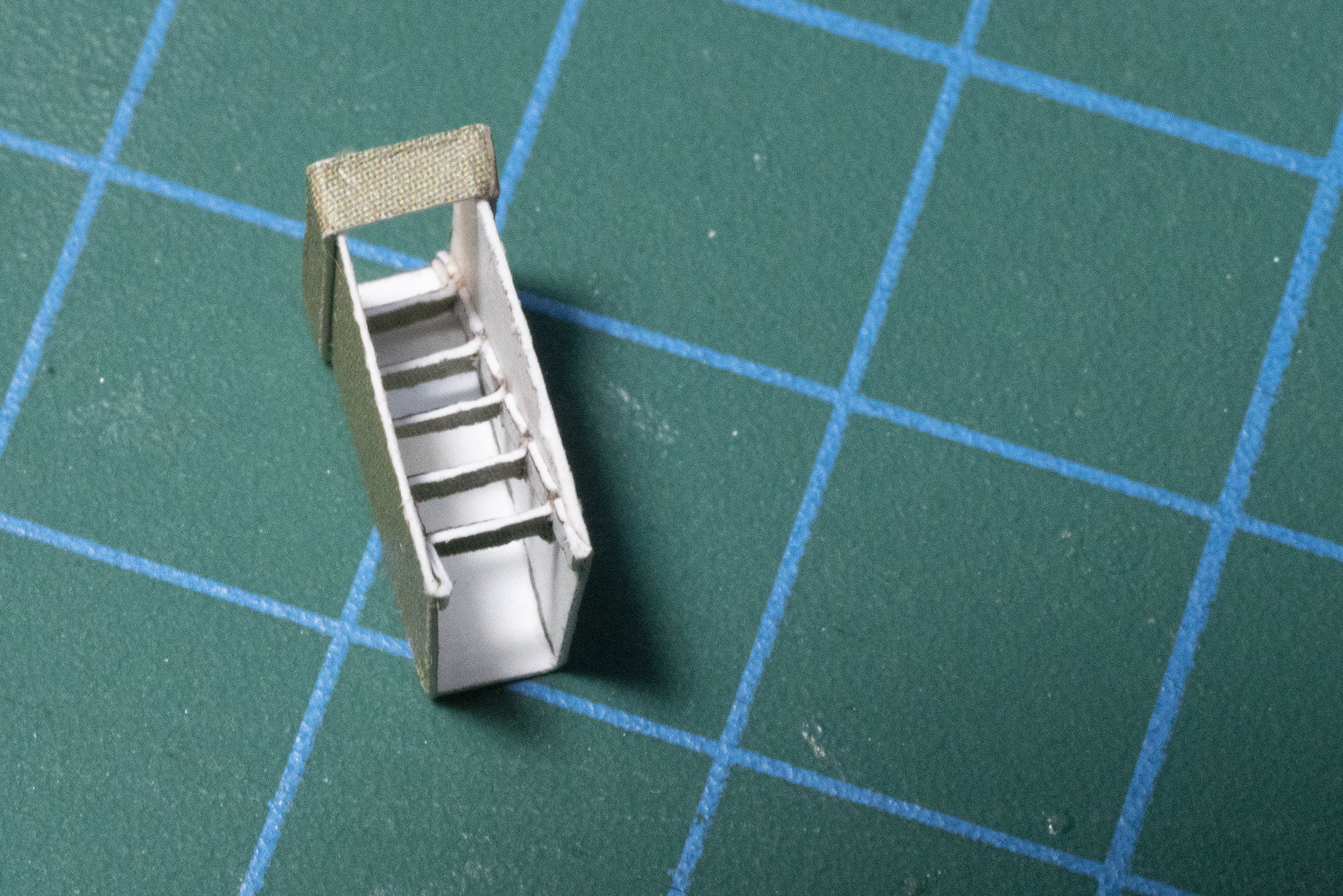
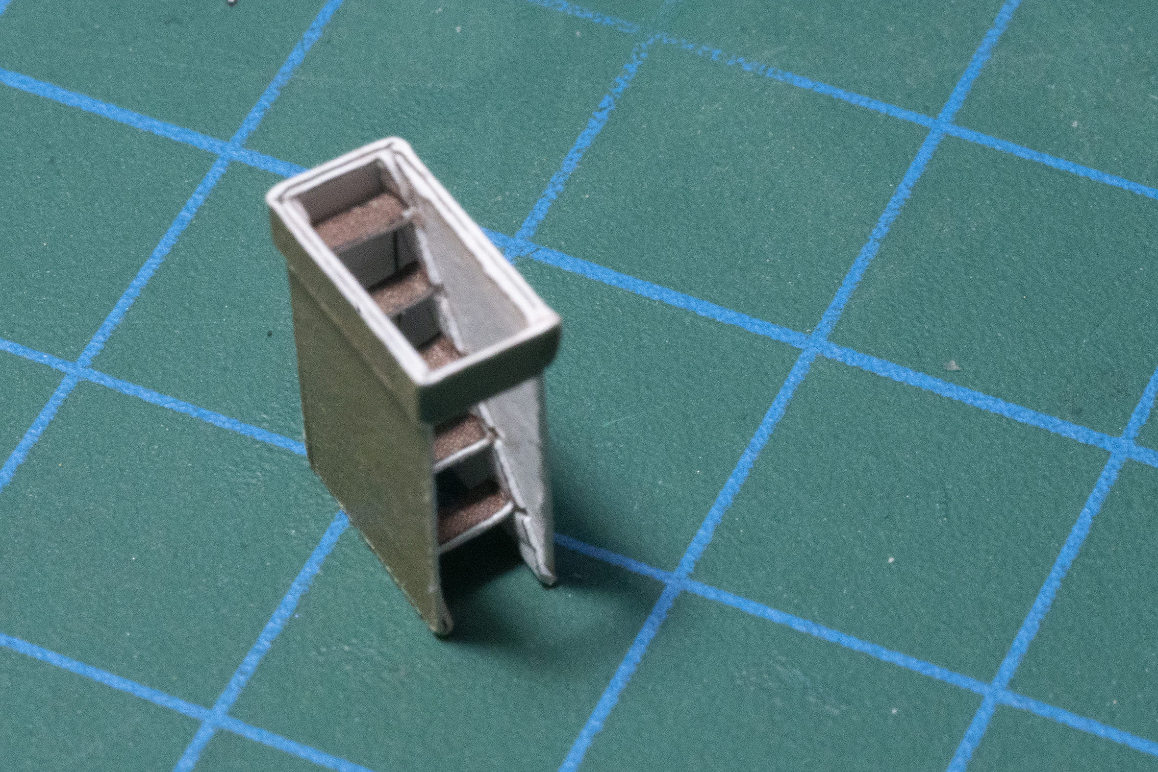
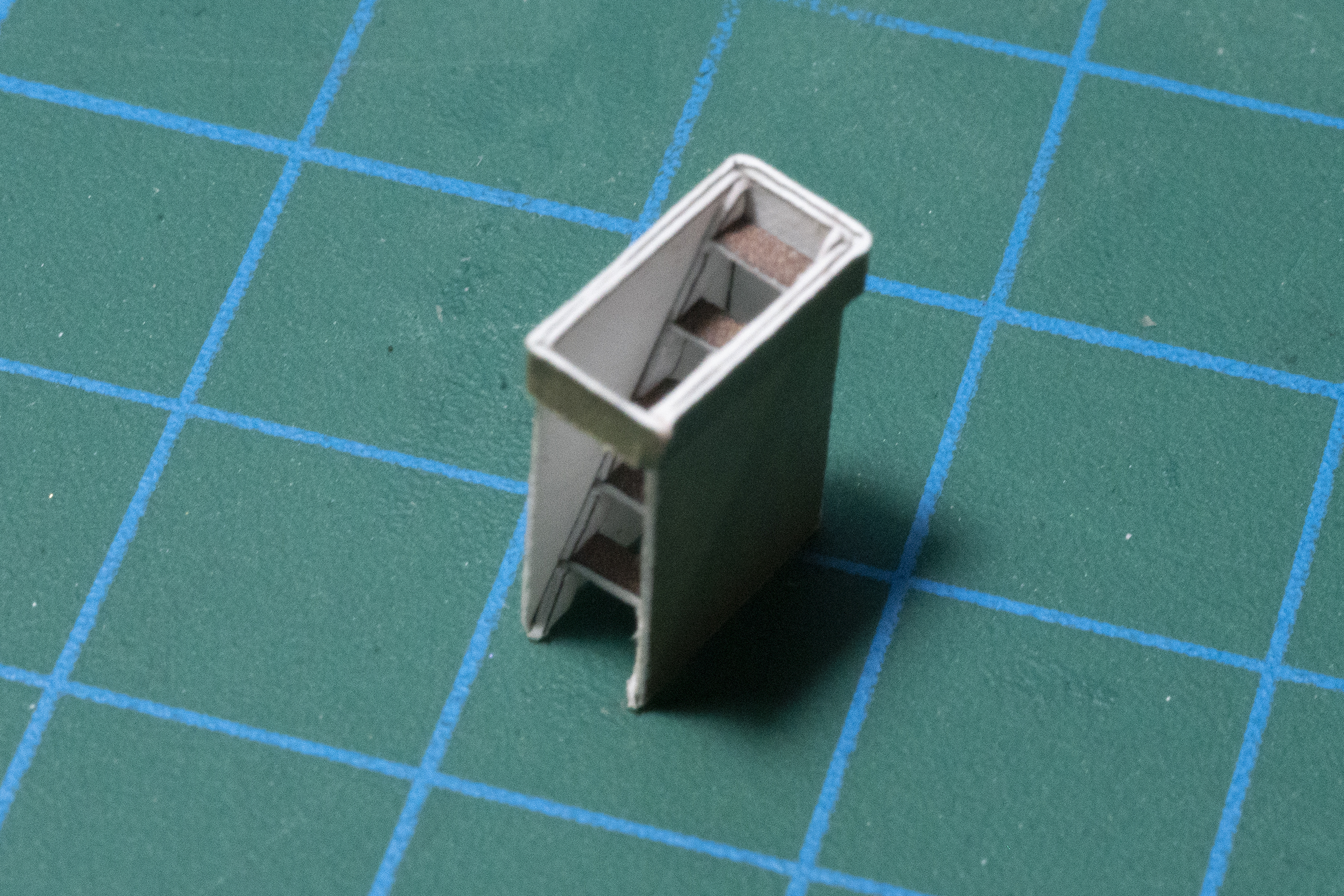
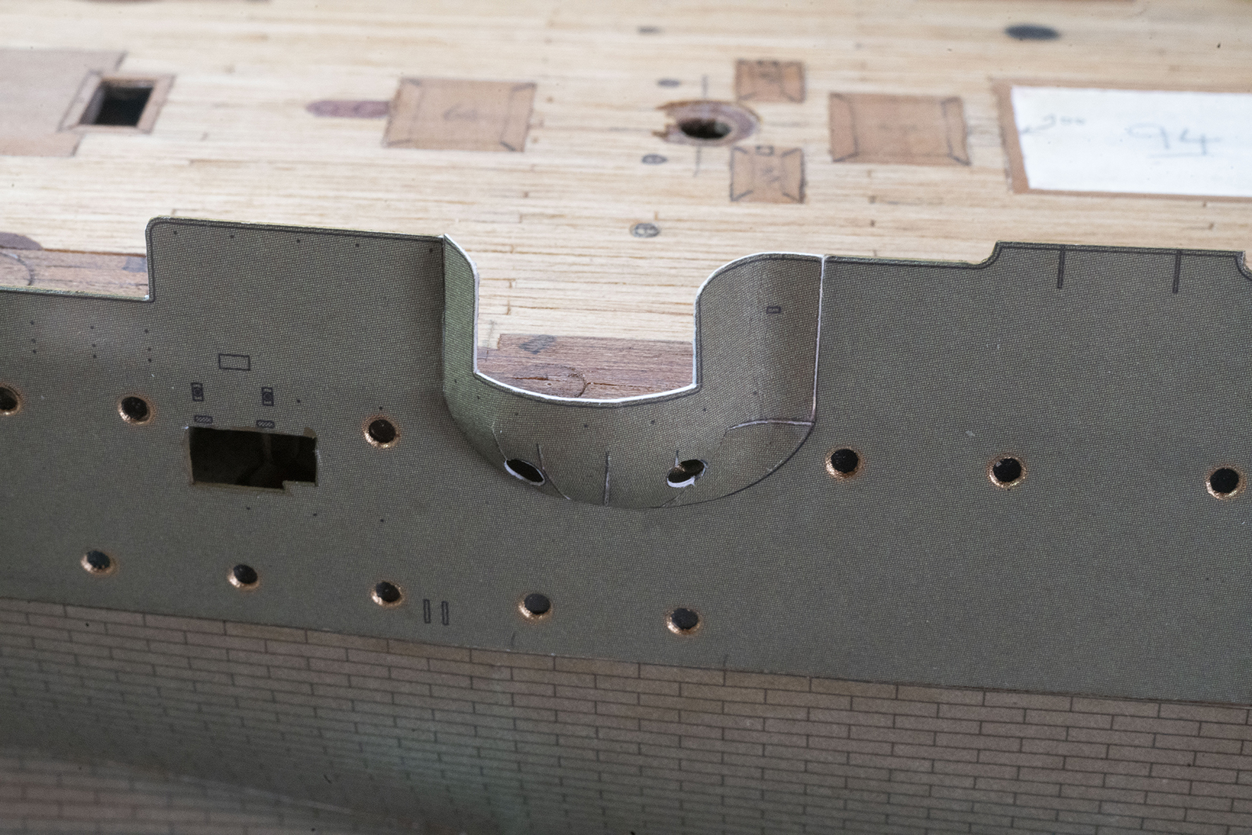
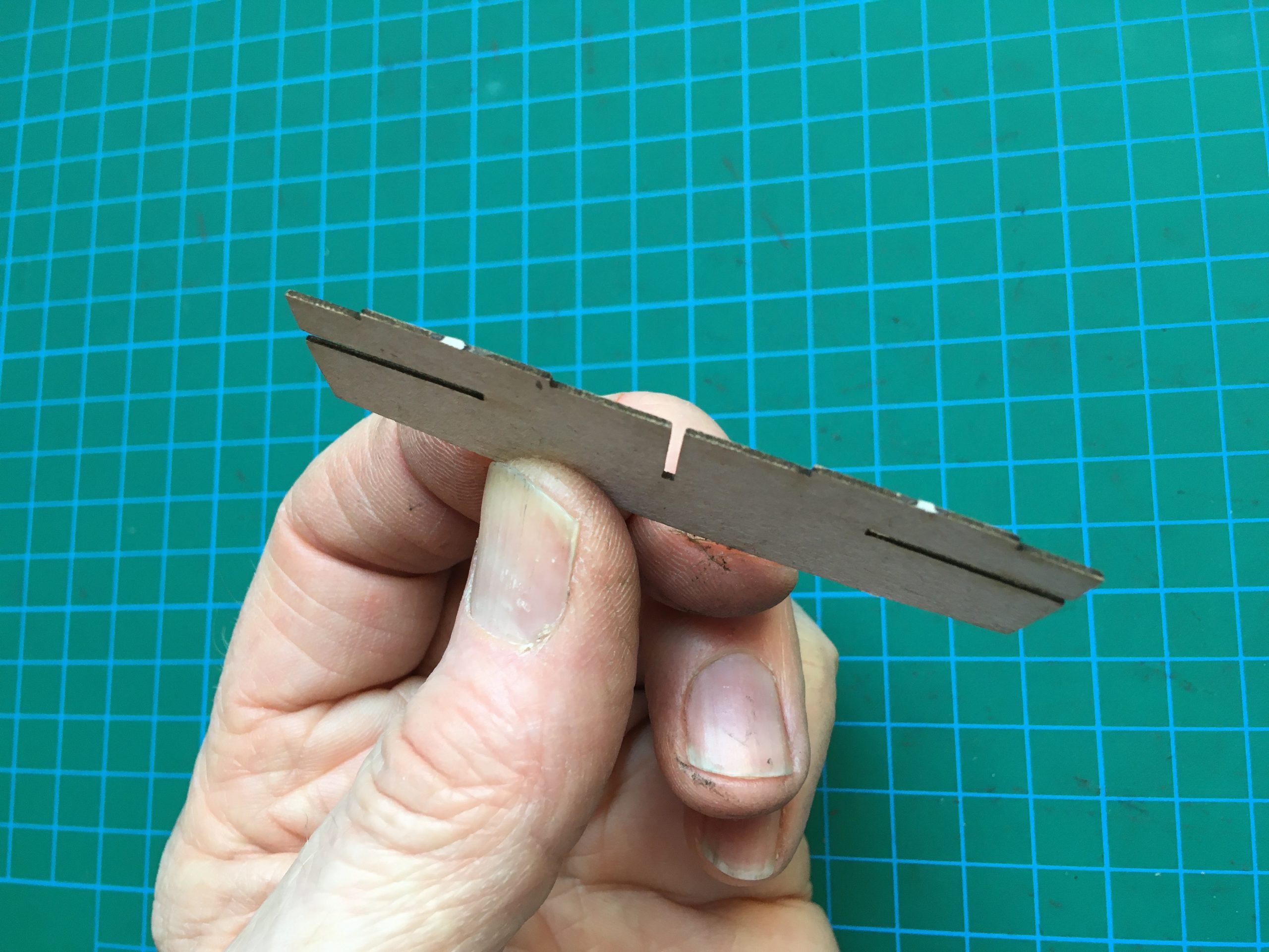
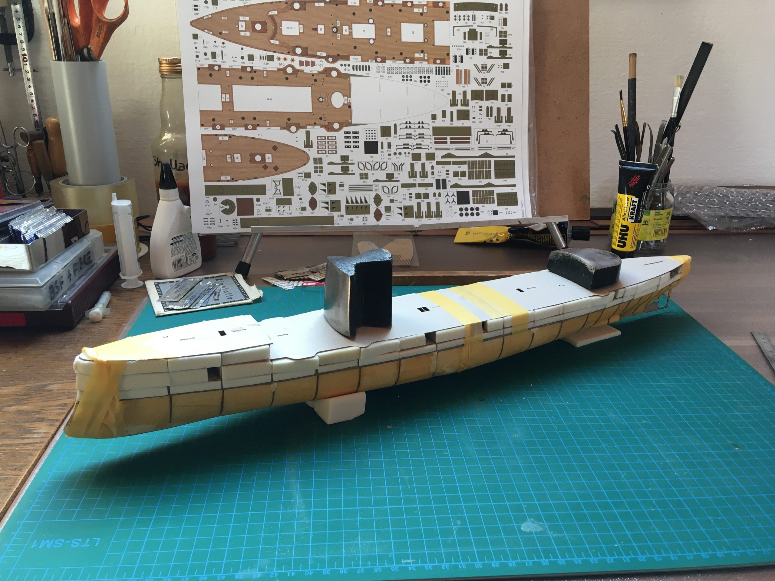
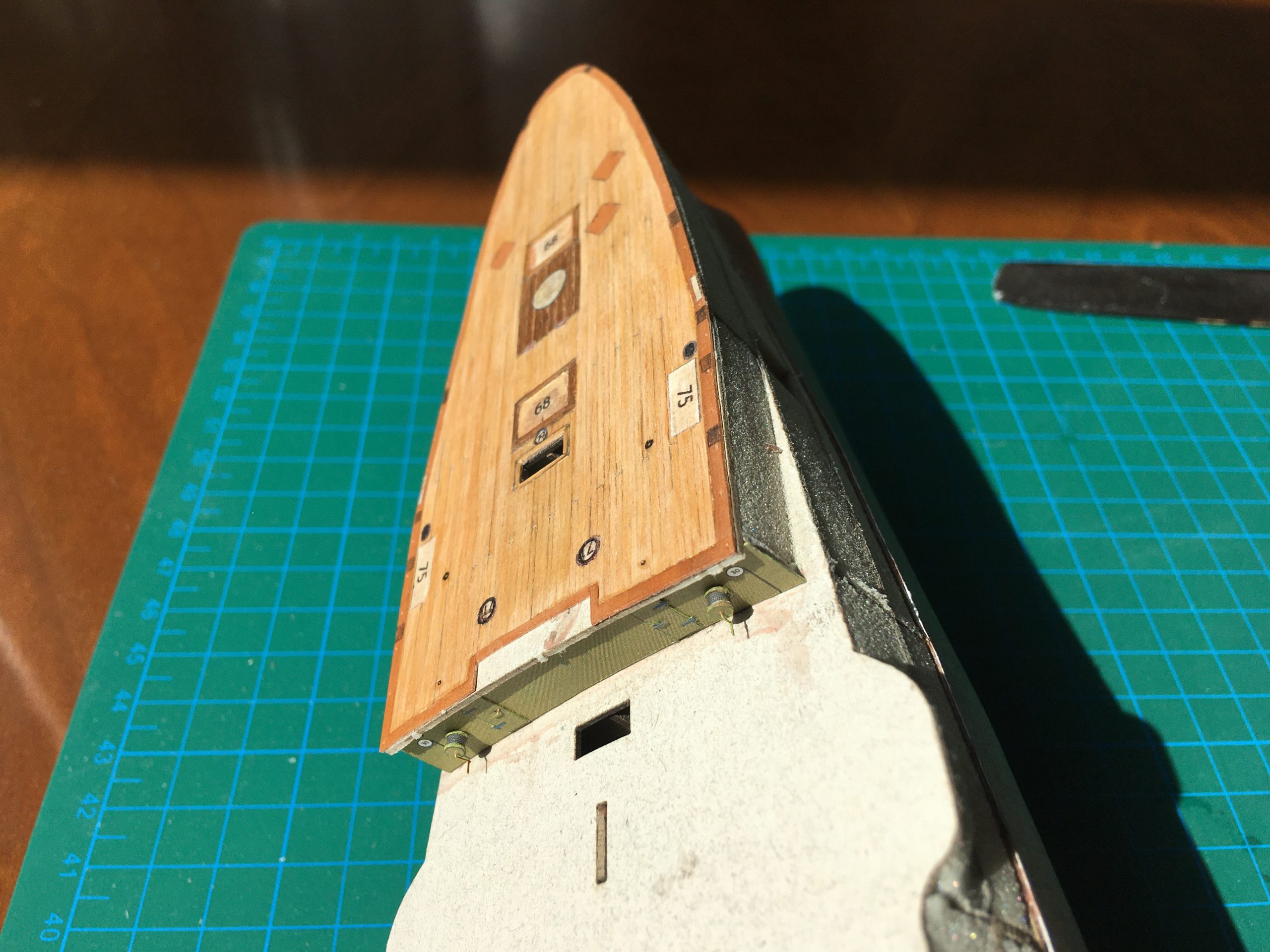
The foredeck fitted + the entrance to the deck below – just trying for size before fitting the main deck.

For the full report, please go to https://thingummybob.com/modelmaking/building-dom-bumagis-diana/

Building card-model ‘Diana’ by Dom Bumagi

I decided to get back into paper modelling at last and chose to start the ‘Diana’, which I bought while living in Ukraine in 2015. I have a number of (unmade!) models of the Pallada class In 1:200, the other ones are all of the Aurora depicted in different build years and by different companies, Polish, Russian and now this, Ukrainian, one.

Looks very impressive and I have not yet built one of their ‘super-detailed’ models, so here goes!

This is actually only my second warship in paper, my first having been the Ark Royal by ‘Maly Modelarz’ probably twelve years ago… a very satisfying build and an impressive display piece, despite its comparative simplicity. That one was stolen (!) during a break-in in 2010. I did have a go at another Russian ship of the line, Bogatyr, but that was damaged badly during the build and had to be scrapped last year 🙁 Up until now I had built quite a few aircraft, which made very pleasing models (but take up a lot of space ) and so I started a  sailing ship , the ‘Coureur’ – still work in progress and the SMS Götzen, which is undergoing a conversion to it’s present livery and build state as still used in Africa.

Regarding the Diana, I’ll skip the history etc and go straight to the model.

I decided to buy the laser-cut frames to save time. Nice is that it can be built either as a waterline model or complete with the hull below the waterline. I didn’t think to compare the laser-cut to those printed As templates in the sheets, I’ll definitely do it the next time, though. The reason I say that is, the width of the laser-cut profiles for the hull below the water-line was wider than the parts for the upper half. Not by a lot, but definitely so. A little less than 0.3mm all round, which is thicker than the card for the hull covering, which will leave an unsightly step? This also means probable trouble fitting the top half of the model? The frames fitted nicely together and were unproblematical, bottom and top halves being made separately, checking them regularly for squareness.

Each individual part of the frames is trimmed and sanded prior to assembly after cutting free, so there are no ‘nibs’ sticking out where they were cut from the card carrier-frame, which would possibly distort or ‘grow’ the assembly unwittingly.

Having glued them up and left them to dry, I filled the hollow frame of the hull with a new material I wanted to try out, but which it turned out is very messy (it leaves a fine dust which sticks to everythingand is too soft. Can’t even remember what it is called, but it was used at the wharf for coring out the reinforcements in the hulls. I shan’t be using it again. Below, you can see that the left hand side is finished and the right is not! It is also visible that it is subject to crushing and therefore difficult to glue.

After sanding the hull to shape, I then filled out the upper half above the waterline (NOT sanding it to shape yet), glued the upper and lower parts together put it all aside to dry and settle:

The next stage is the ‘copper’ hull: Not perfect, but doesn’t look bad either 🙂

For the full report, please go to https://thingummybob.com/modelmaking/building-dom-bumagis-diana/


New old Minoltas

Here are a few pictures of and comments about the recent acquisitions I mentioned in my last short blog.

To start with, the black SR-1 (d) complete with its correct lens (with the black rear ring on the mount). Nice condition but needs ‘a bit of work’: The first curtain runs fine but the second does not follow… and the mirror stays in the up position. Cock the shutter, the mirror drops and the same happens again.


Then another back one, this time the Japanese market XE, fitted with a contemporary lens, which works fine and accurately. Will get a clean inside and out and then run a test-film:

Then there was this 1949 Minolta-35 model D that I came across, one of about 1,900 made. OK, so I bought a Rather nice later 50mm 2.0 lens (about 1954 manufacture) to use with it, please forgive me. I’ll keep a lookout for the ‘correct’ 45mm 2.8, but in the meantime this will do nicely for my test shots to check the accuracy of the shutter. The third picture shows the small piece of the leatherette covering that is missing, which is invisible inside the case, which I will initially be making myself, especially in view of the larger lens 🙂

Minolta produced the earliest cameras with a central ’hot’ flash-contact in the shoe (introduced on the first -35 model A). They interestingly replaced it with a cable-connector on the next, ‘E’ model of the Series and with a coax connection à la Leitz on the model ‘F’. The ‘D’ model is purportedly the first with flash synchronisation (for bulb flash only, electronic flash synchronisation was first added to the Minolta-35 model II) but I find that hard to believe. Canon only offered Flash synch two years later in 1951 with their Canon IV.

Plenty going on

At the moment there is too much going on all at once… We are moving in the next month to Spenge in NRW, as a result of my having work there with a previous employer – for more money. OK, there won’t be more left over (rent is higher), but everything else is altogether more convenient and closer to three of my four children 🙂

On the camera front, my Minolta-35 D model turned up and is having a good looking at at present, still waiting for the lens and I’ll be picking up a black SR-1 (b) and a nice black XE, too in the next few days, photos to follow, not sure when – beginning to pack in between working, eating and sleeping!

Removing the top of an SR- camera safely

The whole SR series of cameras from Minolta are similar in their construction. The only departure from the theme would be the SR-7, which has an in-built light meter and battery, but the basic principle is actually valid for almost any mechanical SLR (with notable exceptions, of course, like cameras with removable finders).

I have prepared a short video to show how it can be easily and safely done without doing any damage to camera or yourself. What you do afterwards I can take no responsibility for. I only need to access inside the top to clean the prism faces and check the cleanliness of the film-winding mechanics. In the case of a stuck camera, 99% can be done just by removing the BASE plate and adjustment or cleaning of the slow-gears are inside the mirror-box, as previously described.

Here is a link to the video, while I try to resolve the uploading problem that I now seem to have…

https://www.dropbox.com/s/wezkvi41sao6h2z/Video%2006-12-2019%2C%2014%2043%2017%20Copy.mp4?dl=0

The video will soon be uploaded, but first I have to do a light edit to remove my head from blocking the view… 🙂

Interesting for those that have never looked inside one of these, there are internal differences even between early and later versions of the SR-2, as demonstrated here!

This is an early model (1100783) and just look at this! The inside of the top pressing has been hand painted in black on the inside

Before wiping off, there is a little mould on the prism (corners masked off with black insulating tape) and the holding mechanism for the prism is very different to the ‘later’ models (as of when?) Clamped at the back and sides instead of the customary overslung bracket and springs, over a plastic moulding protecting the prism. (See below, both are SR-2s – the one on the right has the film transport partially dismantled)

The yellow arrows show the screws on the brackets to remove them, the red outlines the brackets somewhat…

This is the one that is accessible on the left – the one on the other side is not! This one only needs to be loosened.

Once having removed the screws and brackets, the prism has to be lifted about ⅛” or 3mm upwards to release it. Here is mine and, though not really very visible here, the specs that you can see are  fungus ‘spiders’ settled and spreading on the prism… easily removed with a 3%-10% peroxide solution applied with a soft artists’ paintbrush and a quick wipe-off – no costly coatings to worry about here, anyway! 🙂

Minolta RF Rokkor 500mm f8 sunshade

Well, I don’t know about you, but the pitiful length of the sunshade on both mirror lenses I have owned have always disappointed me… I realise that the coatings on these lenses are nothing short of wonderful, but especially mirror lenses are very sensitive not only to vibration, but also to adverse light conditions. So I thought I’d do a test. I made up a sunshade out of card and tested how far I could go without vignetting on the 500mm shown here. Believe me, I was surprised! The whole inch of the original sunshade was well under a sixth of the shade I built WITHOUT any sign of vignetting. I don’t think that anything shorter than the diameter of the front lens is useful or that anything much longer has any actual added benefit (I’m willing to be corrected on this), so I decided to improvise myself and use ‘easily available resources’ (i.e. without resource to a lathe) to make a usable and effective sunshade. Originally a little tongue-in-cheek, the finished product works wonderfully, was really cheap to make and is light and can store all sorts of stuff – even a lens – inside it in the camera-bag! Win-Win 🙂

The diameter of the lens makes it unusual, so getting one from another lens was out of the question. Looking around the house, I found a consumables tin that fit actually very nicely and also had he benefit of a plastic lid that would be handy as a lens cap! Originally filled with nuts bought from a supermarket (the same size is currently available here for the equivalent of £2.50), I carefully removed the bottom with a cutter and pressed/rolled the ragged inside edges flat with a cross-head screwdriver blade (anything metal or hardwood would do the trick) and put some ‘zebra’ tape (paper, actually) on the inside to stop it scratching the paint on my beloved lens… 🙂 At this stage, the functional work has been done, as it now slide-fits snugly over the front of the lens including the original sunshade and butts up nicely against the barrel, without being loose. I then decided that rather than spraying it matte black on the inside, that I would line it with black rubber foam sheet available at almost all supermarkets in their craft department in various colours. A strip 44mm wide is perfect, as it fits exactly from the front to where the original sunshade is and gives extra ‘Register’ there, to hold it nice and snug.
Look at the photos to convince yourselves of the fit and function – regarding the optics of the outside, perhaps you will decide for yourselves what is more appropriate. I went for a cover of thin, black leather, but matte black spray paint, card or anything else will do according to your taste; you could even leave it as it is (as I have for months!) or do a pink fur and Smarotzi-Diamond job on it! Enjoy!


To be honest, even the Original cap fits (as seen on the photo above), but the original for the tin is of course a perfect fit.

You May also have spotted another ‘modification’ that I have for this lens to take the light input down a stop, without having to swap filters in the back! I converted it to an f11 lens with a ring of the same foam rubber sheet as above (formerly tested with black card) which is cut to fit nicely under its own tension in the front of the lens. No glue, just fits nicely and doesn’t fall out an can so easily be removed or replaced, doesn’t get damaged or damage anything and doesn’t take up any space either! The doughnut-ring Bokeh ist thinner, of course, but for a quick and dirty solution, this works nicely. I can’t claim that the depth-of-field is influenced to any degree, though. Still, it does offer a bit more than just one ND4 in a pinch!

The case on the Sony is also one of my handmade additions, too, by the way. The top will be completed soon, too!

Here is the budget sunshade as finished and used at present: I could have used black thread, but, “what the hell”, I thought… 🙂

Dr. Peter is a frequent contributor to thingummybob.com