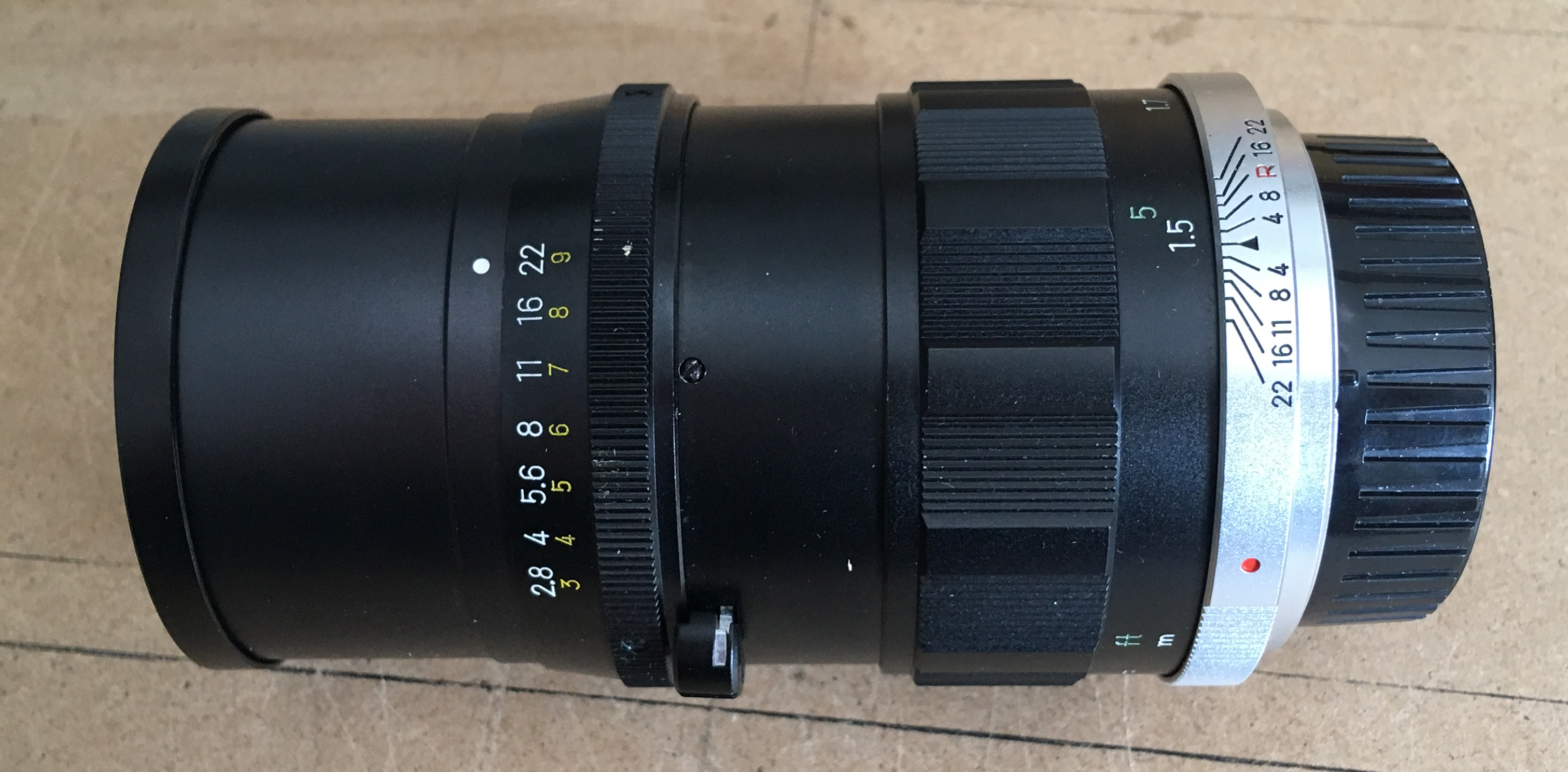
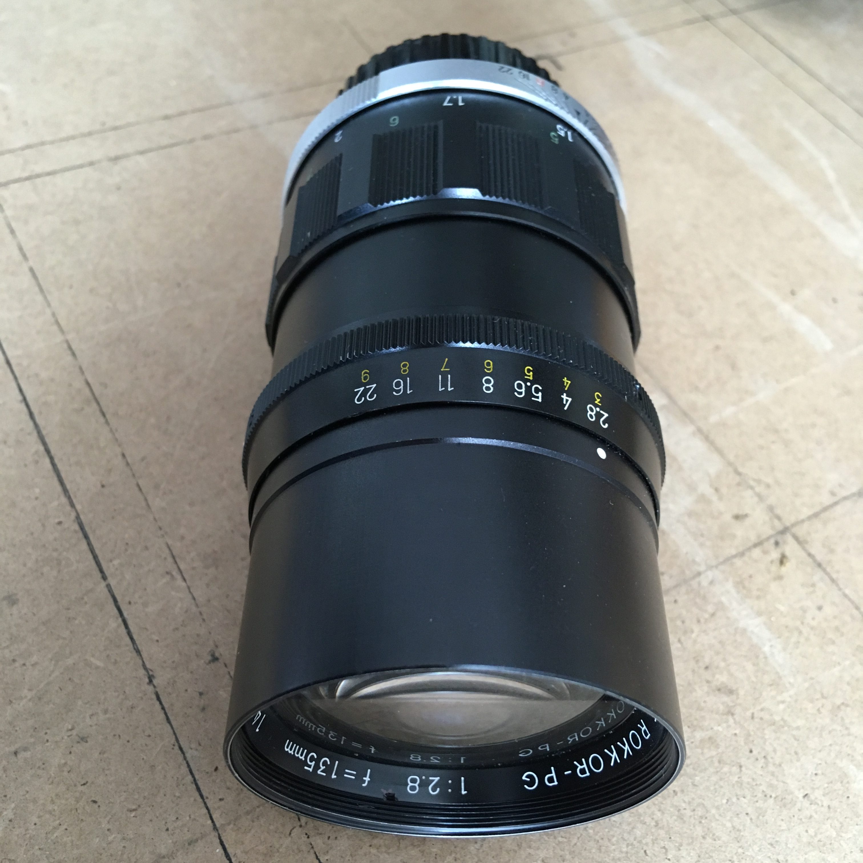
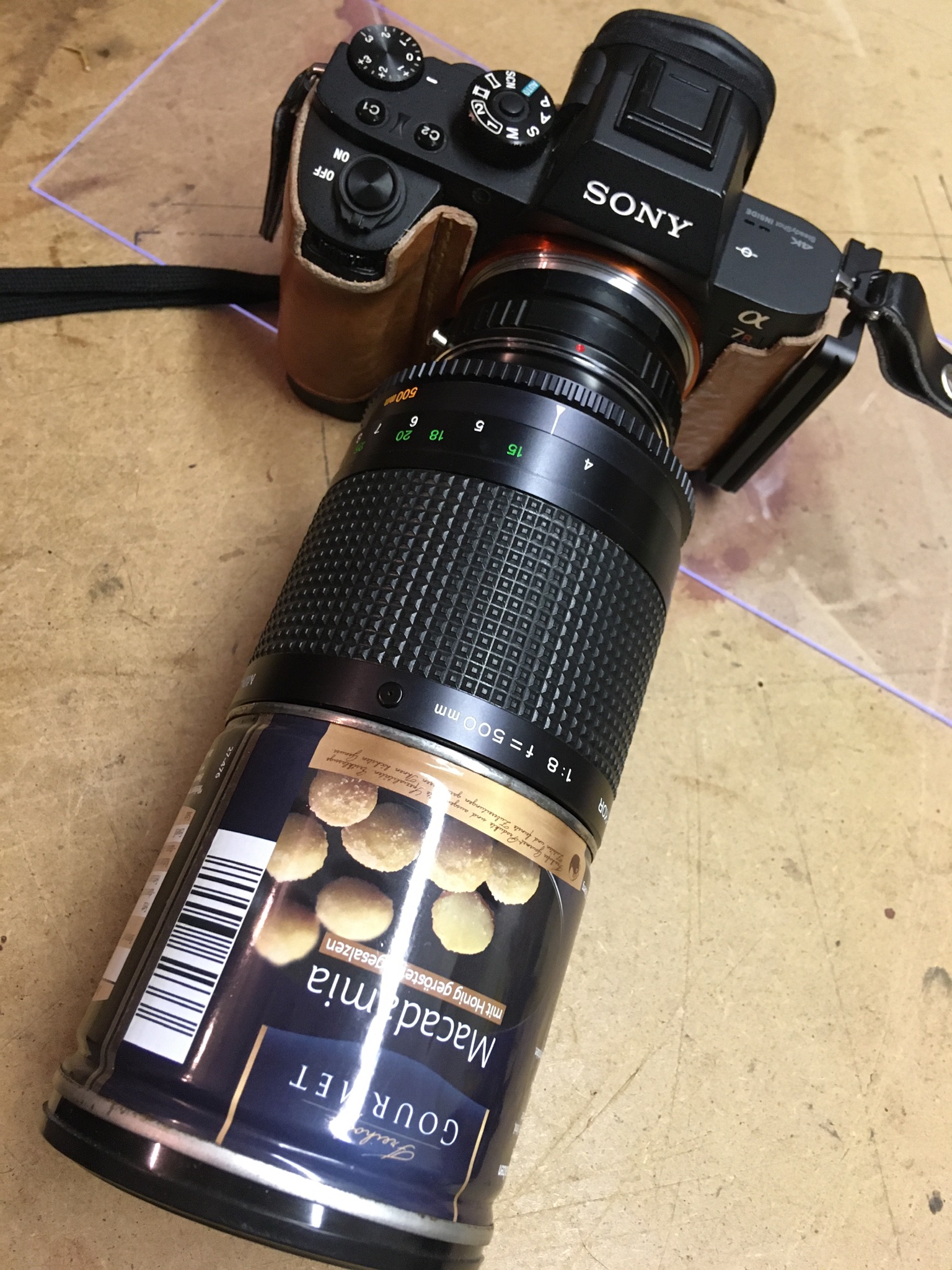
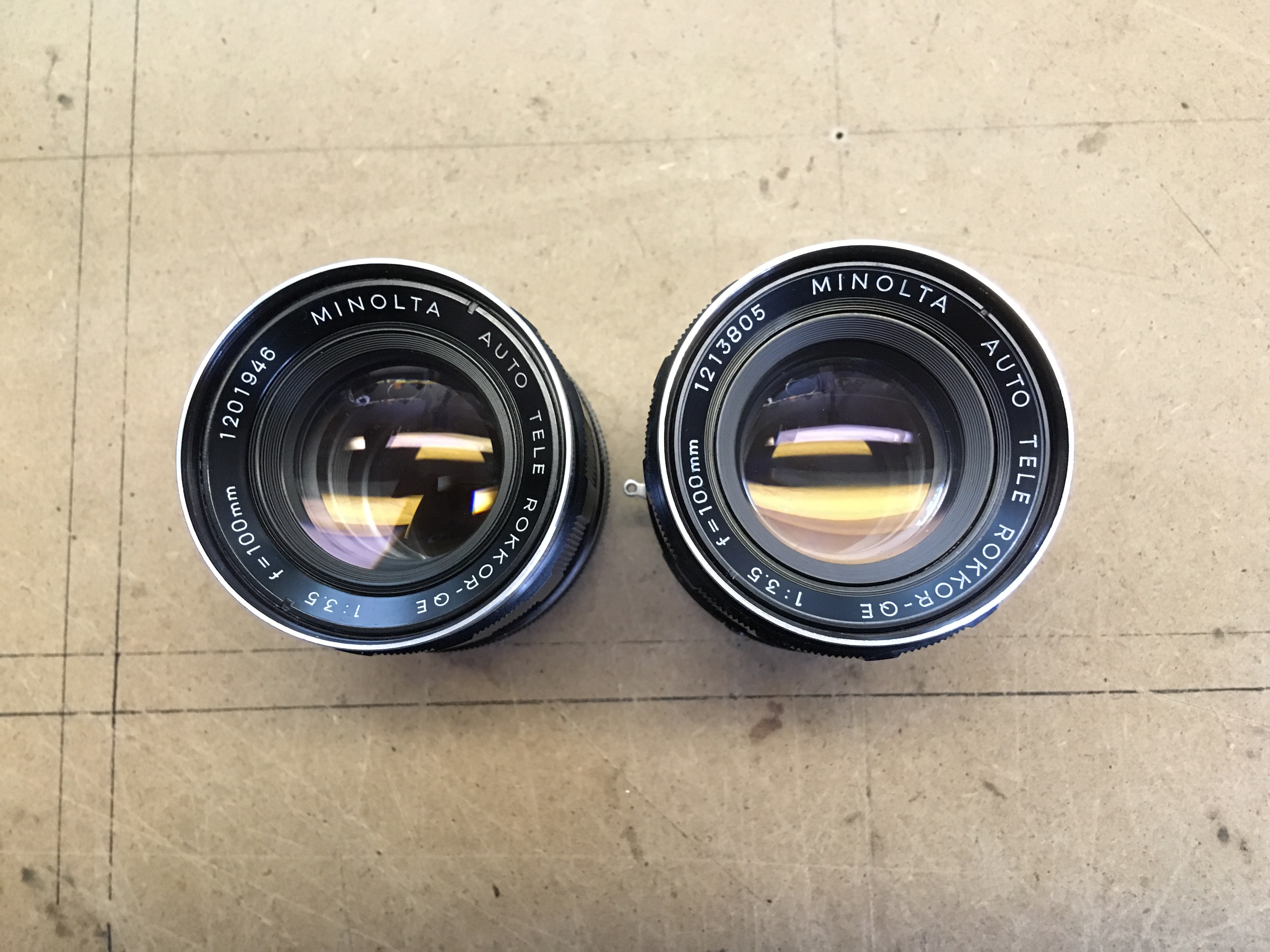
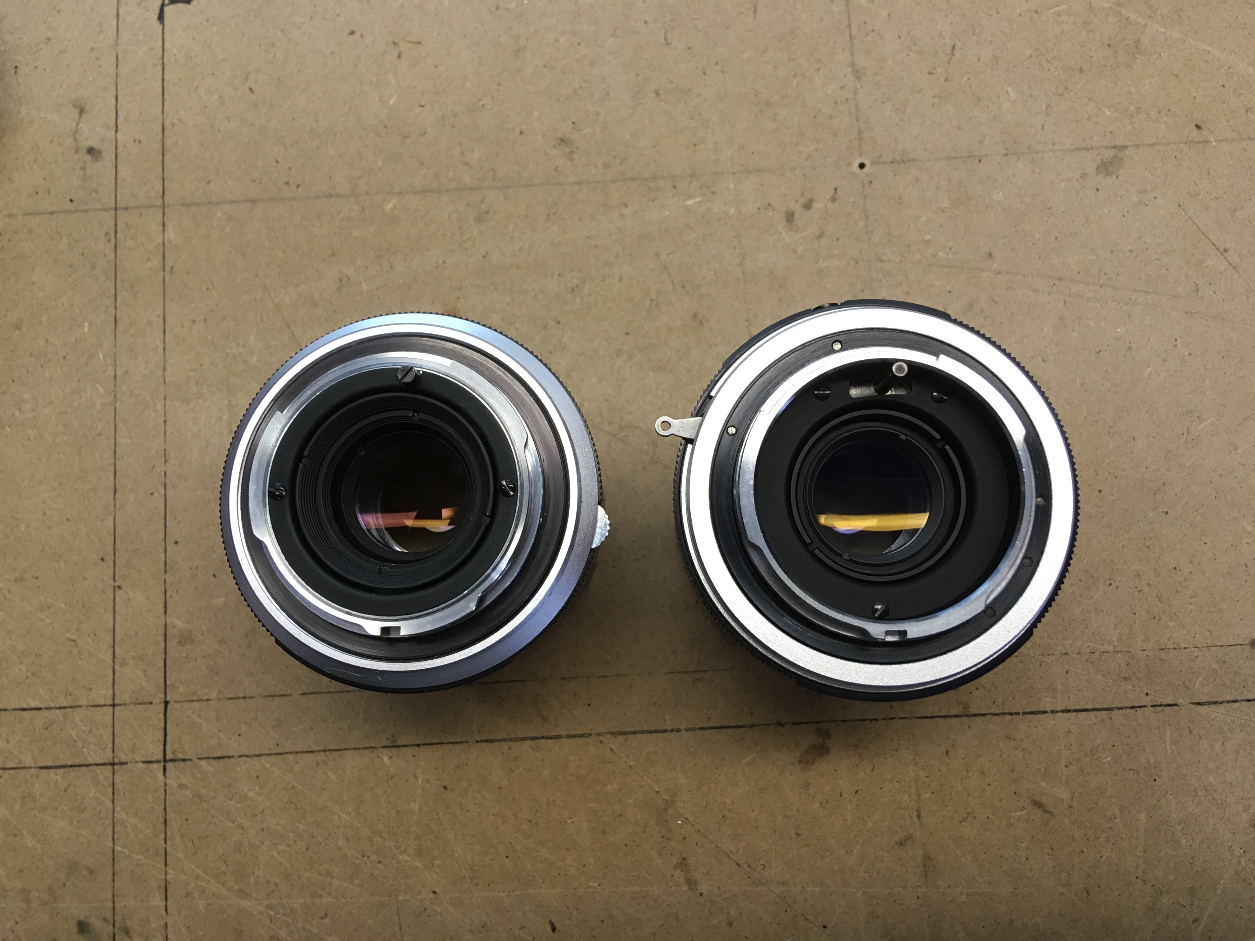
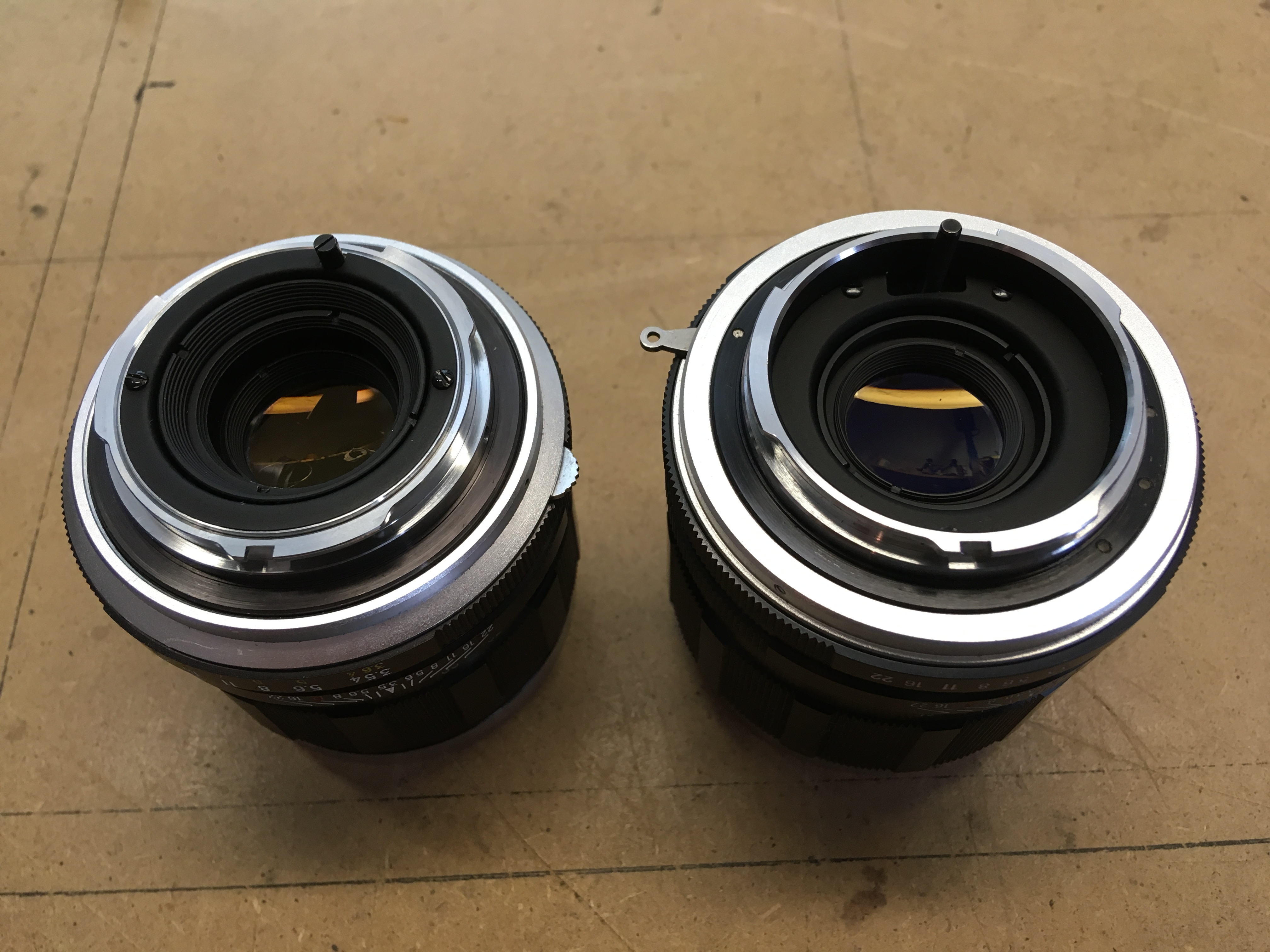
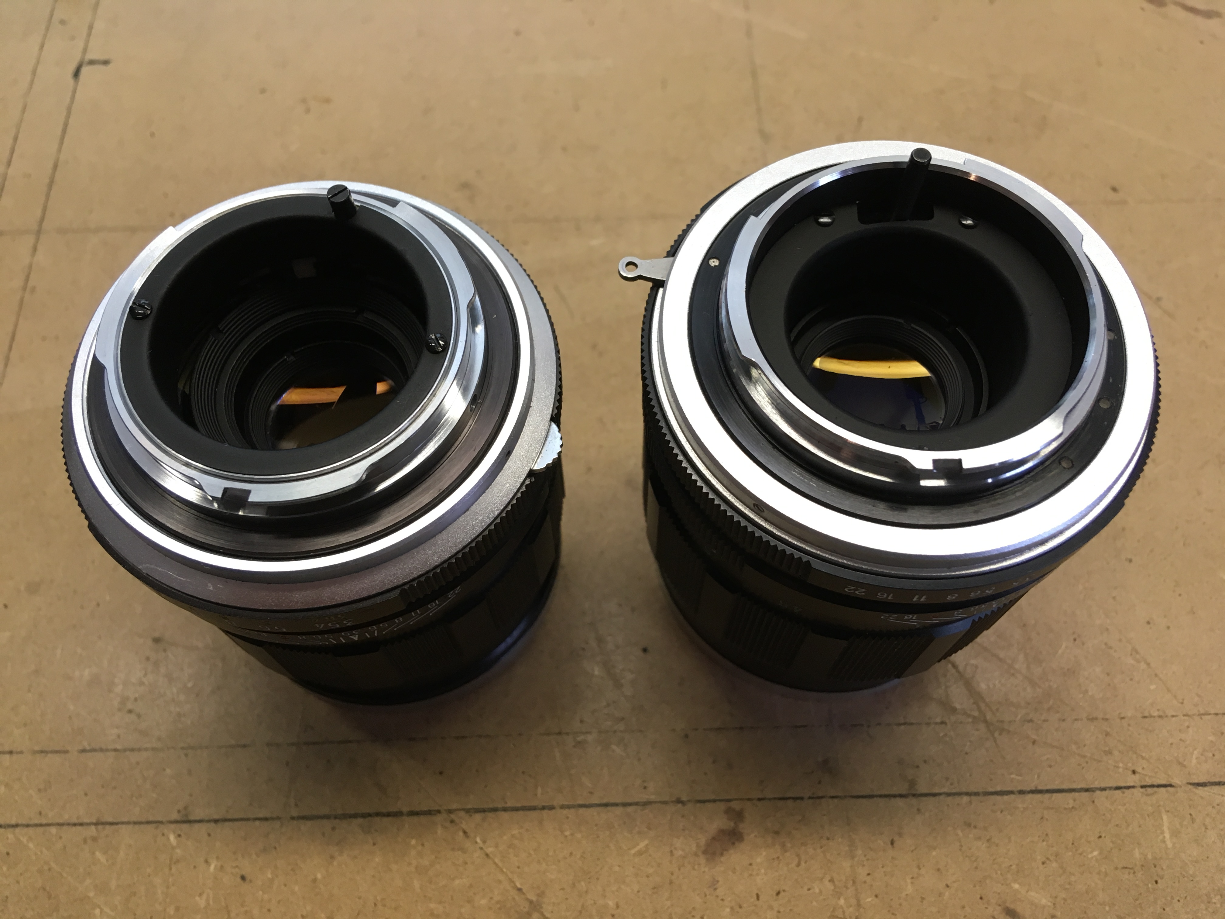
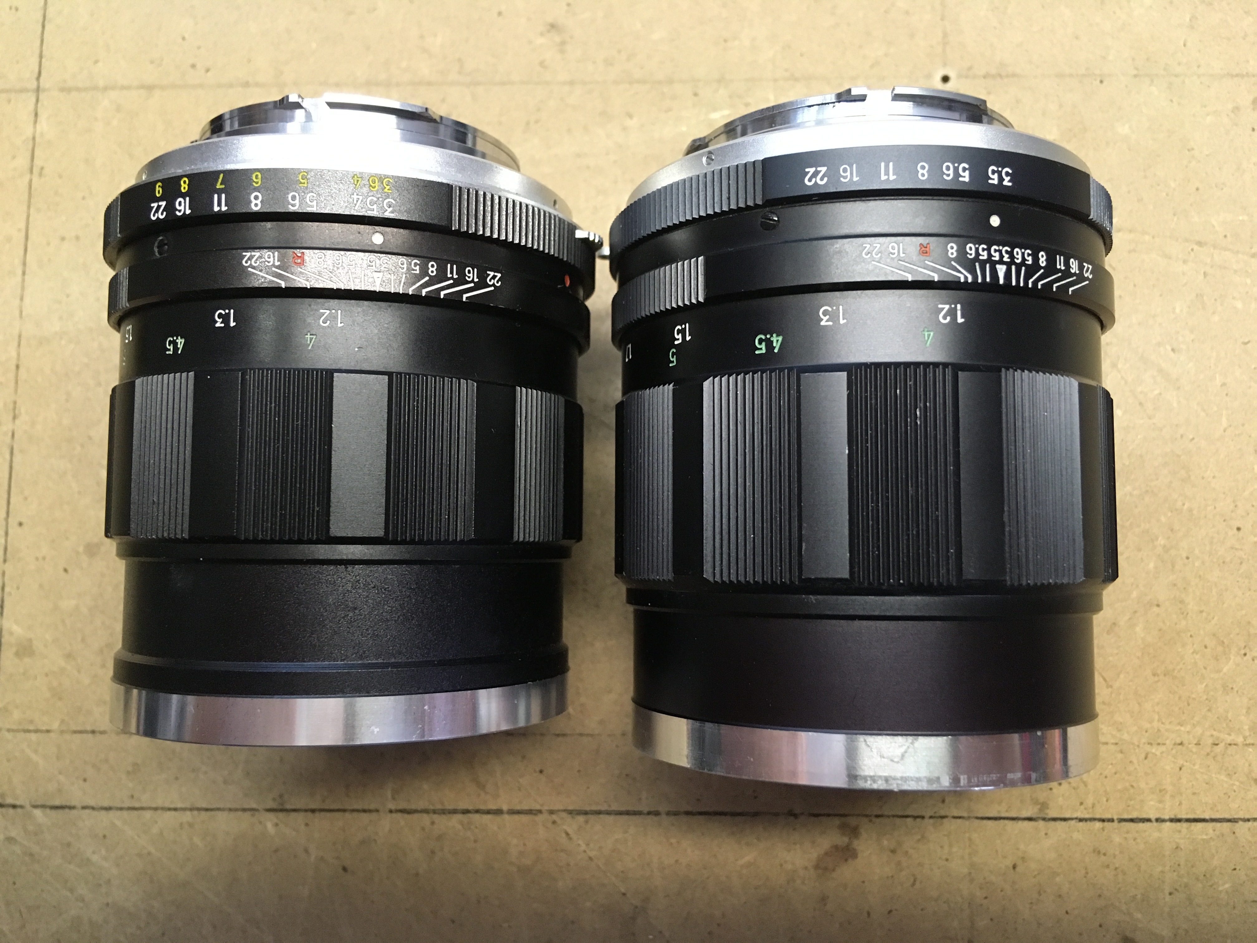
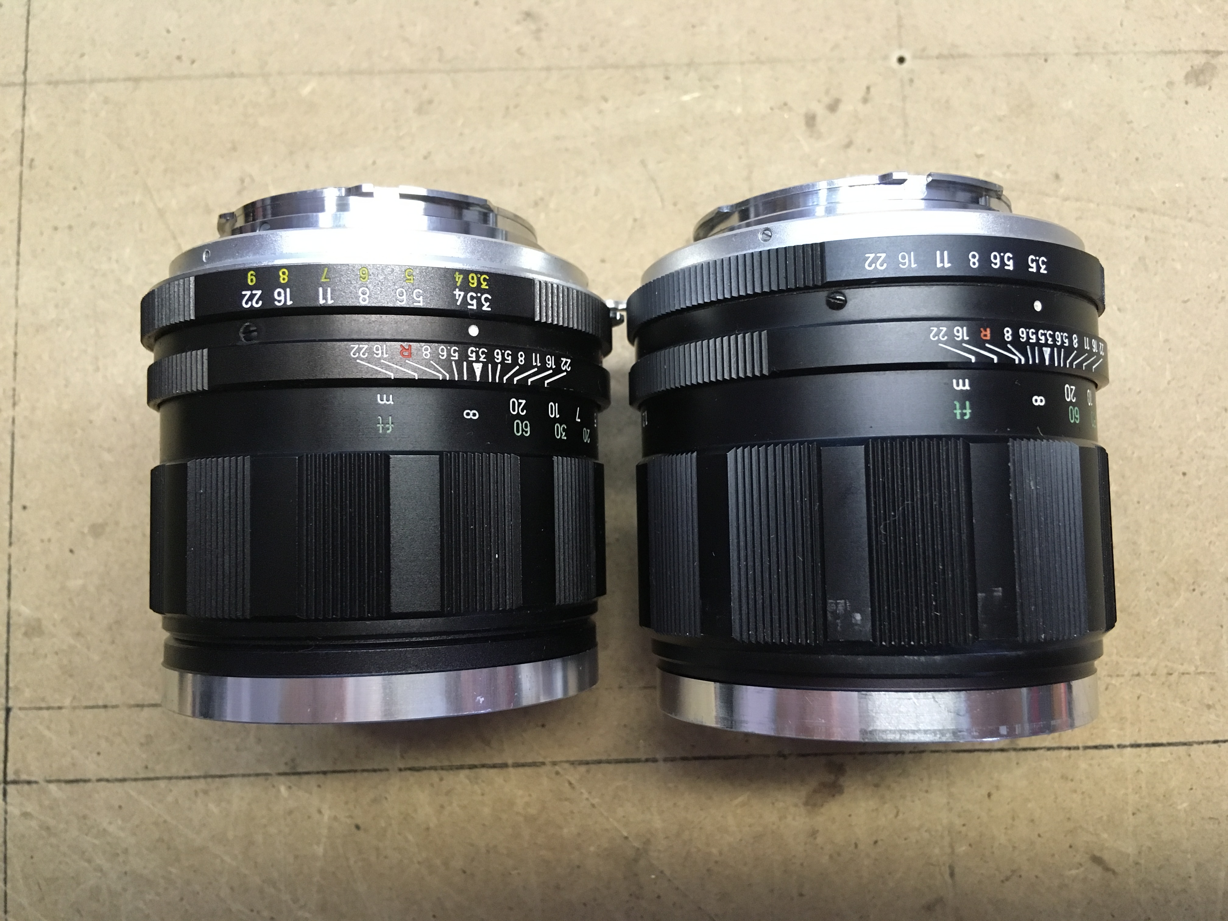
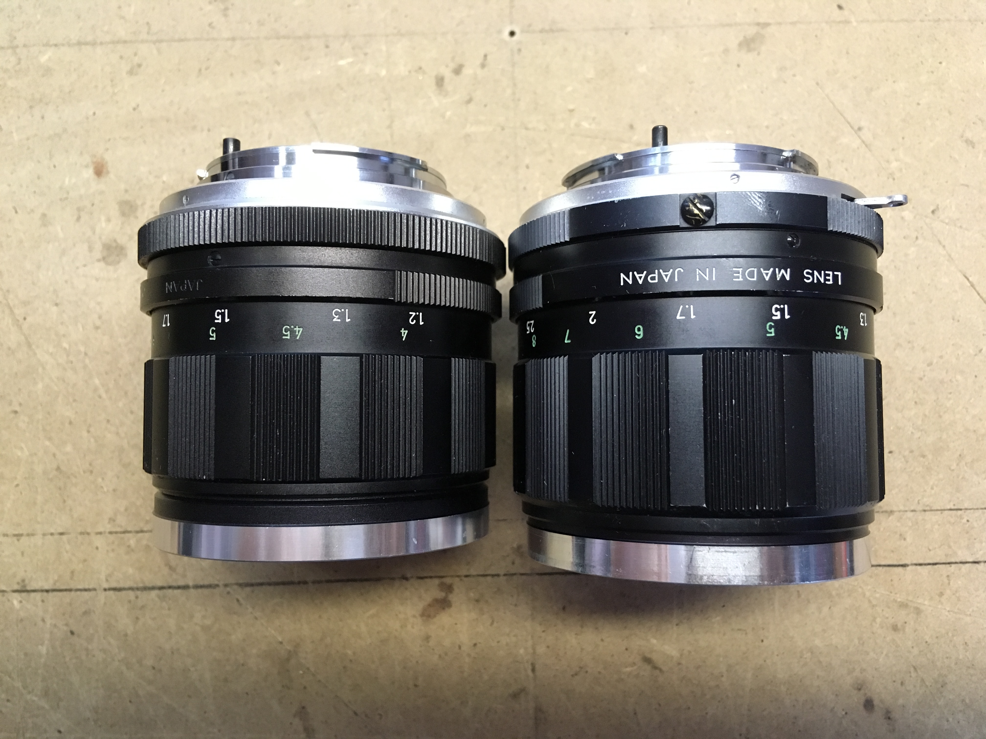
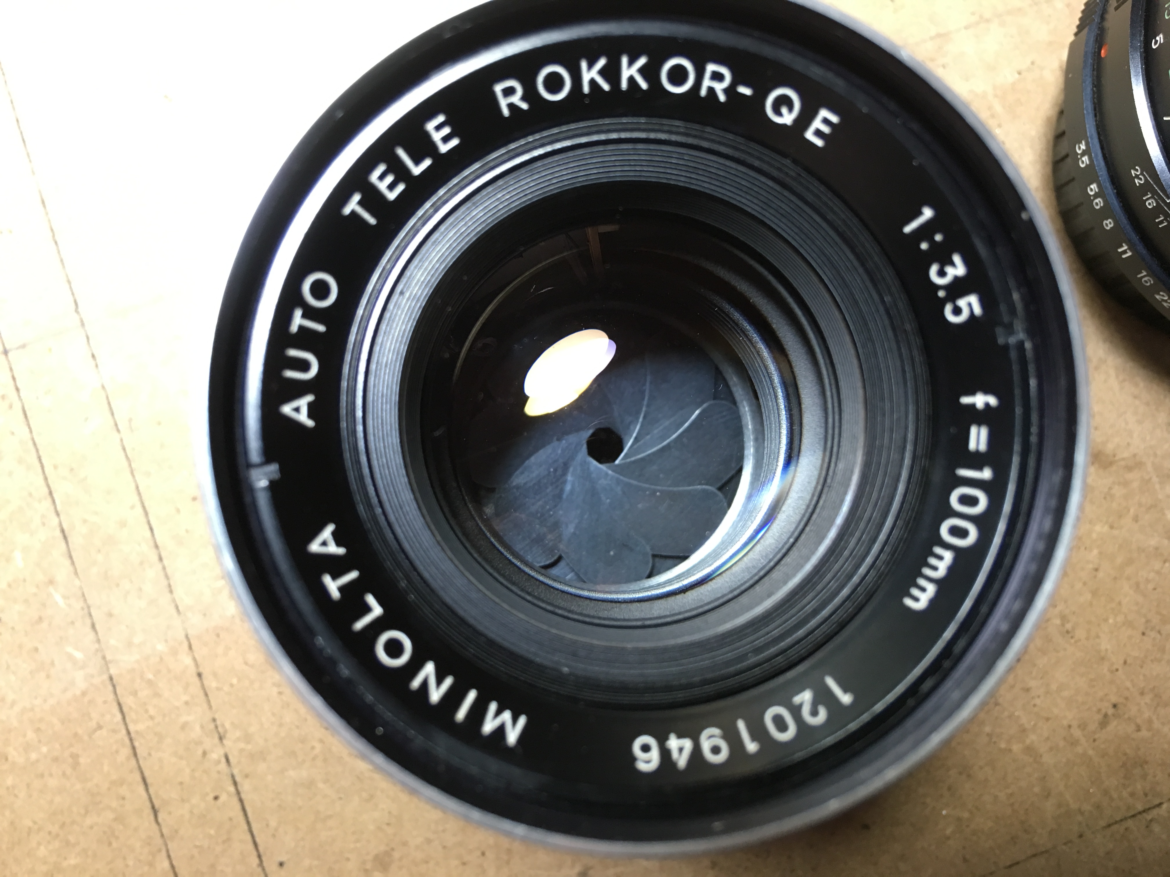
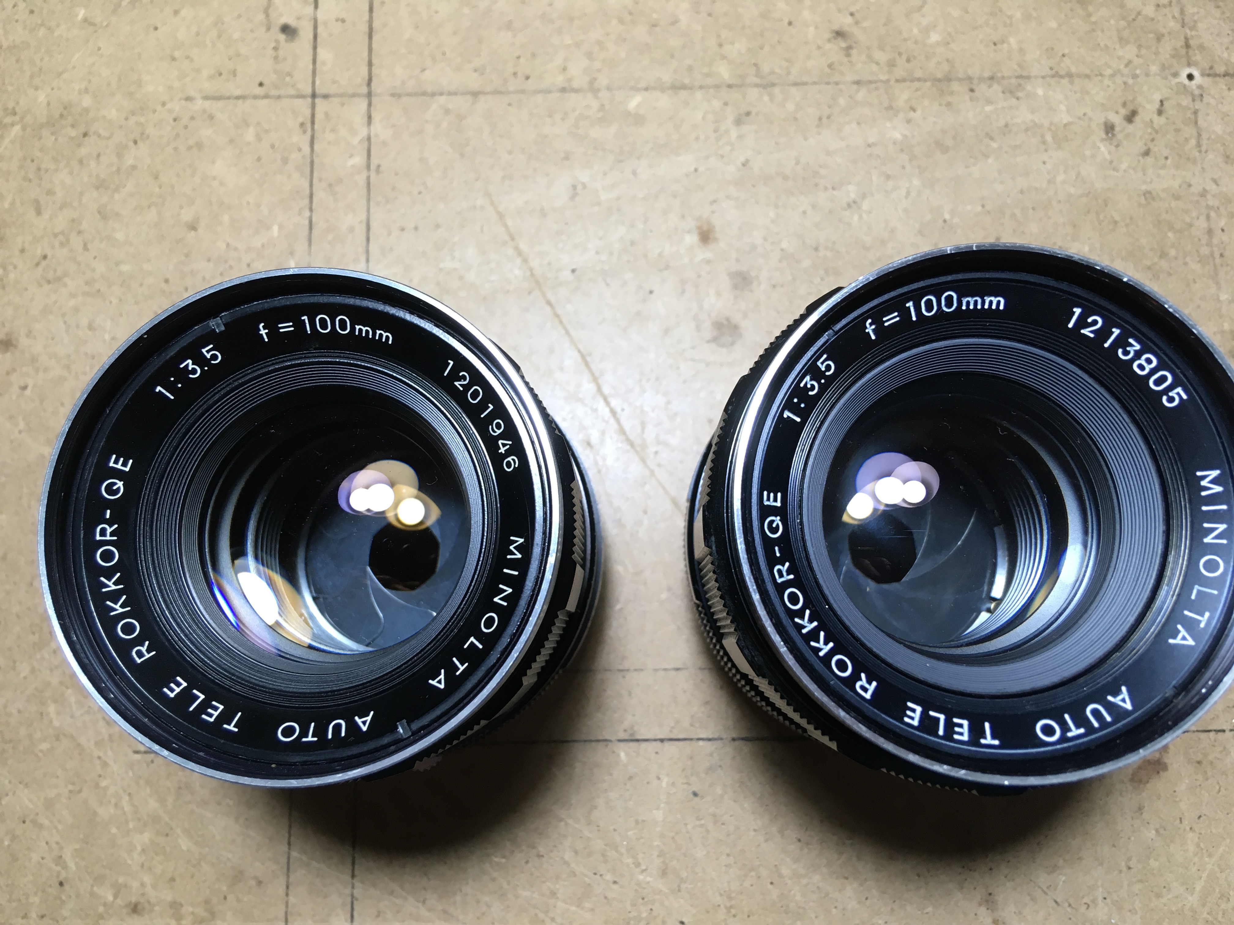
 This is one of the rarest lenses that I have had the pleasure to work on: a 1958 Minolta Auto Tele Rokkor with yellow LV engravings, apparently less than 2,000 ever made, to coincide with the release of the new SR2, Minolta’s first SLR in a long line, with loads of new features. I digress. The lens is a 7-lens construction and actually very good even by today’s standards. Not as clinically sharp as the much later 5- and 4-lensers, but still very nice.
This one is outside very pretty, the problem with it is that the iris had oil on it, making it rather sluggish. Not SO much of a problem, but definitely needed looking at to use it regularly.
Actually quite easy to dismantle (I never had one of these in my hands yet!) and the solution to the problem, largely due to the iris assembly being in the centre of the lens, was also simple enough.
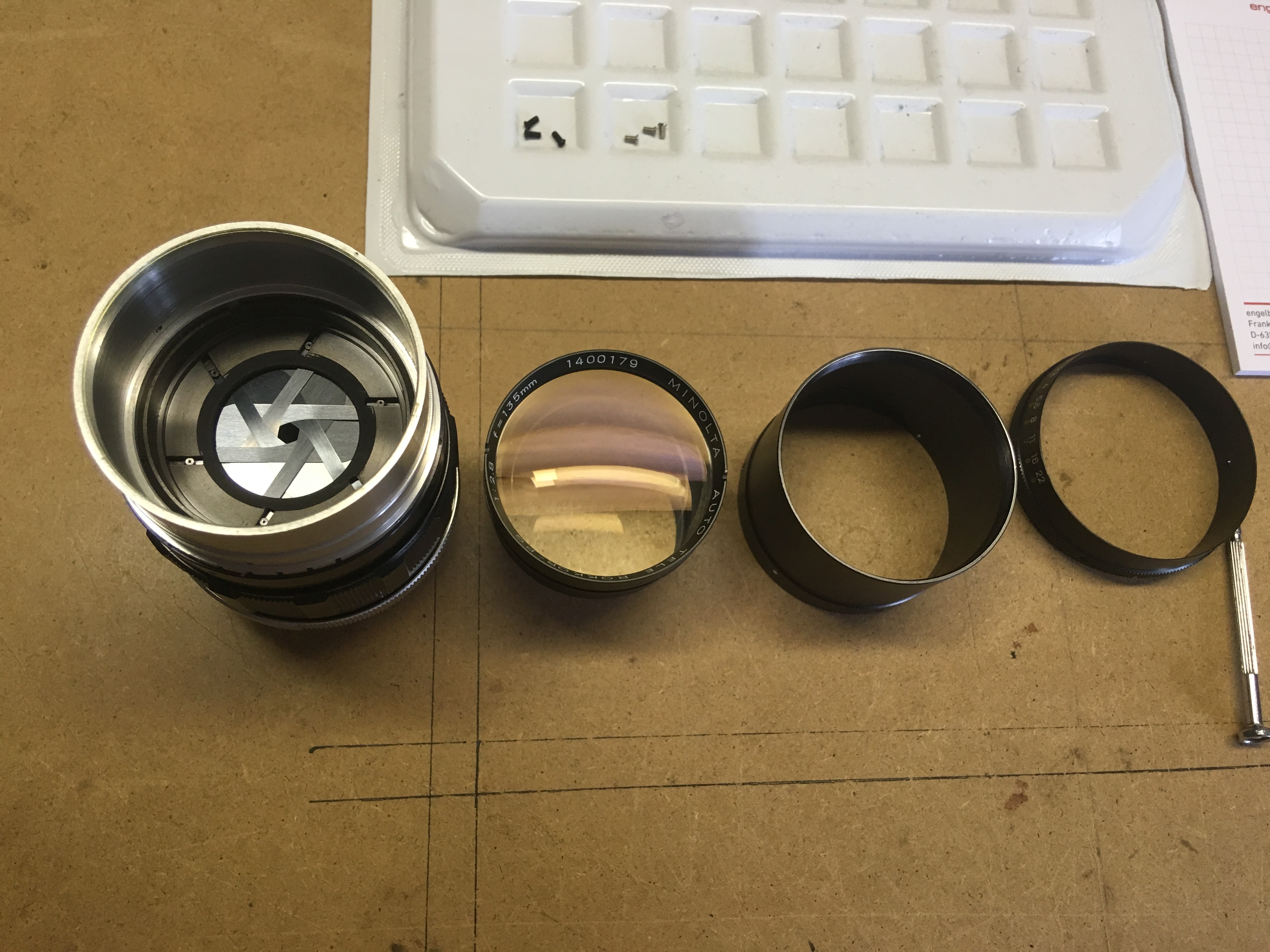
There are a few things that can be done incorrectly regarding the order of dismantling – guess how I know – so it would be wise to stick to the order given as follows:
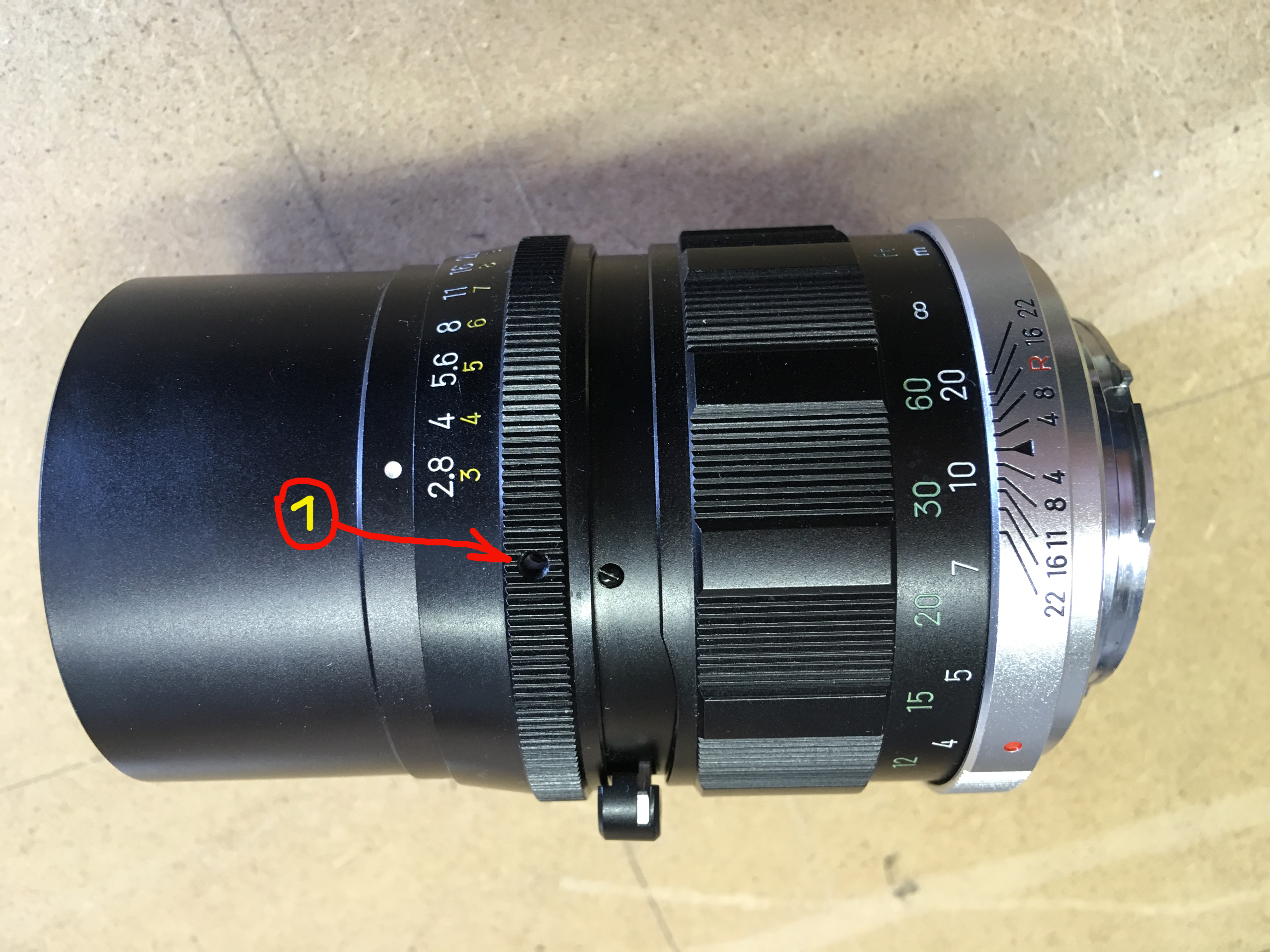
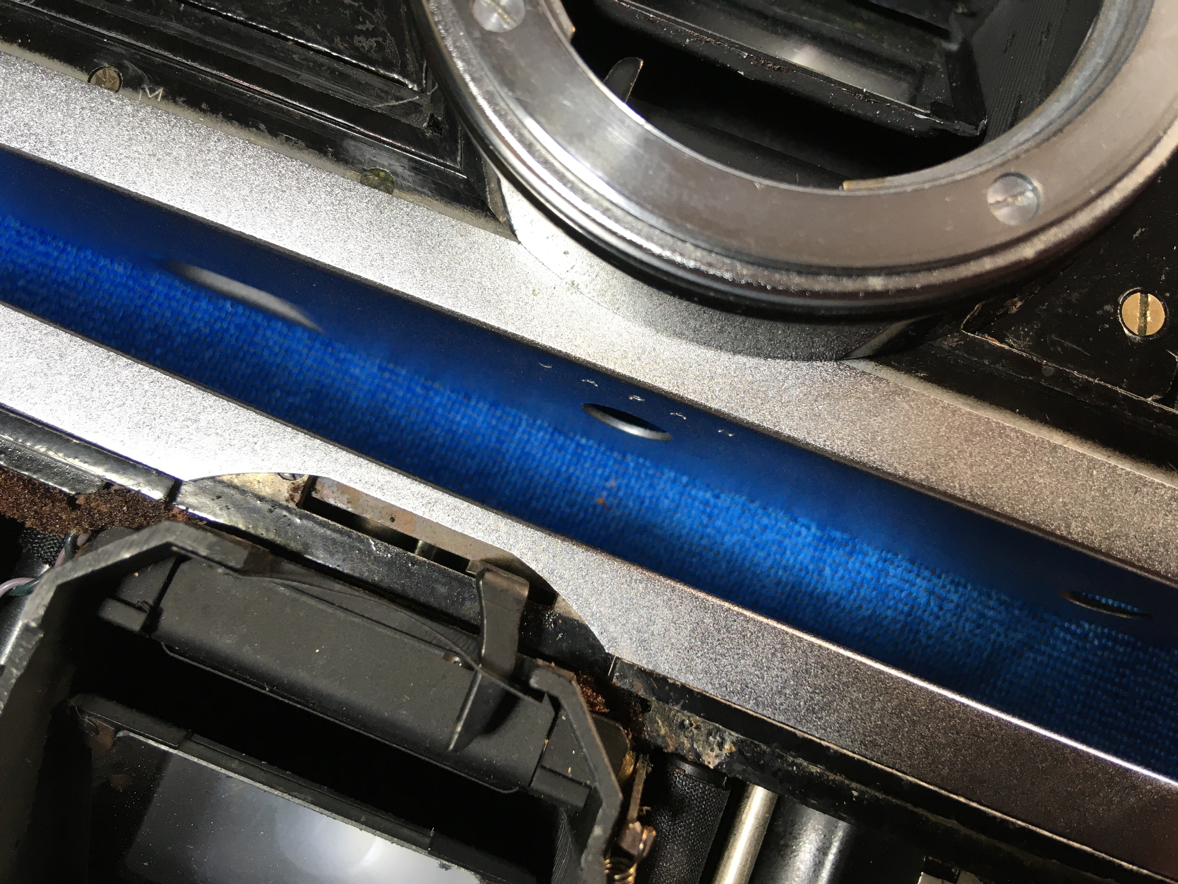
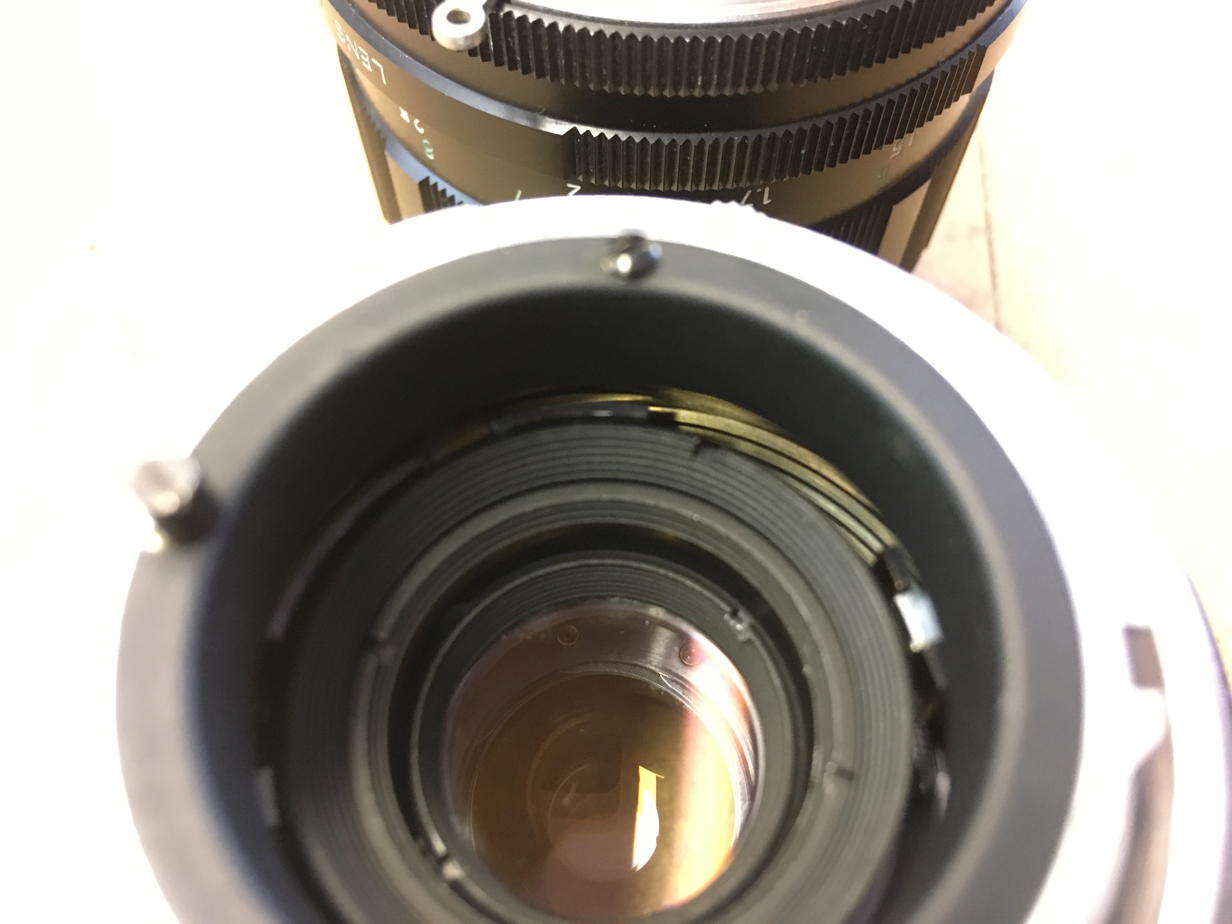
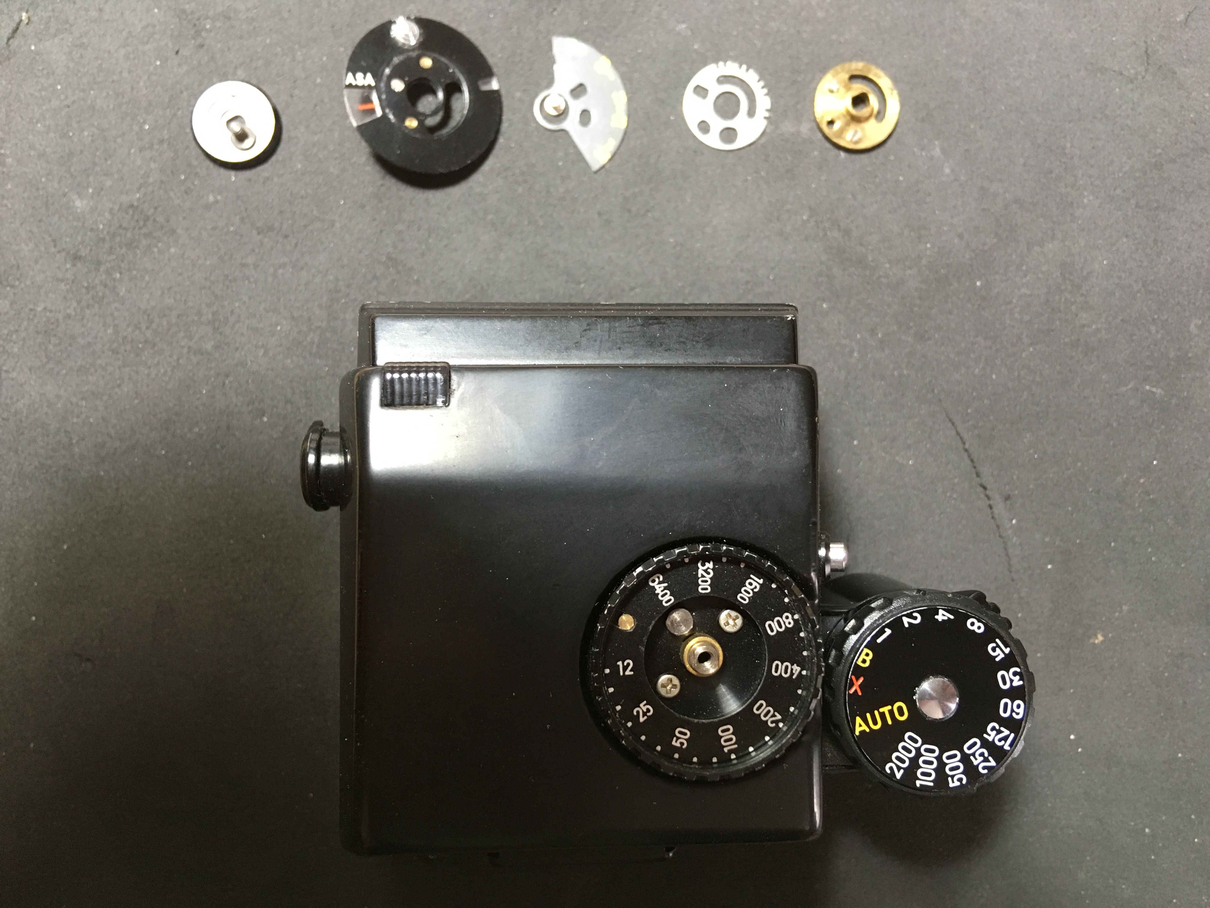
1: Undo the three black screws round the aperture ring. The one at this spot is the longest and belongs back here on reassembly. Inside the ring there are tiny balls that detent into the slots on the barrel (as can be seen on the picture) to give those snappy click-stops and to smooth the turning of the ring. Don’t lose them! A spot of grease will hold them on place for reassembly.
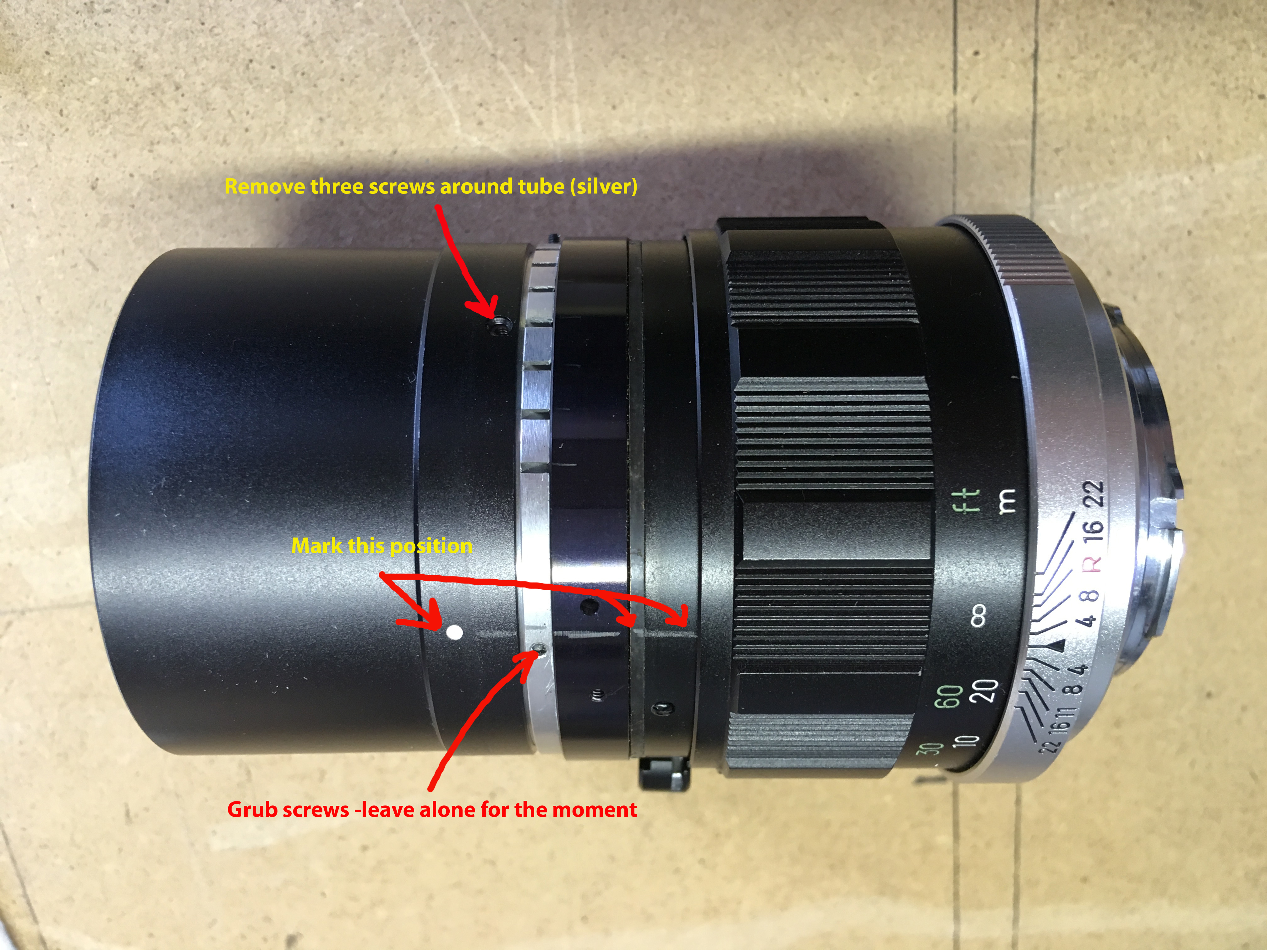
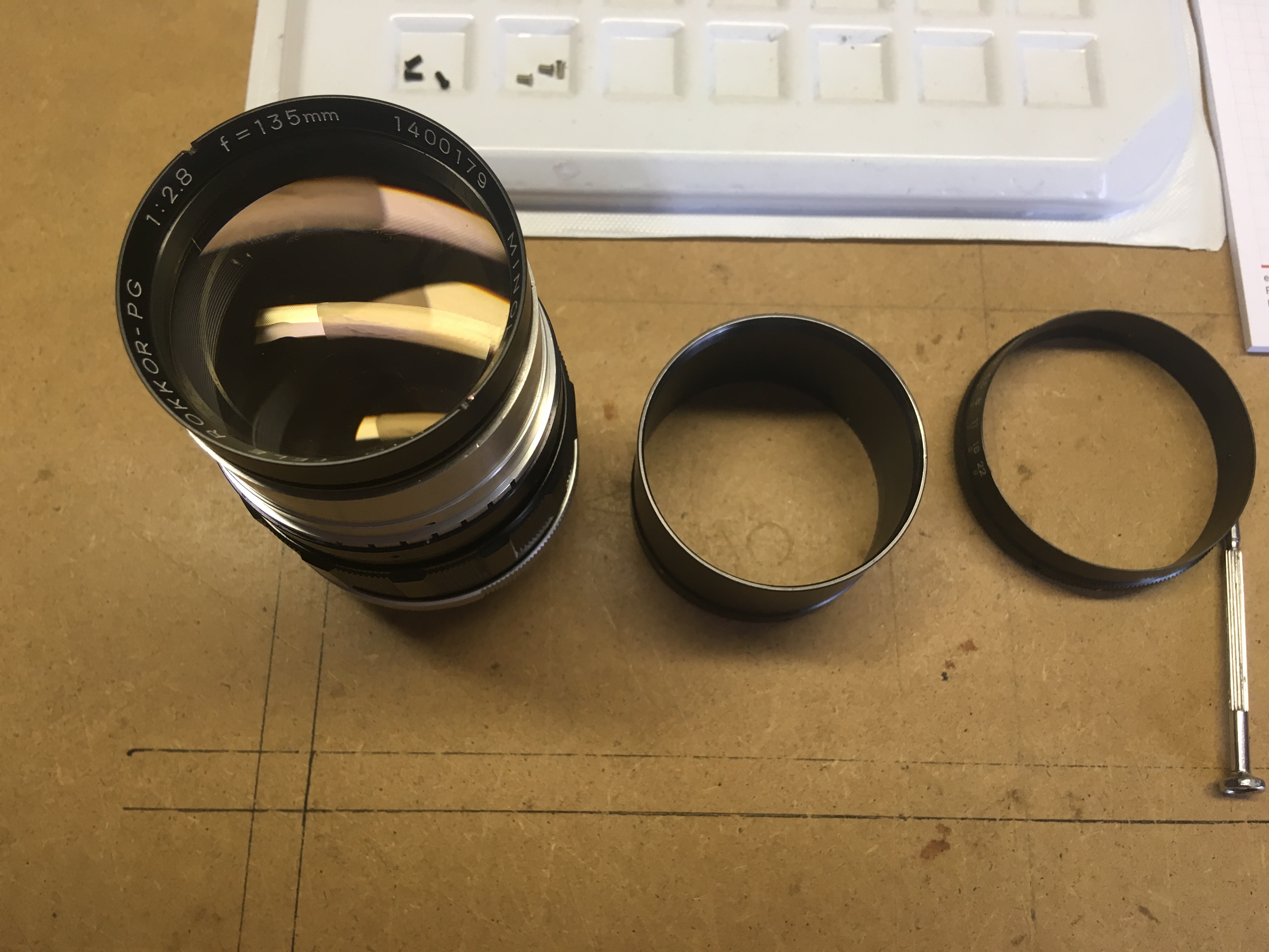
2) Remove the three silver screws around the barrel, which then can be easily pulled off the front.
3) The front lens element needs to be taken off next to access the blades. Do this CAREFULLY and with the PROPER TOOL, otherwise you risk scratching or damaging the ring, or MUCH WORSE, the lens, which if it is in good nick, will be almost impossible to replace in a hurry. If you have undone the grub screws by accident due to impatience or curiosity, you will now reap the reward by having a pile of separate (thankfully only six) aperture blades rattling around the inside! Oh Joy! Never mind. The construction is so simple and needs no explaining here, apart from to mention that a steady hand and a pair of nice pointy tweezers do come in handy 🙂
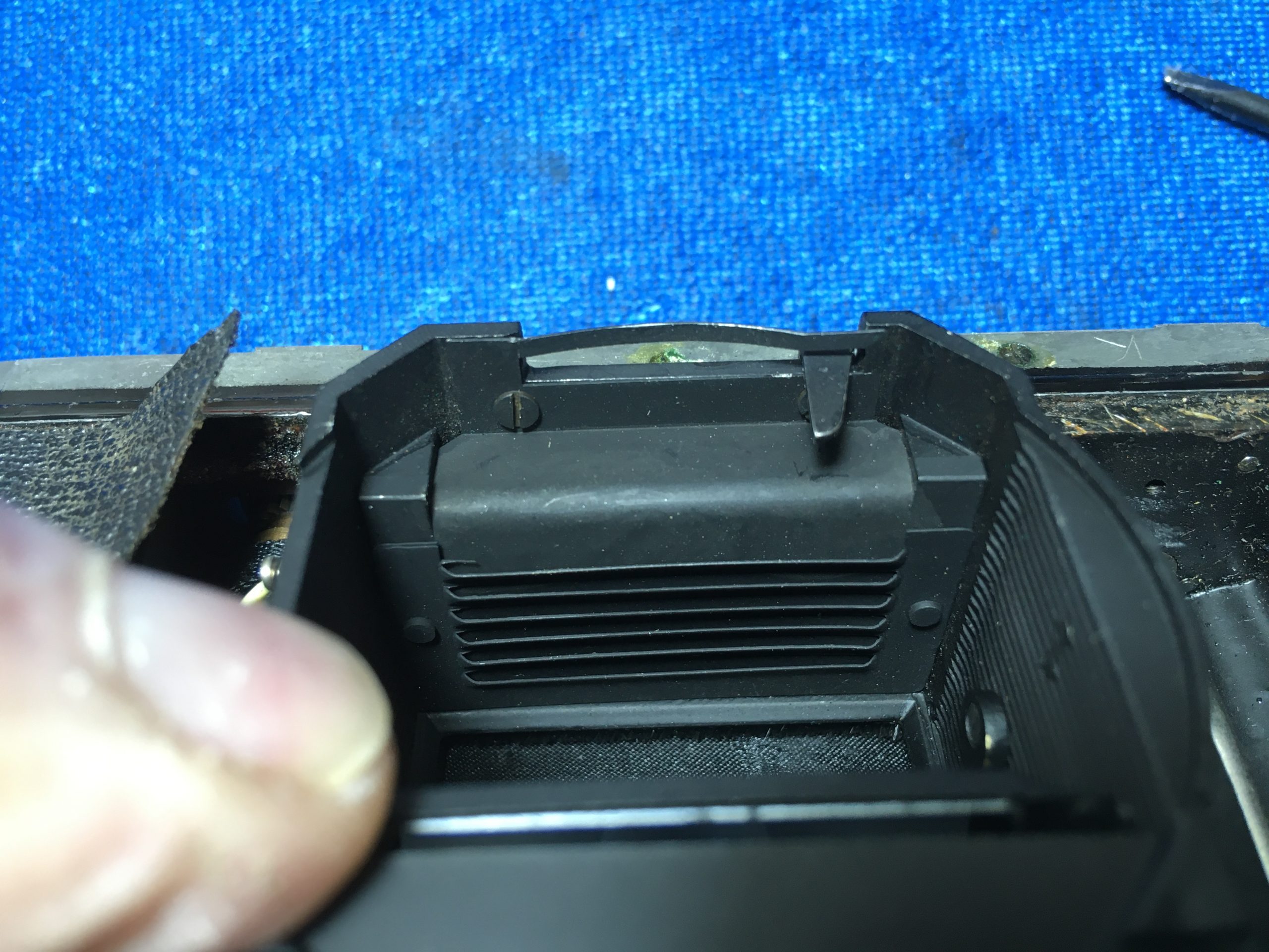
At this stage, you should be able to see the blades and what condition they are in. If they are only oily, then no further dismantling is necessary and they can simply be washed with a paintbrush dipped in some Methylated spirits or lighter fuel. While doing so, you can wiggle the stop-down lever thingy, to make the blades move open and closed, so they get a good rinsing. Be careful not to use too much meths and splash the rear lens from the inside. If you did, then you need to disassemble a bit more from the back (see further down) and wipe the lens properly using a moist lint-free cloth.
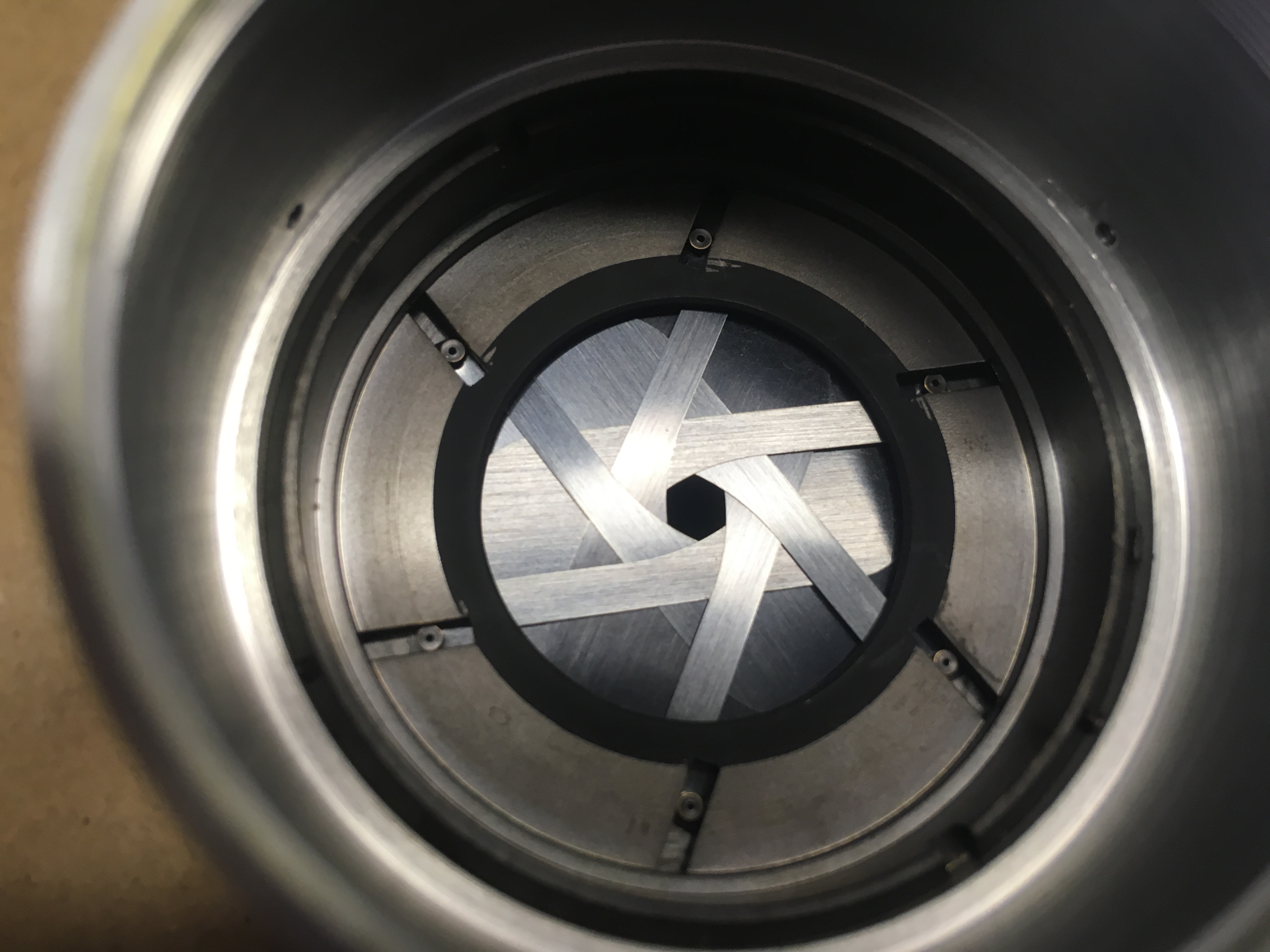
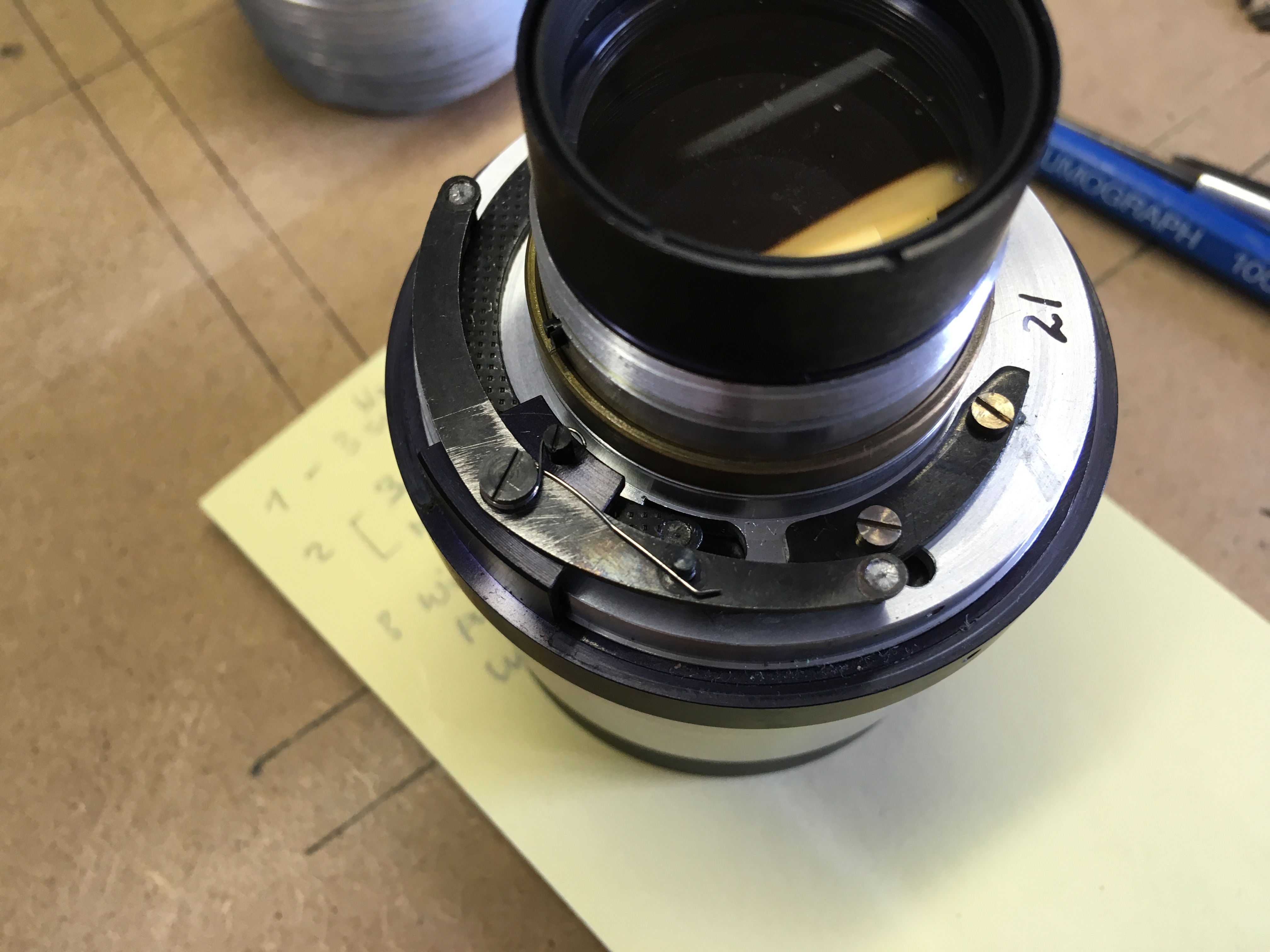
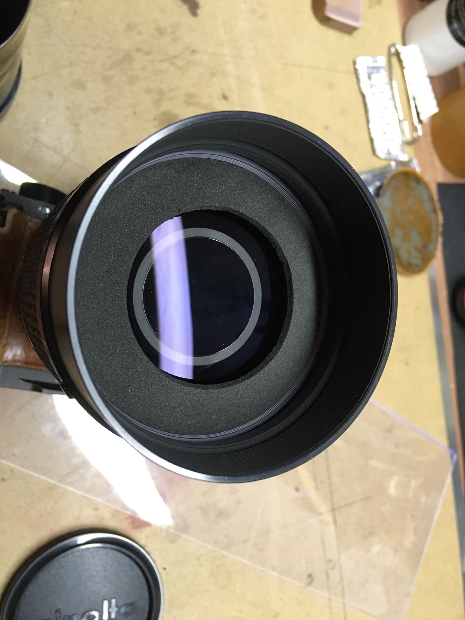
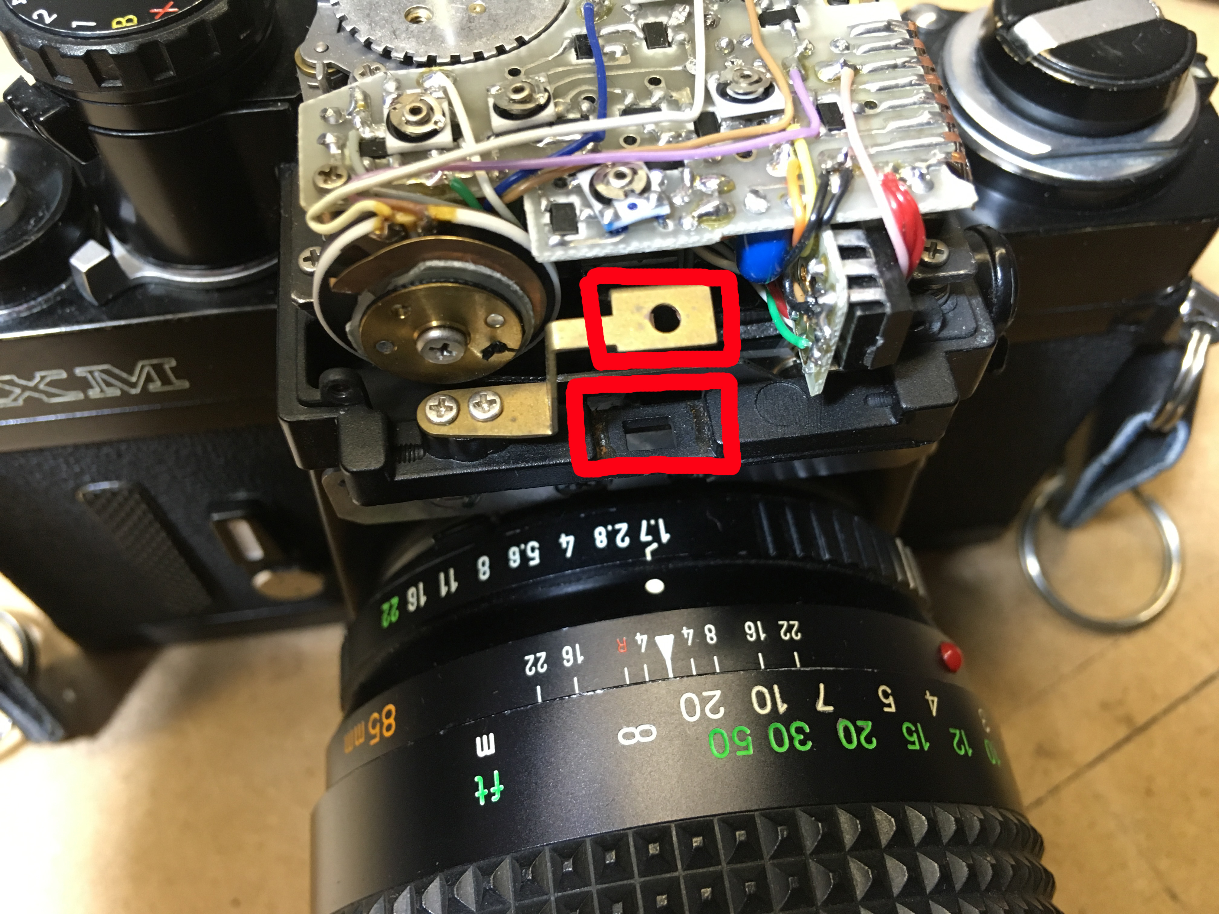
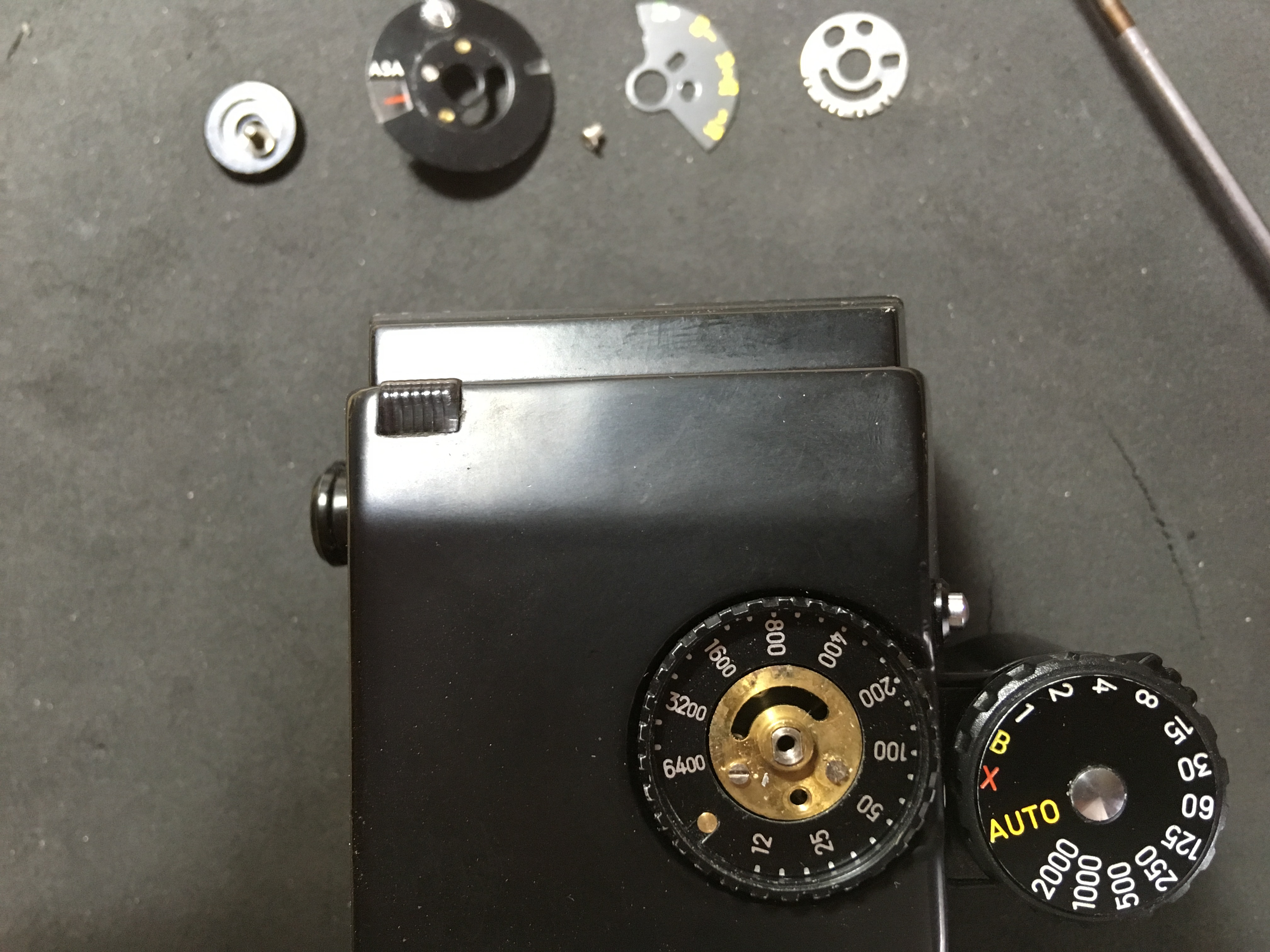
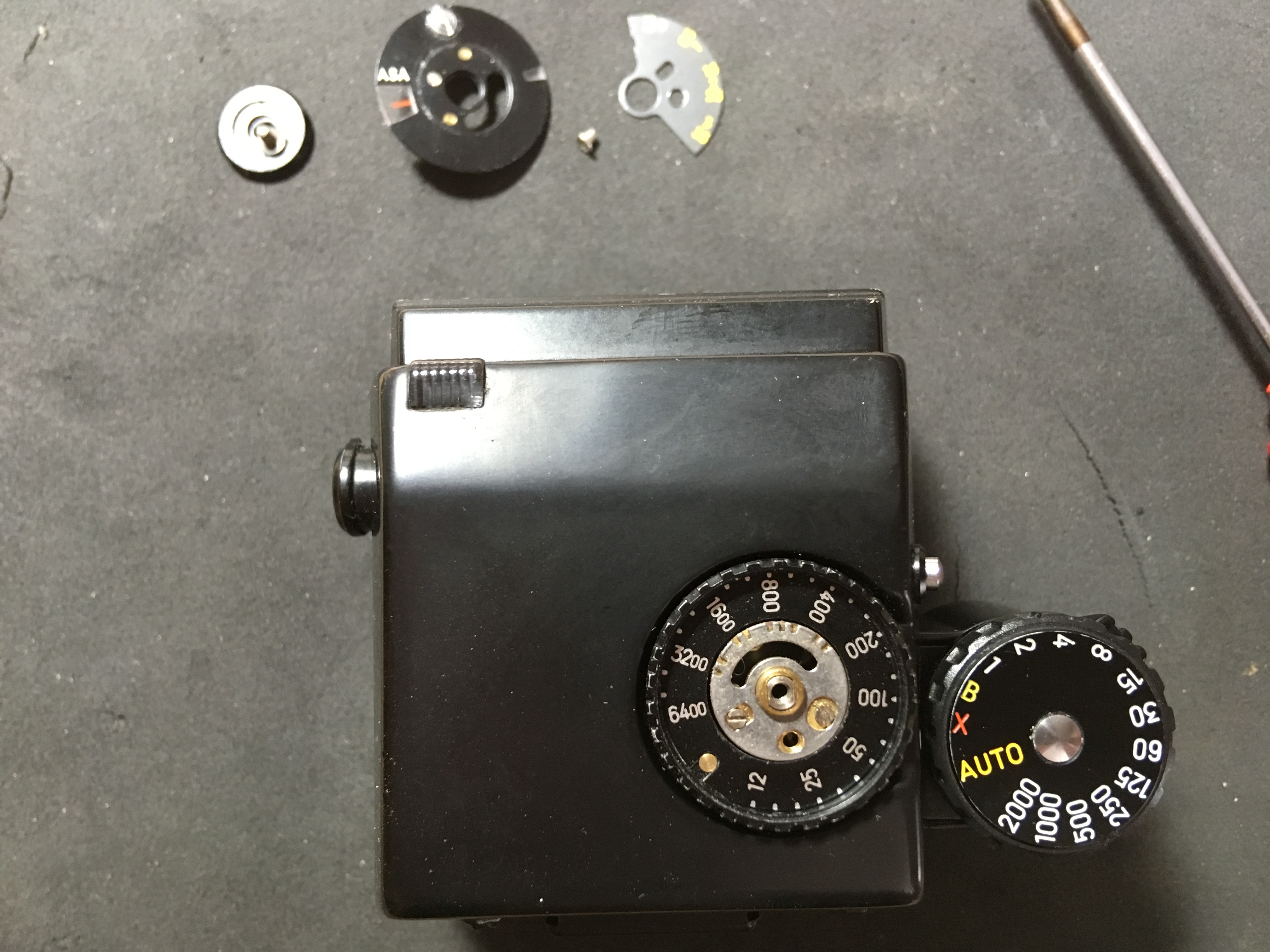
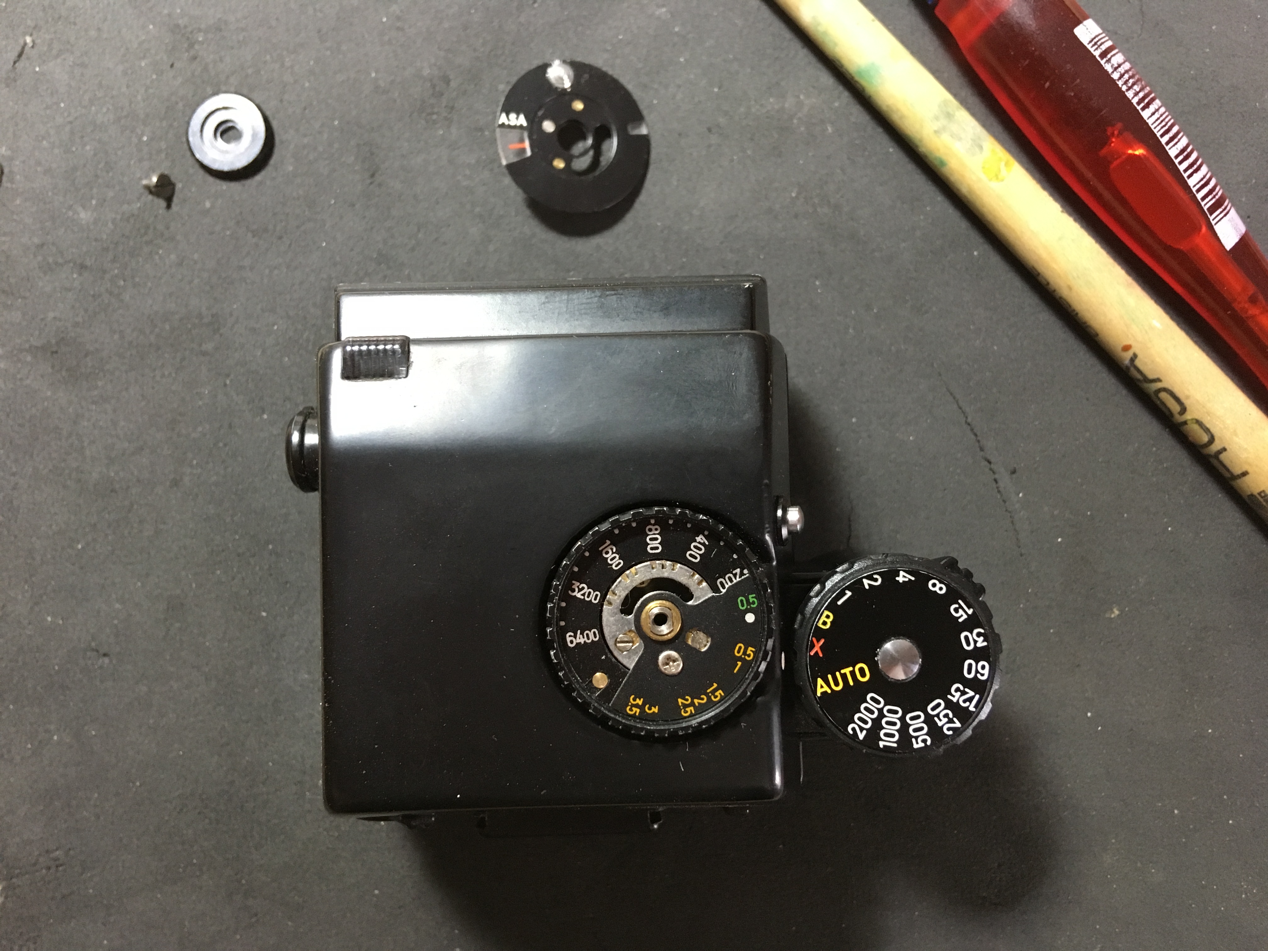
READ THIS FIRST BEFORE GOING ANY FURTHER: If you haven’t already done so, turn the whole assembly so that you are looking down the front at the blades. NOW, AFTER you have marked the position of the outside ring in the barrel, you can at last undo the grub screws and take out the inner ring holding the blades in. When you undo the grub screws, the outside ring could rotate, so mark it BEFORE you undo even one screw. The position of the outside of the ring is critical to the iris opening and therefore the exposure, so please don’t forget this. Dead centre in this picture, you can see the little silver ball that detents the aperture ring – lose it at your peril!
Now you can remove the parts carefully with preferably copper tweezers (make your own!) and clean and inspect properly, prior to reassembly – with cotton gloves on, please: fingerprints on the blades are so unprofessional!
OK, so yours, like mine were not only oily, but one was a bit bent? I can only assume that someone else with good intentions tried to fix it years ago and oiled them for good measure, but was not very light handed with reassembly. It’s always only ONE blade that gets bent, the last one, since it has to be tucked under rest that are already in place – a bit like Escher’s endless staircase! You know how to do it, if you have ever closed a cardboard box by overlapping the ears on the lid: Same principle, if a bit smaller. It will be obvious when you get that far. Not much is needed to make the blades ‘sluggish’ due to the added friction and no amount of oil helps (it in fact makes it worse, as we now know).
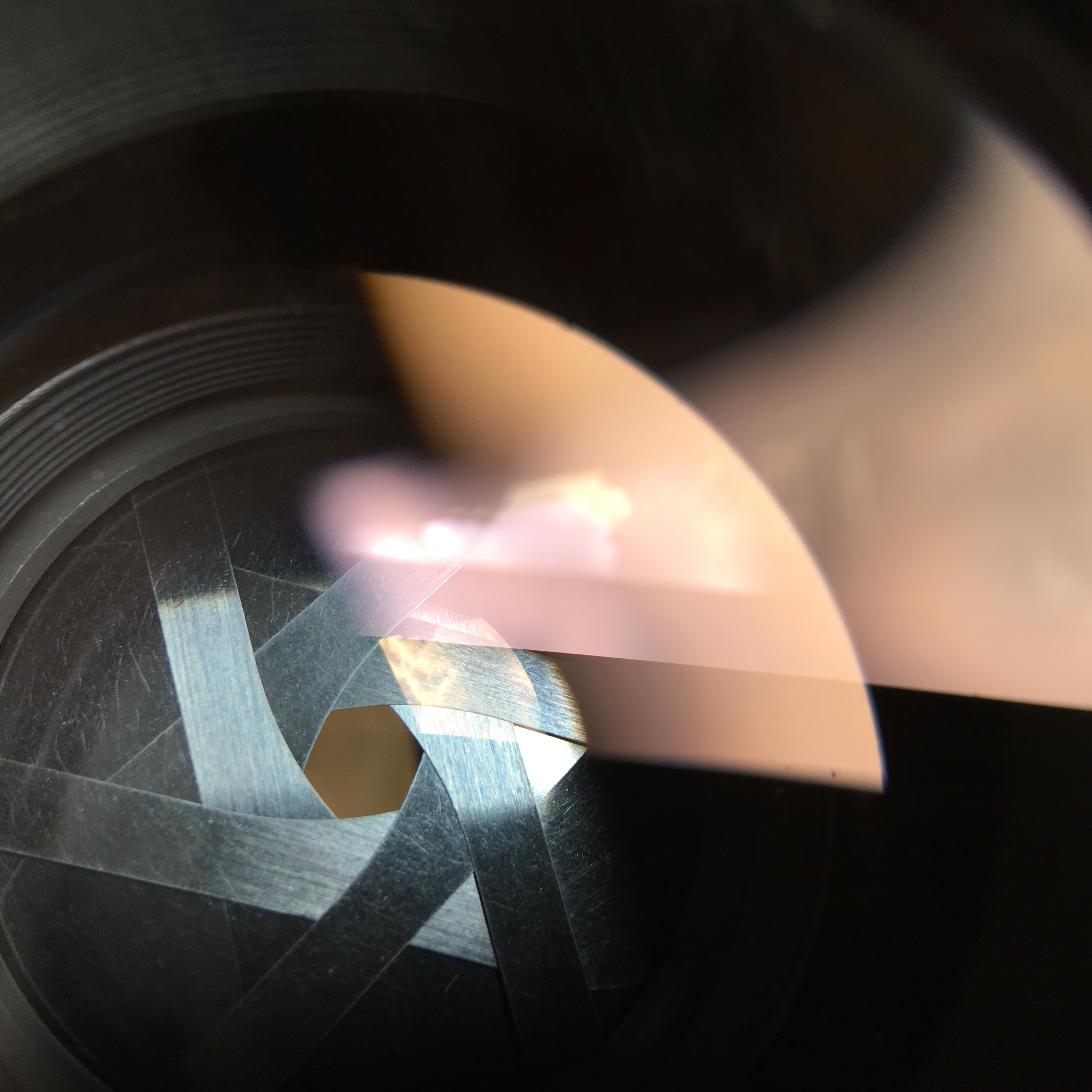
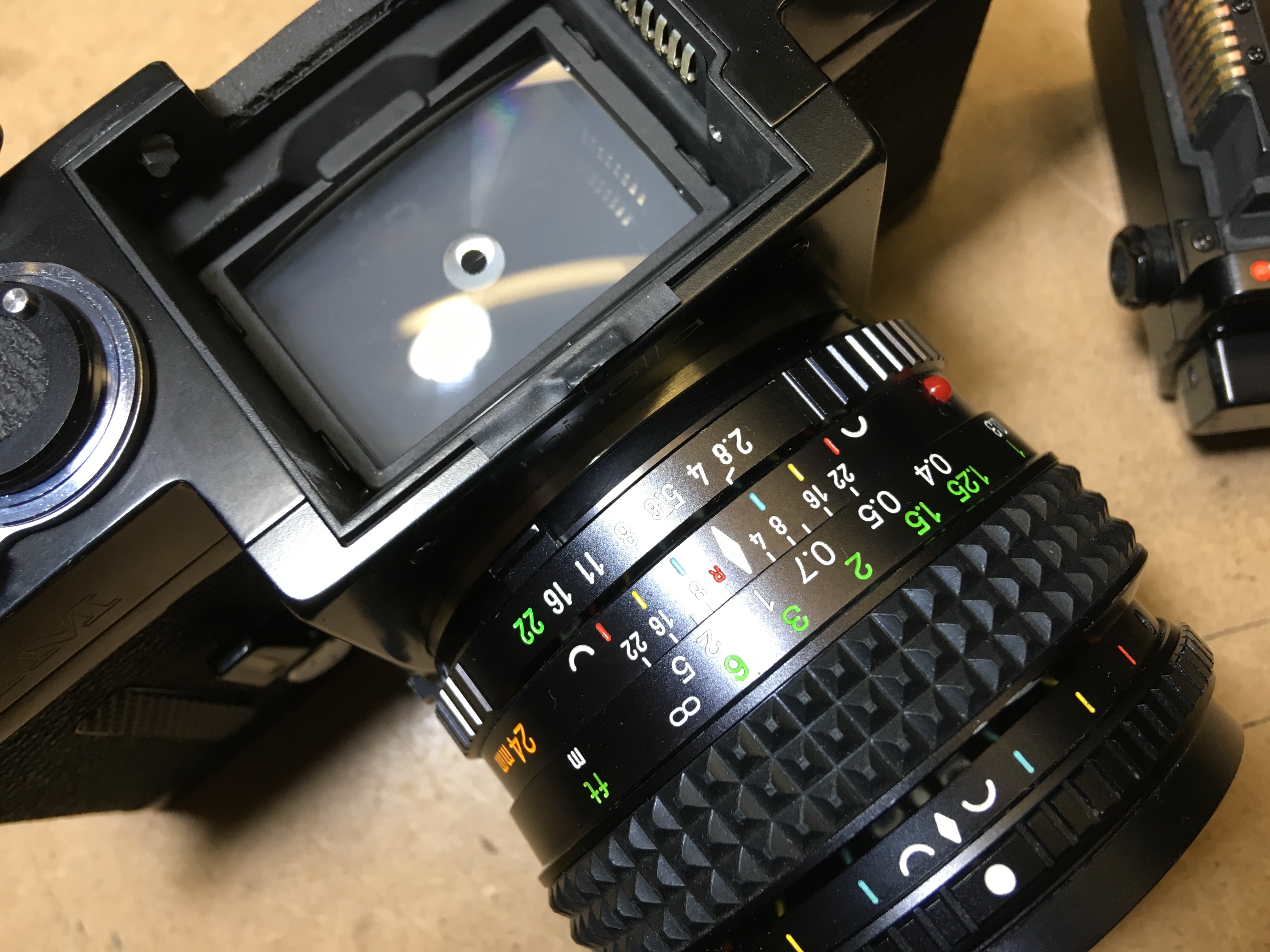
This is what they look like when reassembled through the replaced front lens. Reassembly is simply the reverse of the dismantling job, not forgetting to place the long screw where it belongs. In this picture, you can just see the nick on the top screw slot on the lens-ring, where I slipped despite having the correct tool – the lens was VERY tight. I suspect that it was secured with Loctite or similar.
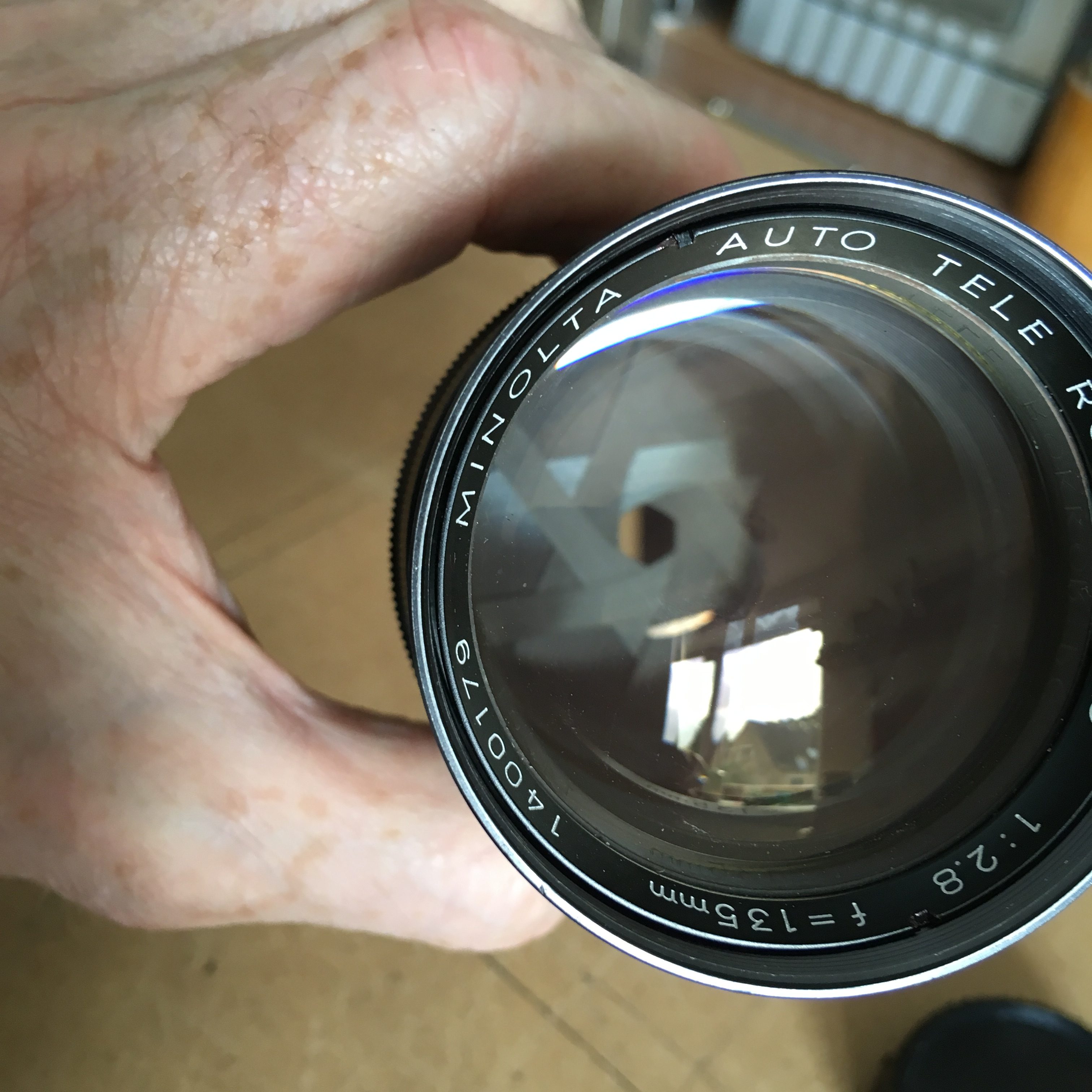
Here a bit closer, in focus and nice and clean!
So, just because we are curious and maybe because we spilled meths on the rear element, or to get at the mechanism and to be able to not only disassemble but also adjust, the rear end has to be taken off. There is actually no reason to NEED to disassemble further, as everything for the aperture blades can be accessed from the front, but since we got this far, here goes:
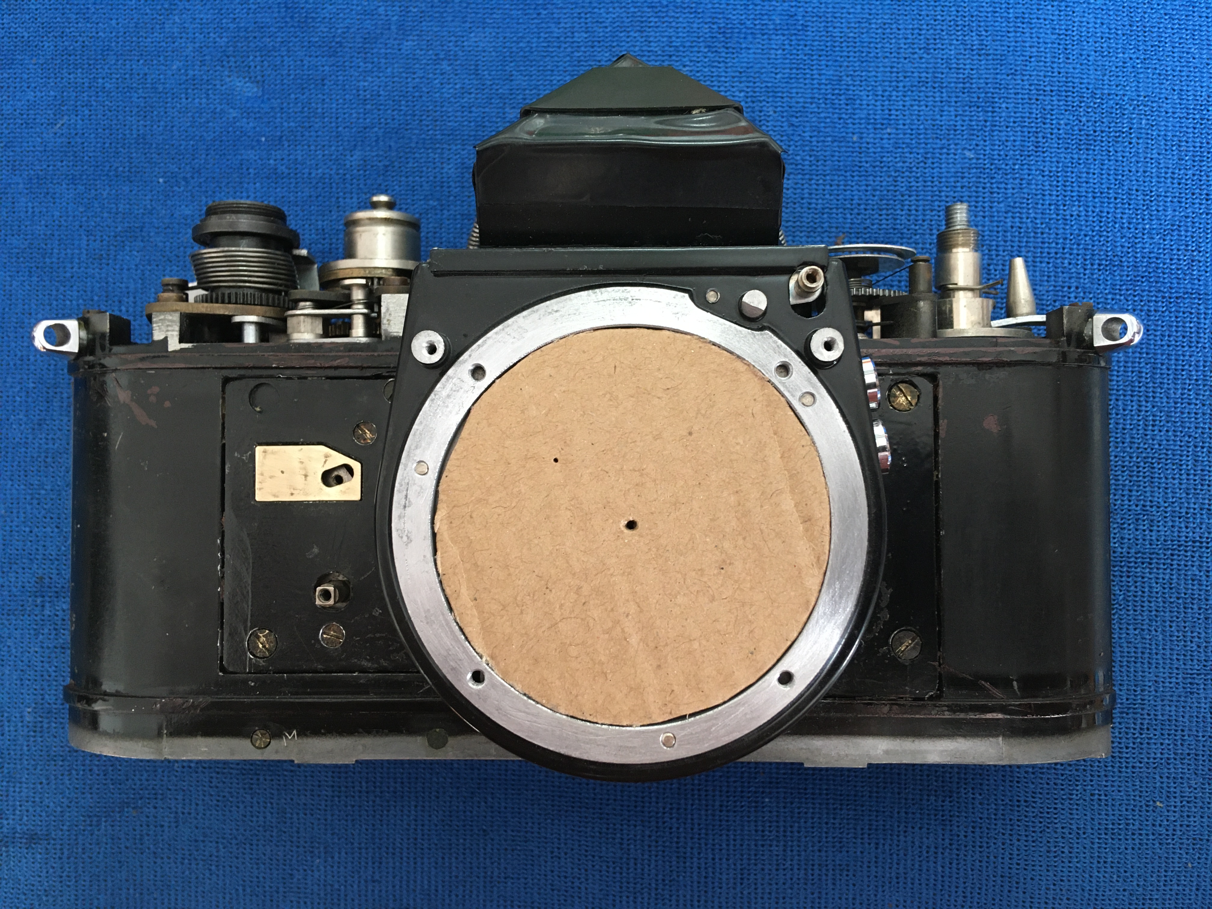
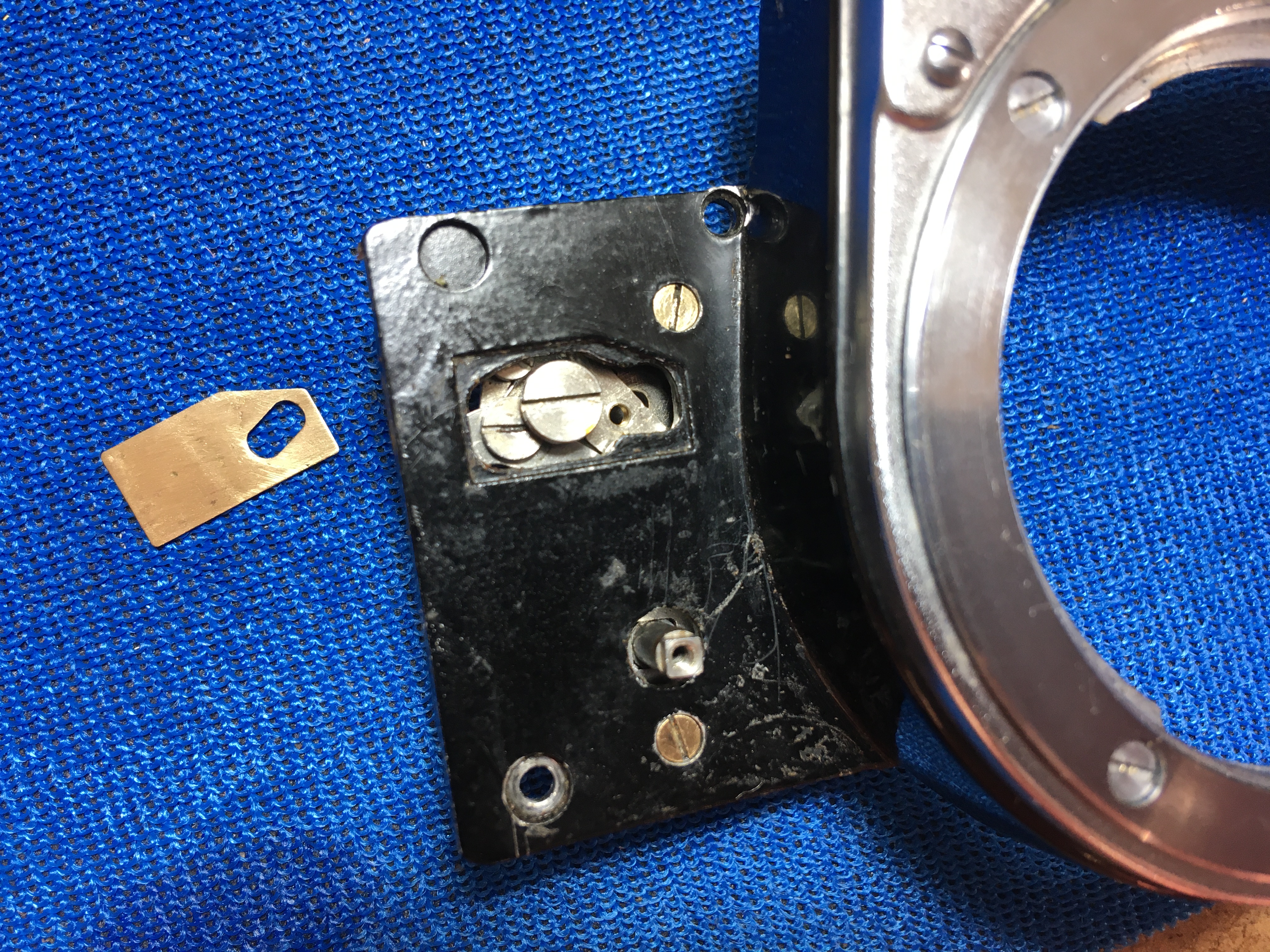
4) Remove the rear mount (4 screws)
5) Unscrew the tube and rectangular hole (!) around the rear lens and put them out of harm’s way.
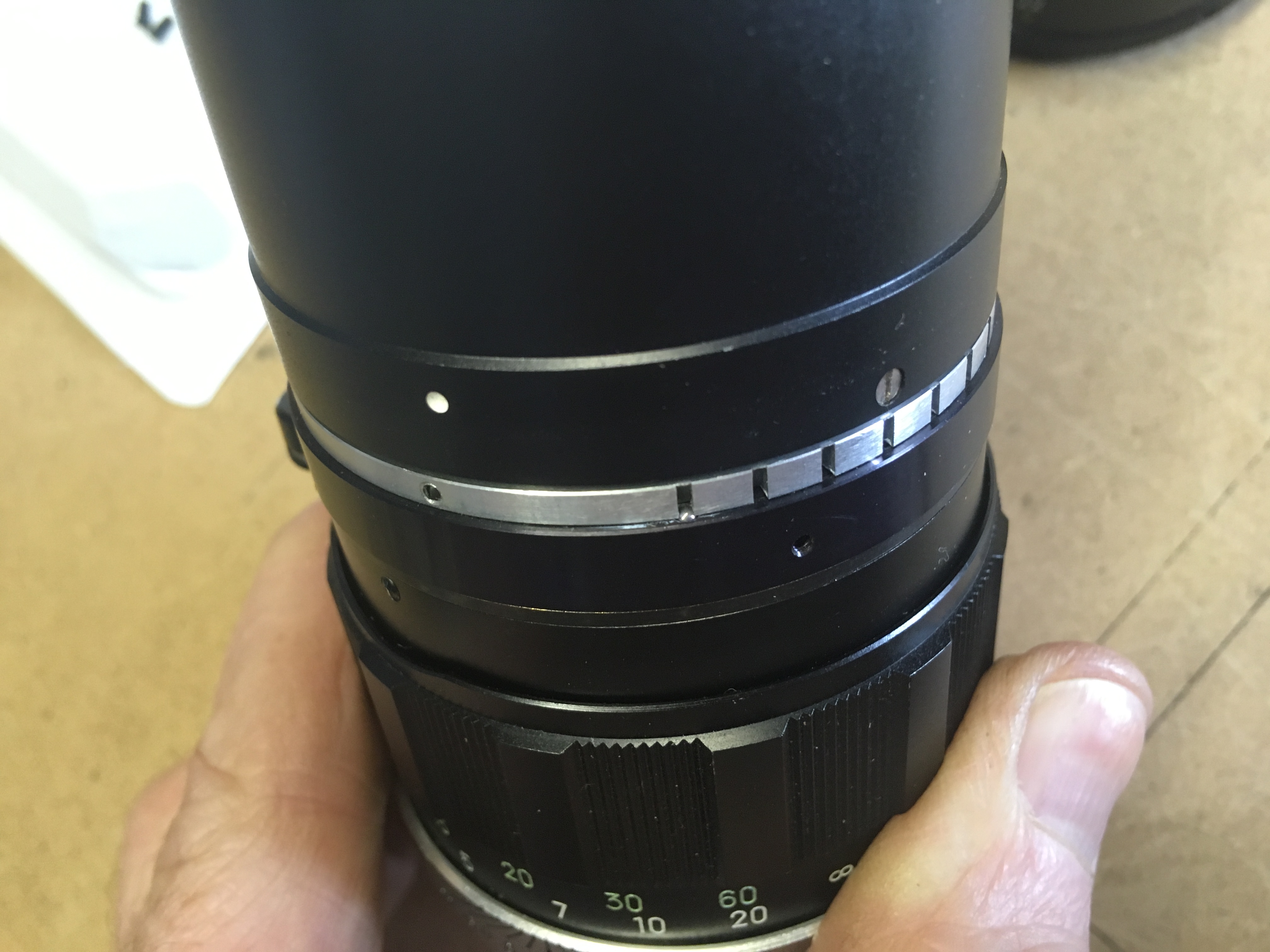
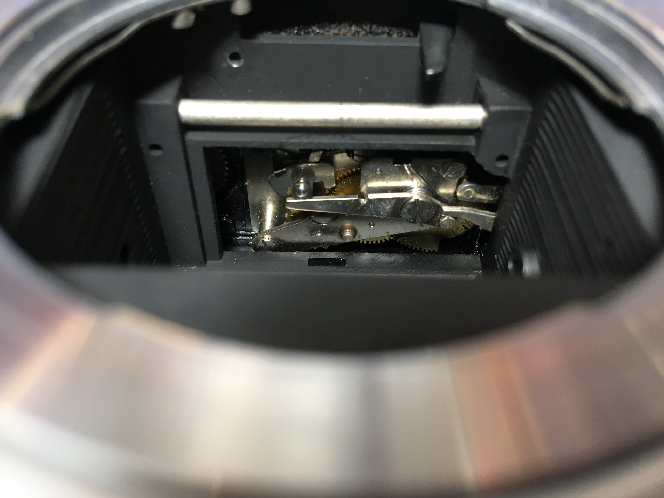
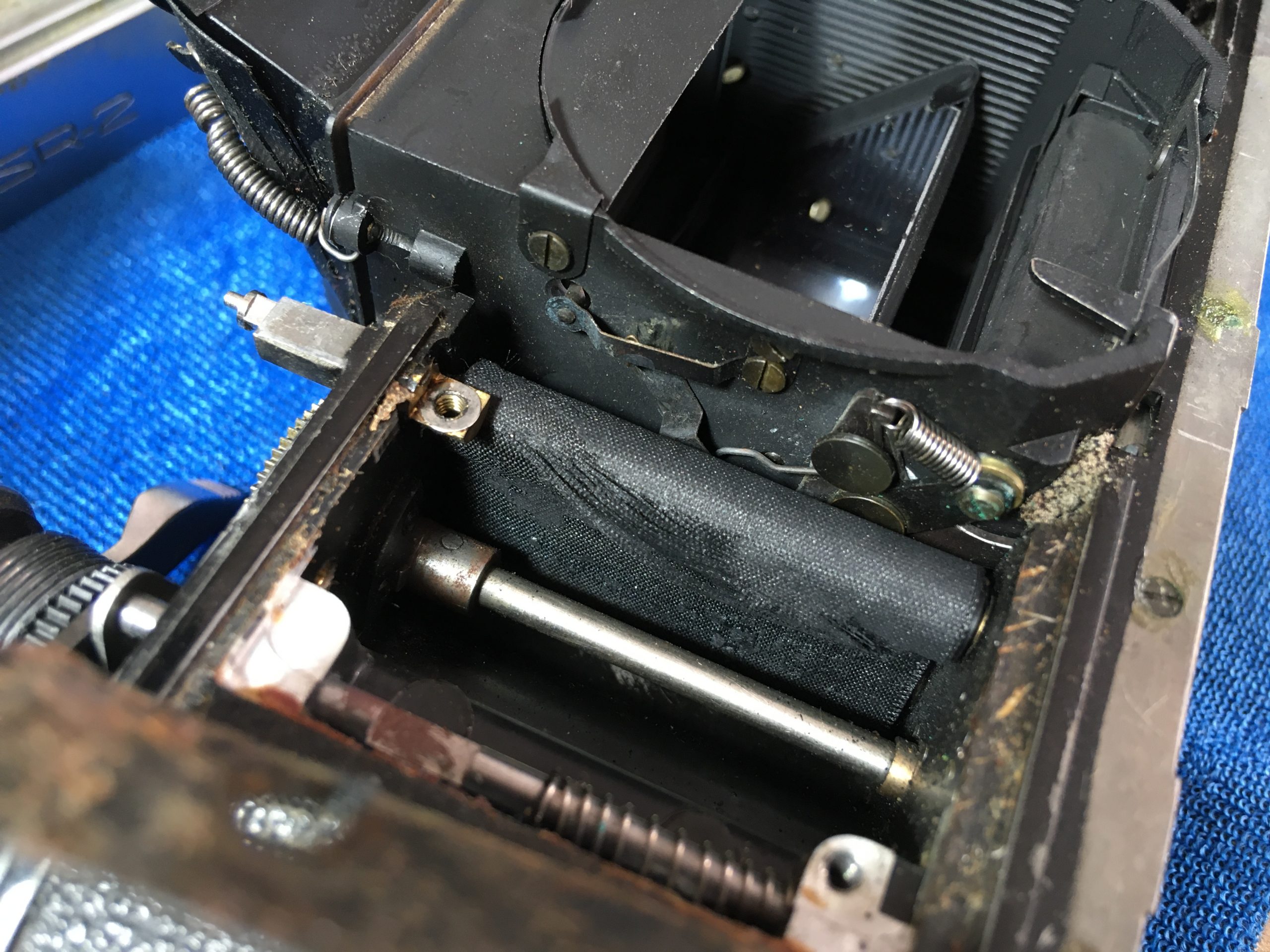
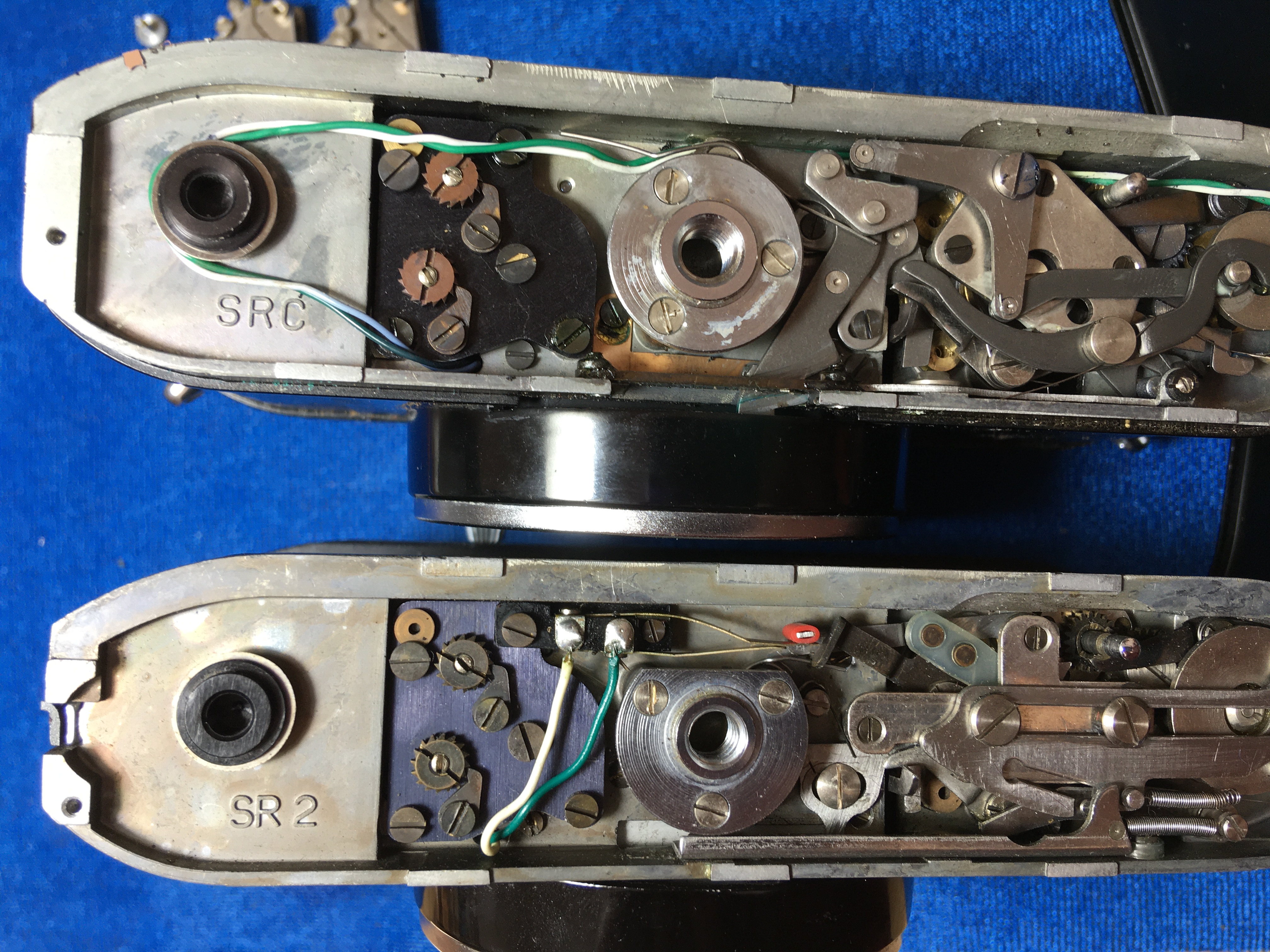
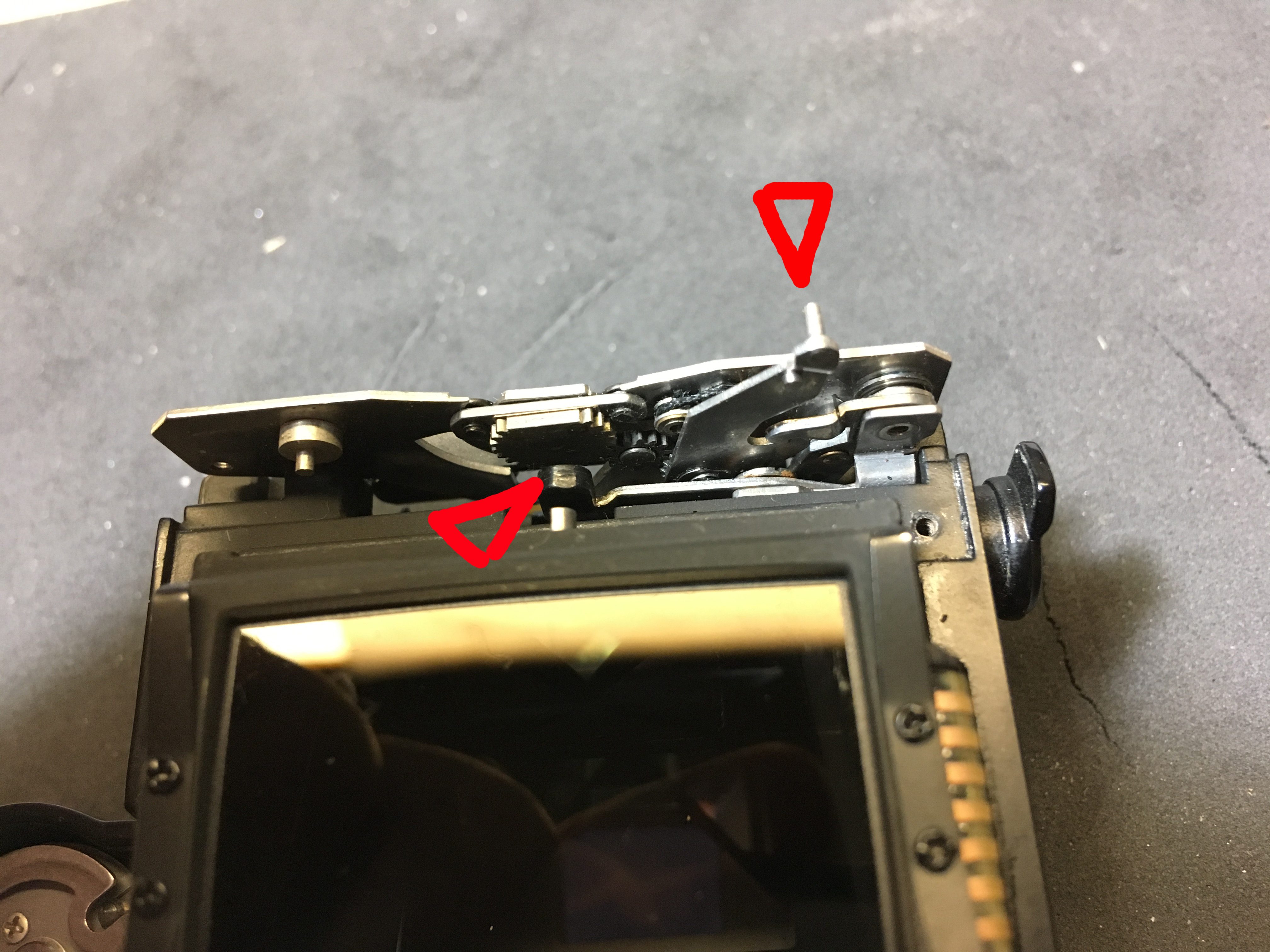
6) Now you can safely unwind the focus-ring and PLEASE note and mark the spot where it comes off the thread to realign it when reassembling. Time consuming if you forget and have to find the right spot by trial and error – there are lots of possible ways to start the thread (8, actually). Once off and with the simple barrel at the front removed (3 screws), this is what it looks like:
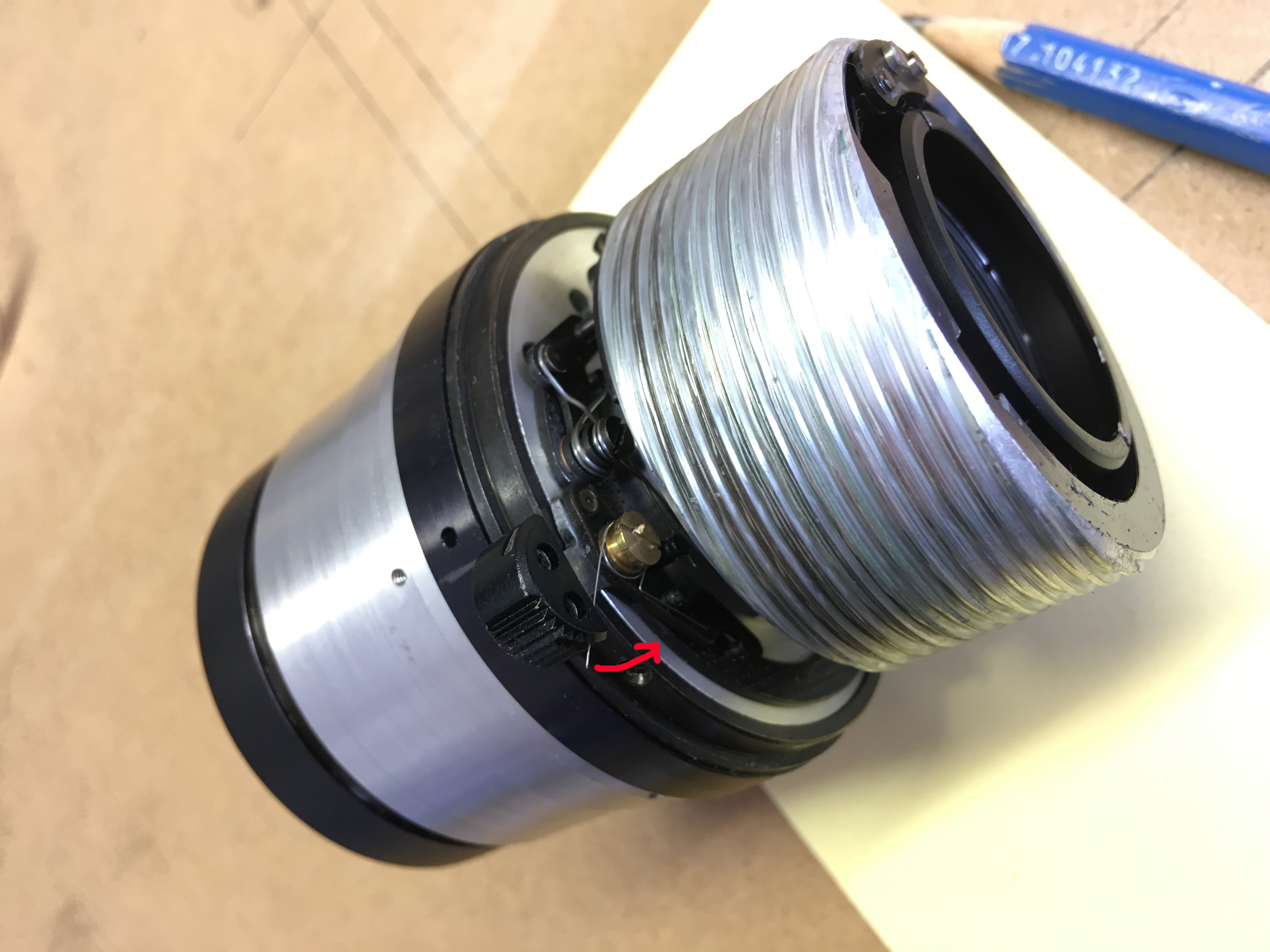
The red arrow shows where the end of the spring belongs when the rear end is reassembled – tucked INSIDE the front tube/barrel when replaced!
In the above picture, the stop-down-knob is around the back, hidden by the rear lens element in this shot, but this shows the arrangement of the spring on the lever which actually causes the iris to open and close. Its function will be obvious when you actually have it in your hand and actuate the stop-down. It also shows the rear element which can simply be unscrewed to clean.
Reassembly:
7) Put the blades back together carefully (especially the last one), arranging firstly the blades the only way that they fit – yes, there is only one way! – and then placing the front ring over them and aligning the pins on the blades in the slots/holes provided.
8) Line up the outer ring with the mark you made OR look for the bright-spots/ dents in the aluminium where the grub-screws originally were. You might have to turn the ring once or twice, since there are three possible positions 🙂 Replace the grub-screws and make sure that they pinch not too tight, but hold everything in place.
9) Now you can test the freedom of the blades by twiddling the stop-down-knob.
10) If all is OK, replace the front end complete with aperture-ring and lens as a reversal of the disassembly. If not, try again!
11) Fix the screw-thread for the focus in place and the front tube/barrel, not forgetting to tuck the little spring inside by the stop-down-thingy before securing the 3 screws.
12) Position the outer focus barrel to screw onto the inner thread in the right place to enable to focus full length without fouling the stop-down-lever (you marked the position, remember?). If not, it’s trial and error time, looking at the bottom of the thread-travel for the stop-down-button to sit where the swept cutout is in the front edge of the barrel.
13) Once you have managed that, replace the rest of the parts around the rear lens and the mount and you are done! (Oh, and you’re a HERO, too! Have a beer/coffee/tea/wine/lemonade/schnapps!)
Actually a lot simpler than it was to describe, so have a go. You can pick up a similar one of these lenses for not much more than a tenner (if you find one with the yellow numbers engraved, BUY IT, KEEP IT!) to practice on, so don’t be afraid. What I haven’t shown in pictures here is self explanatory when you are doing it ‘live’, so don’t be intimidated.
Have fun!
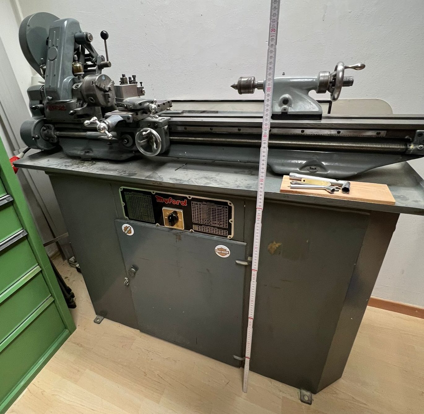
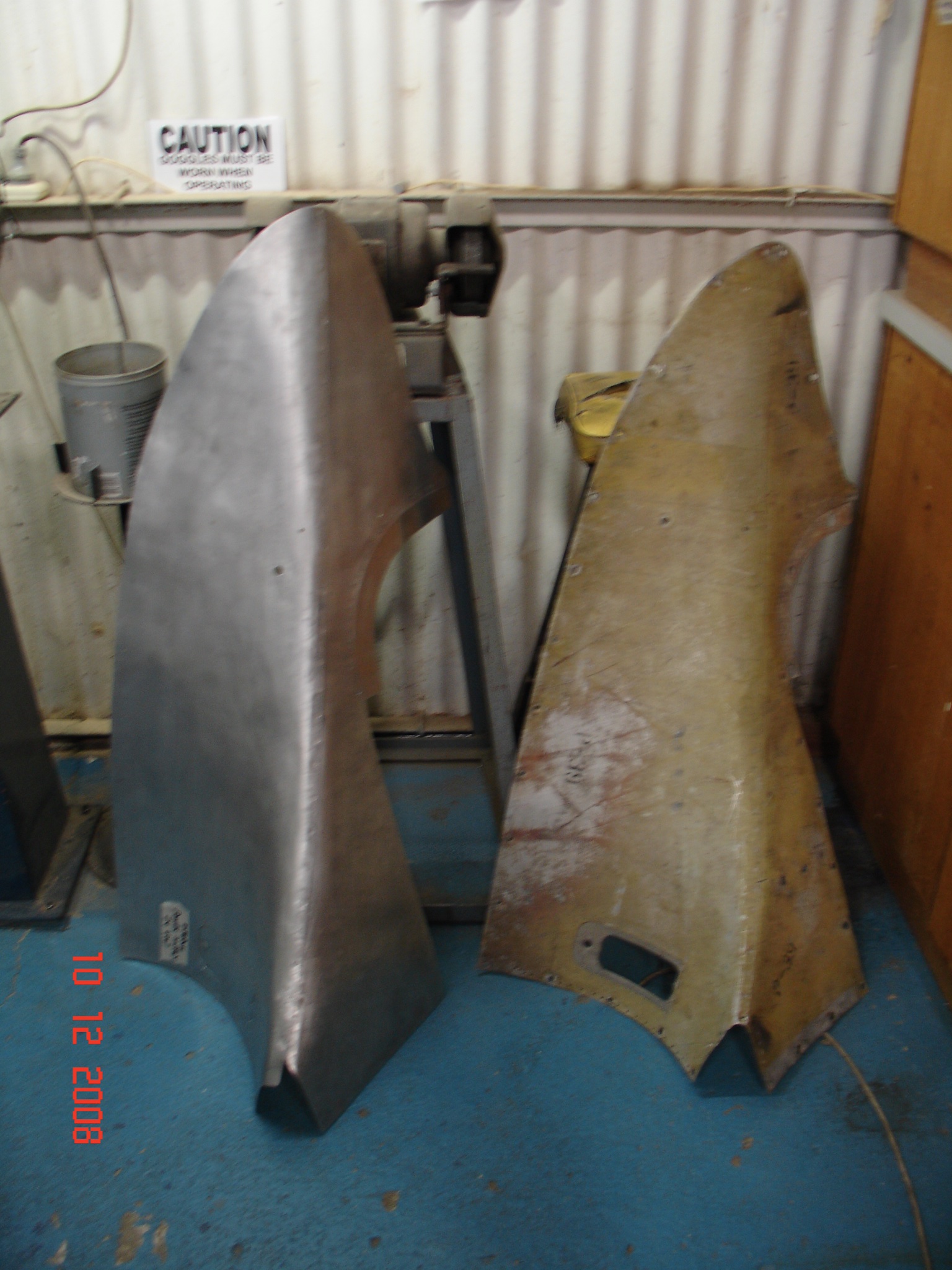
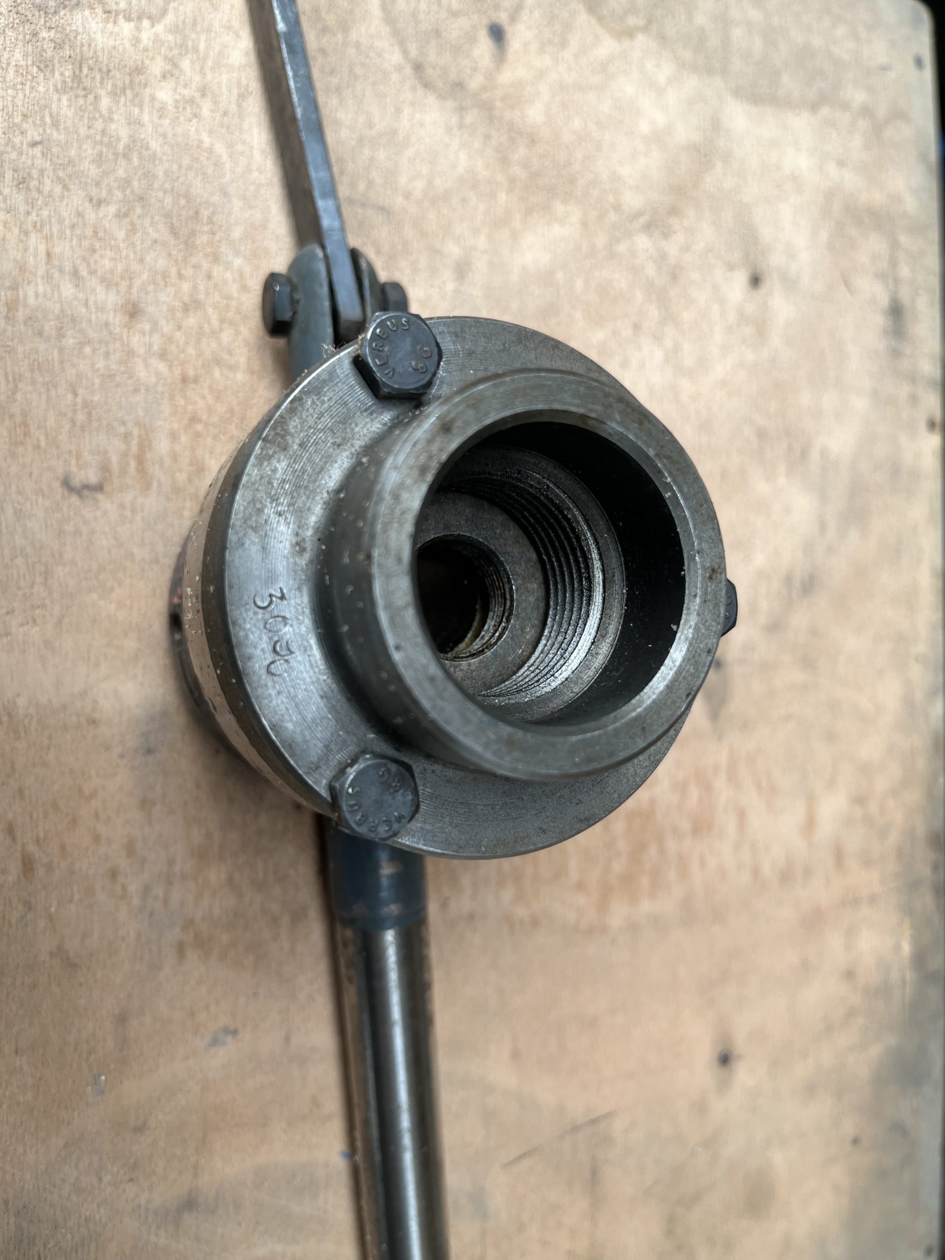 Here are the dimensions:
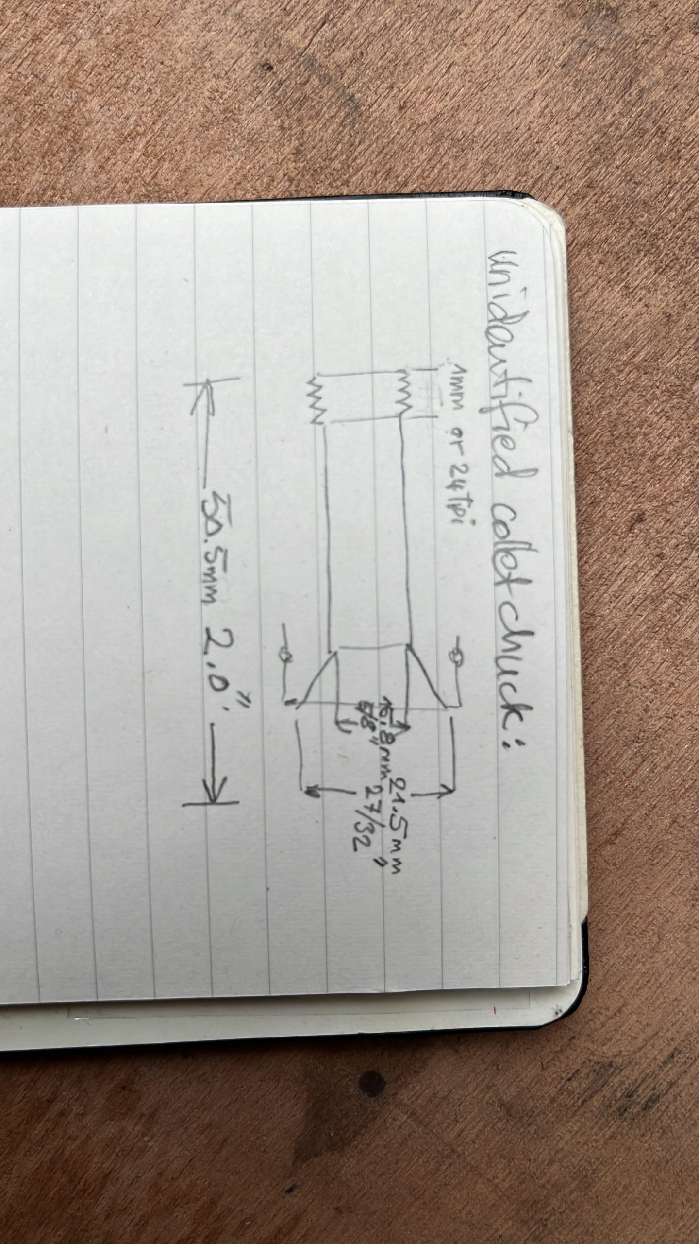
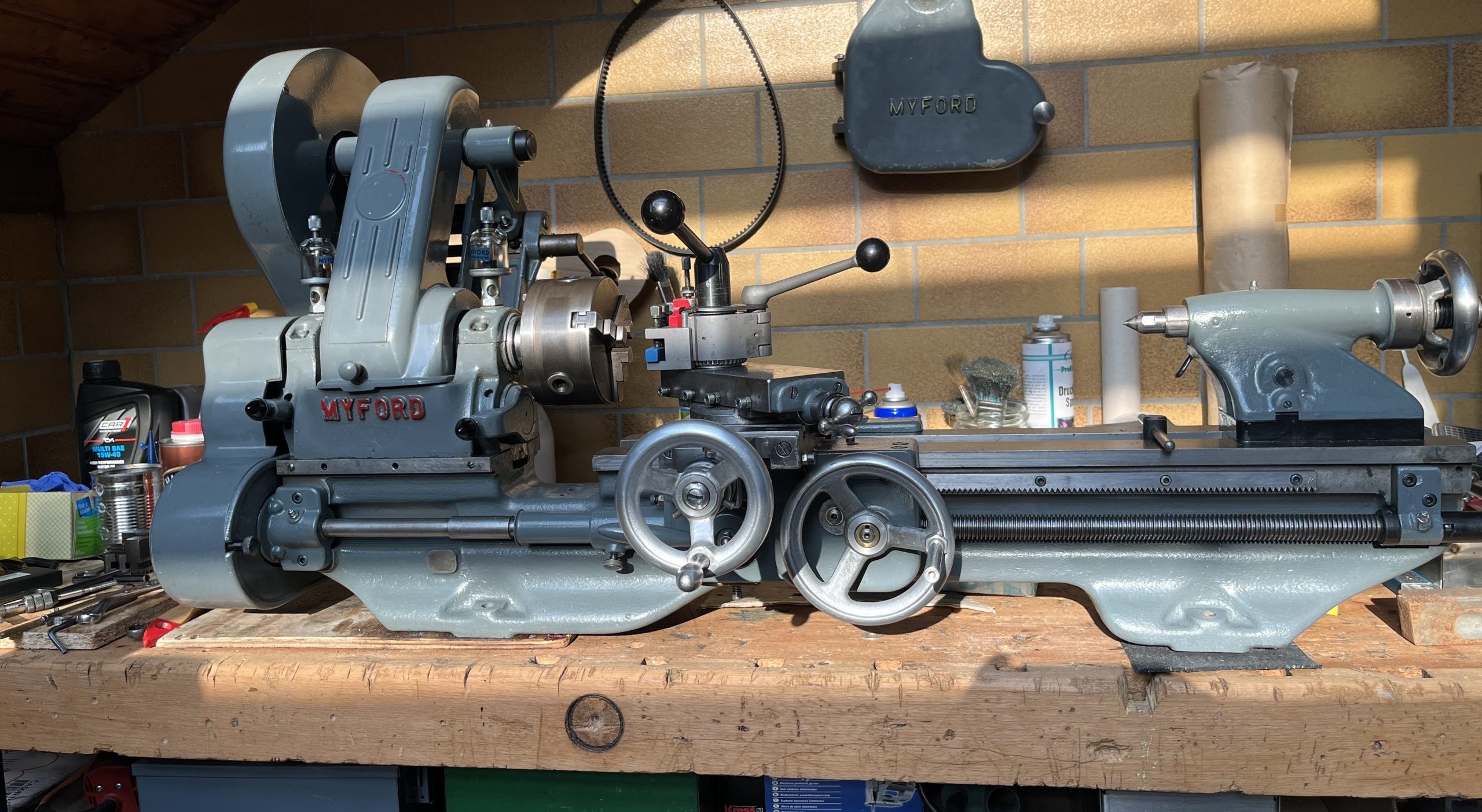
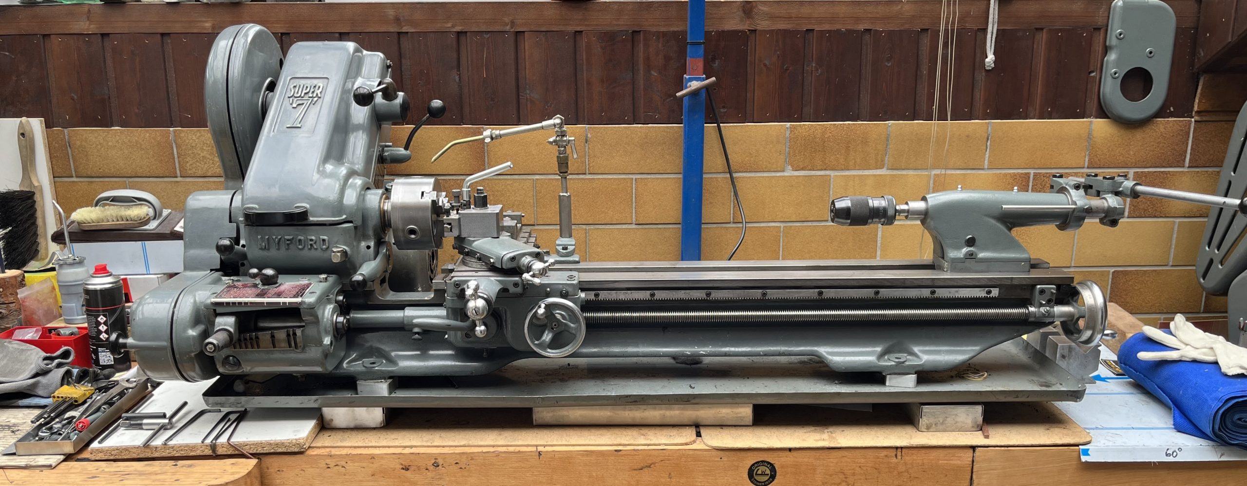
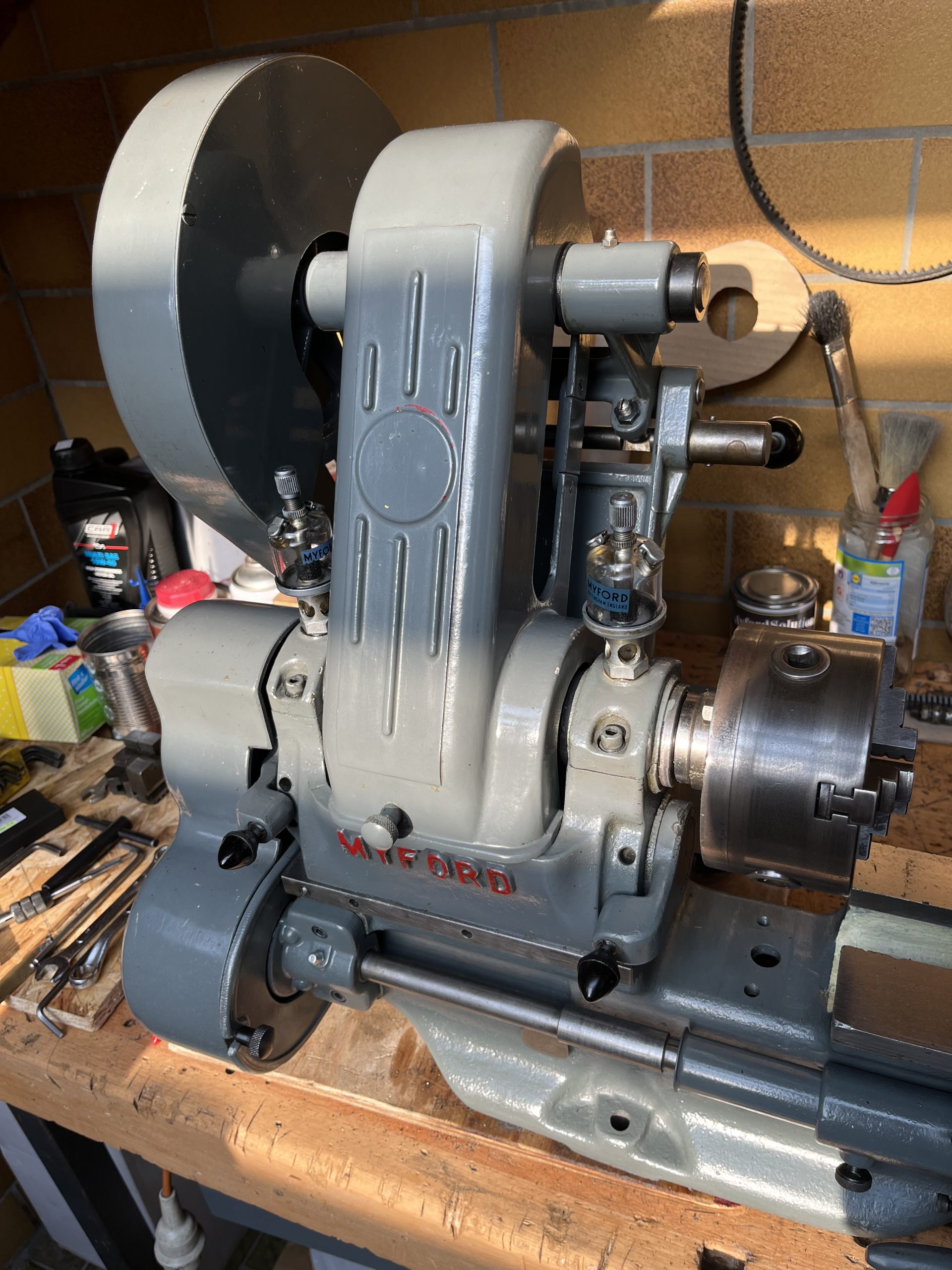
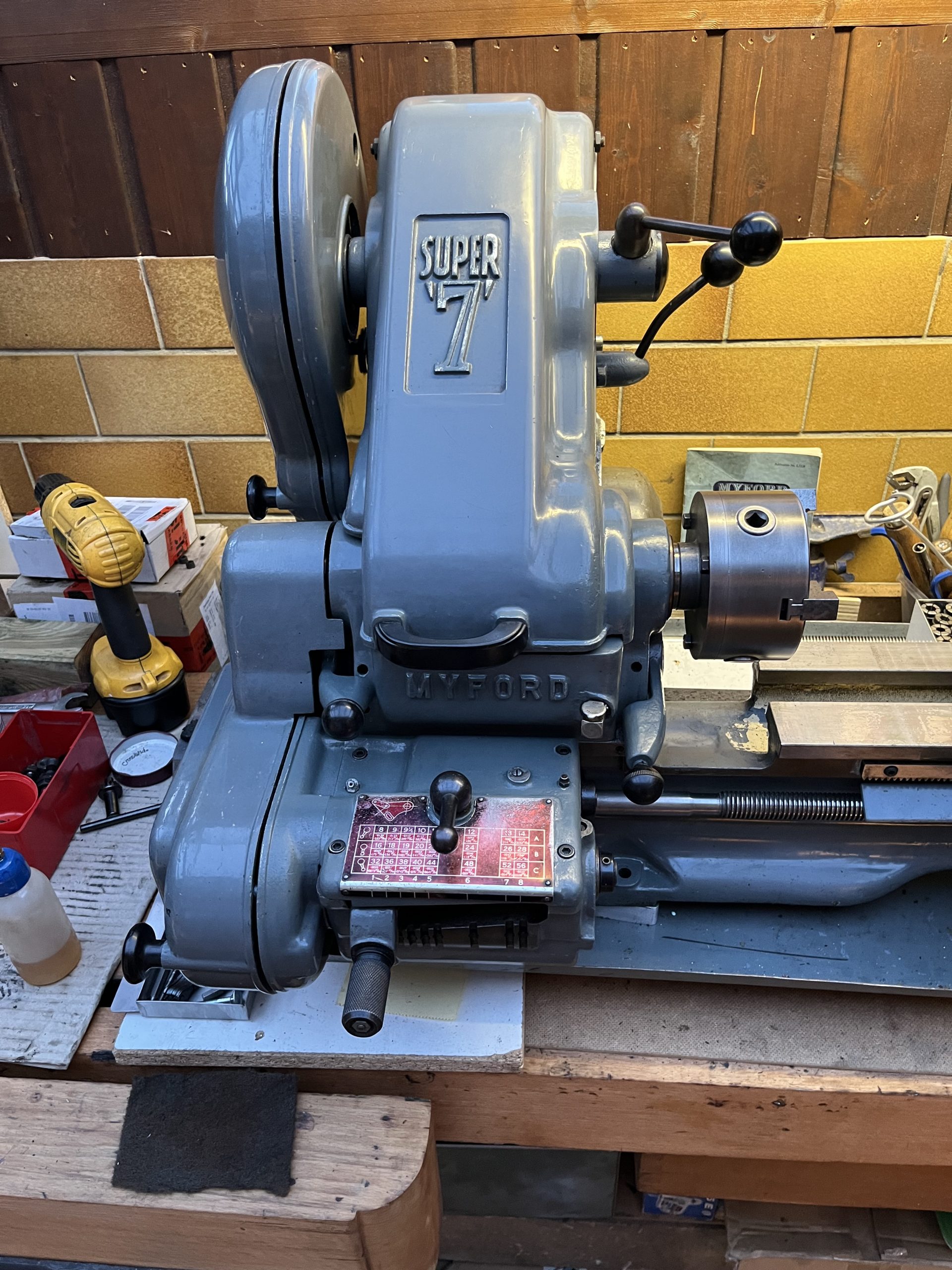
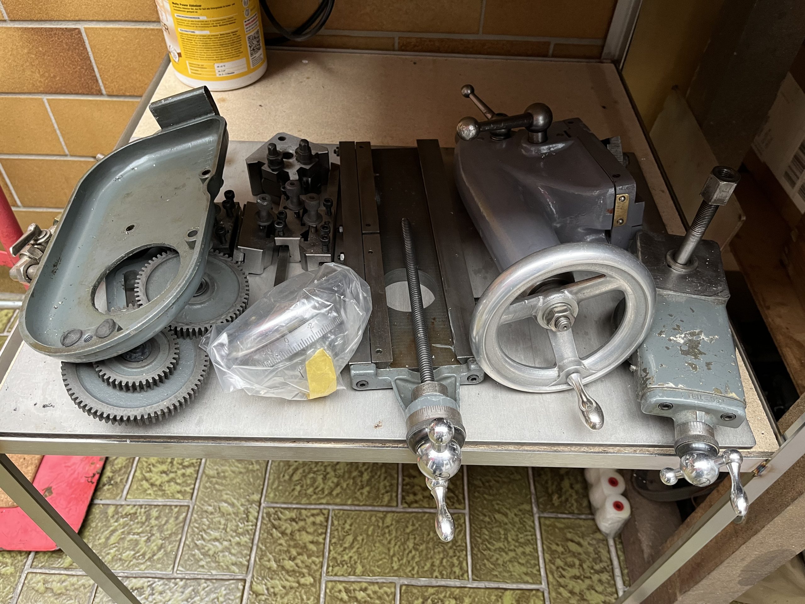
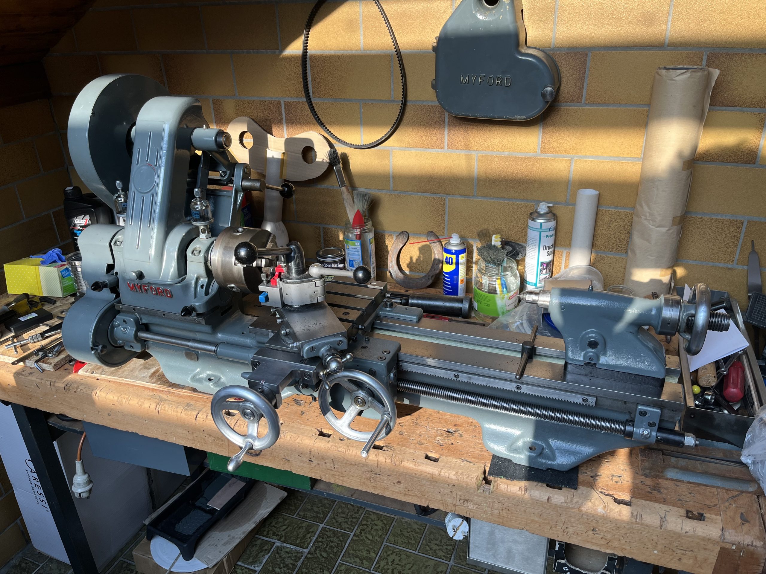 Now standing in the corner minus chuck, headstock and motor (stored underneath the bench!)
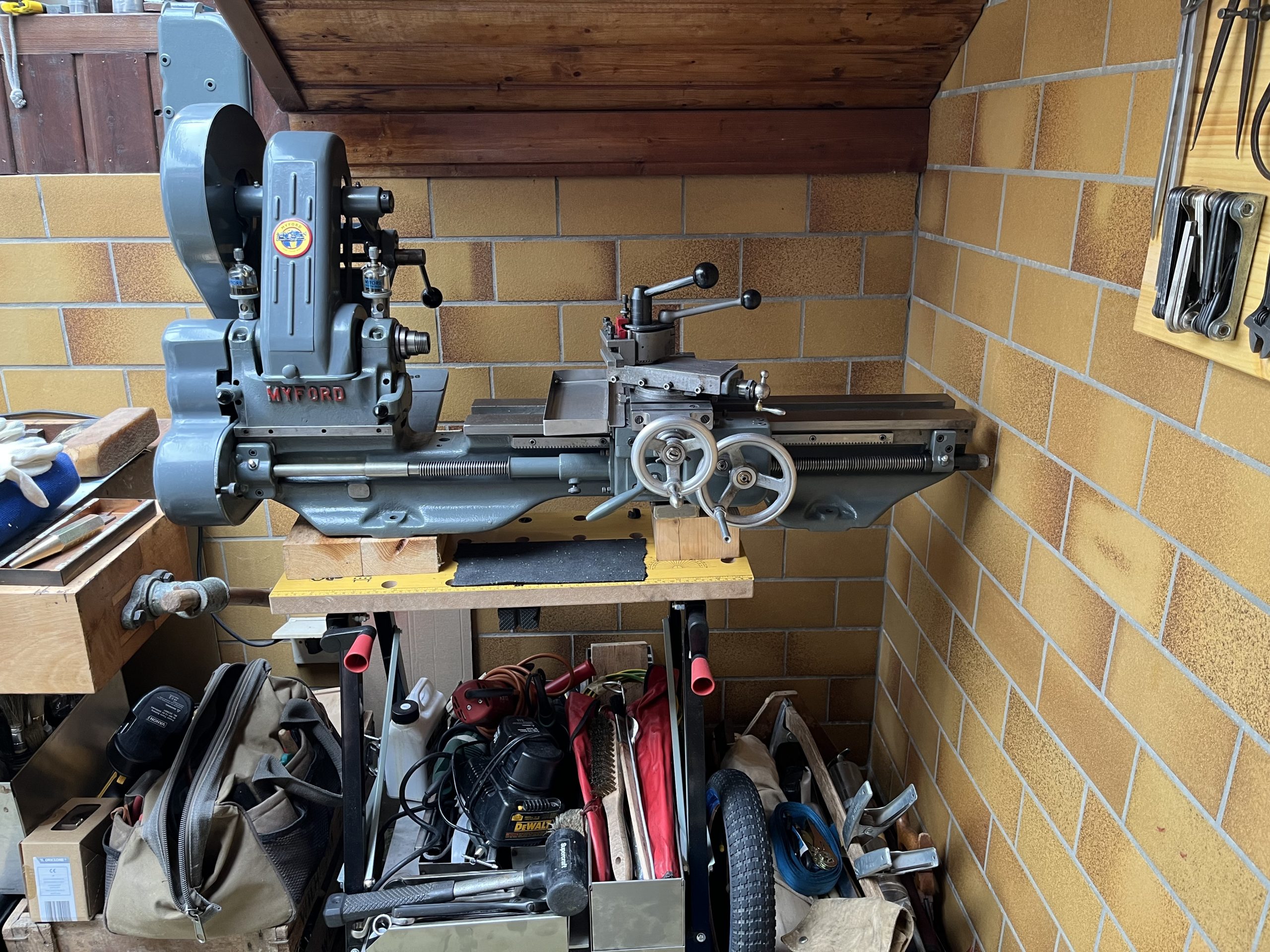
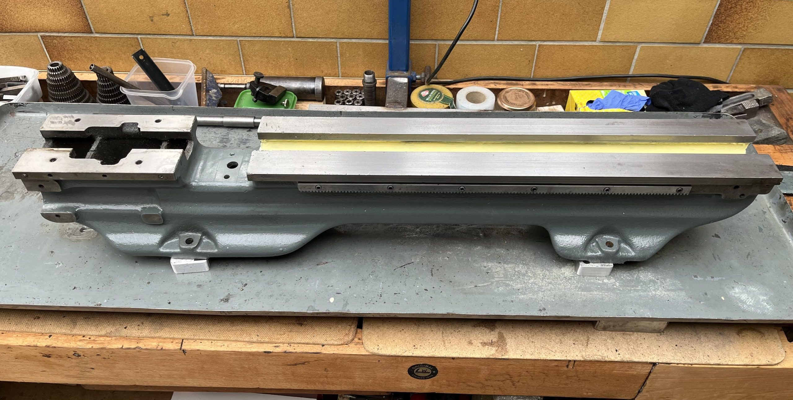


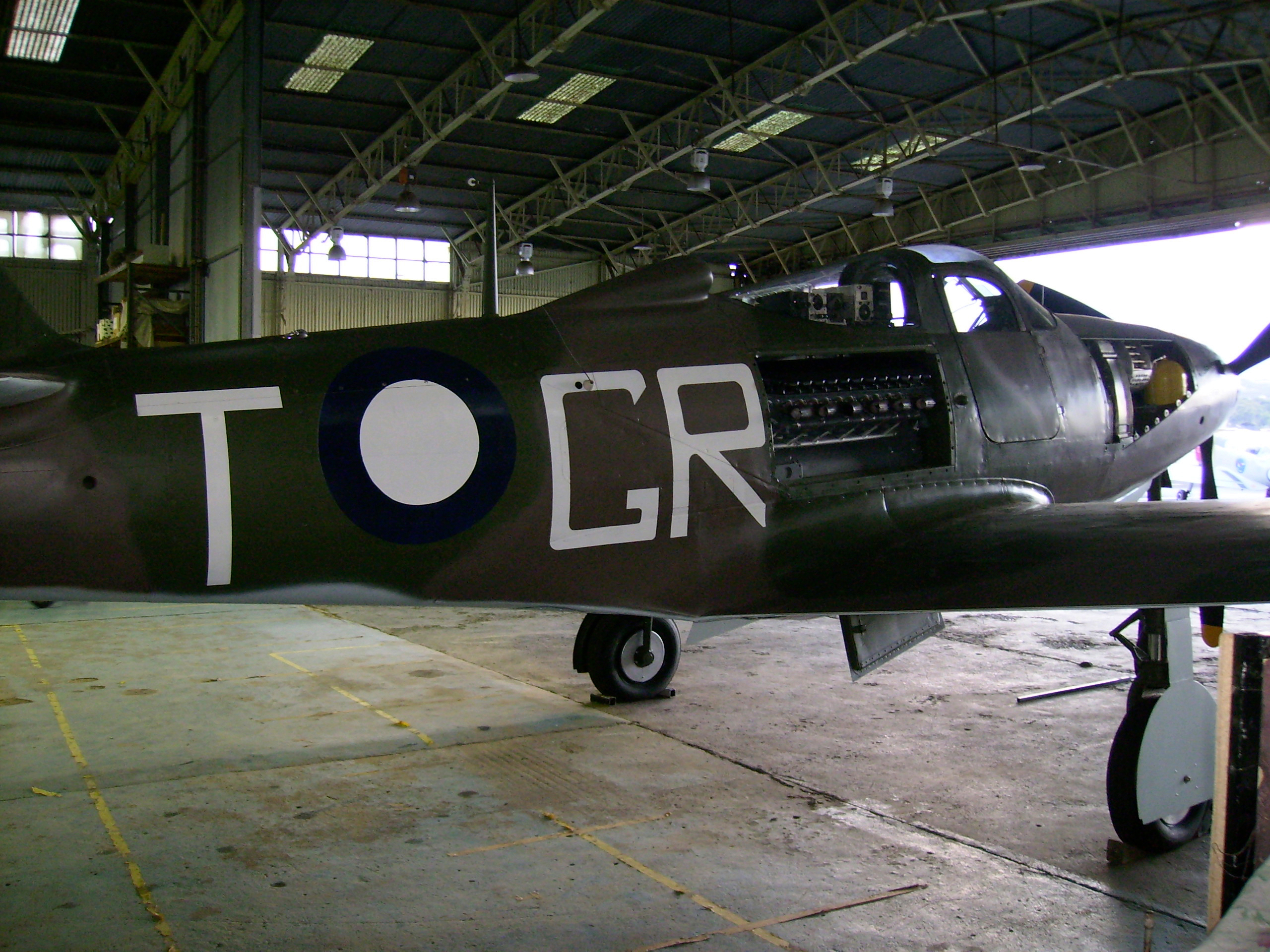
 Maybe at a later date I will even post a sound sample, who knows!


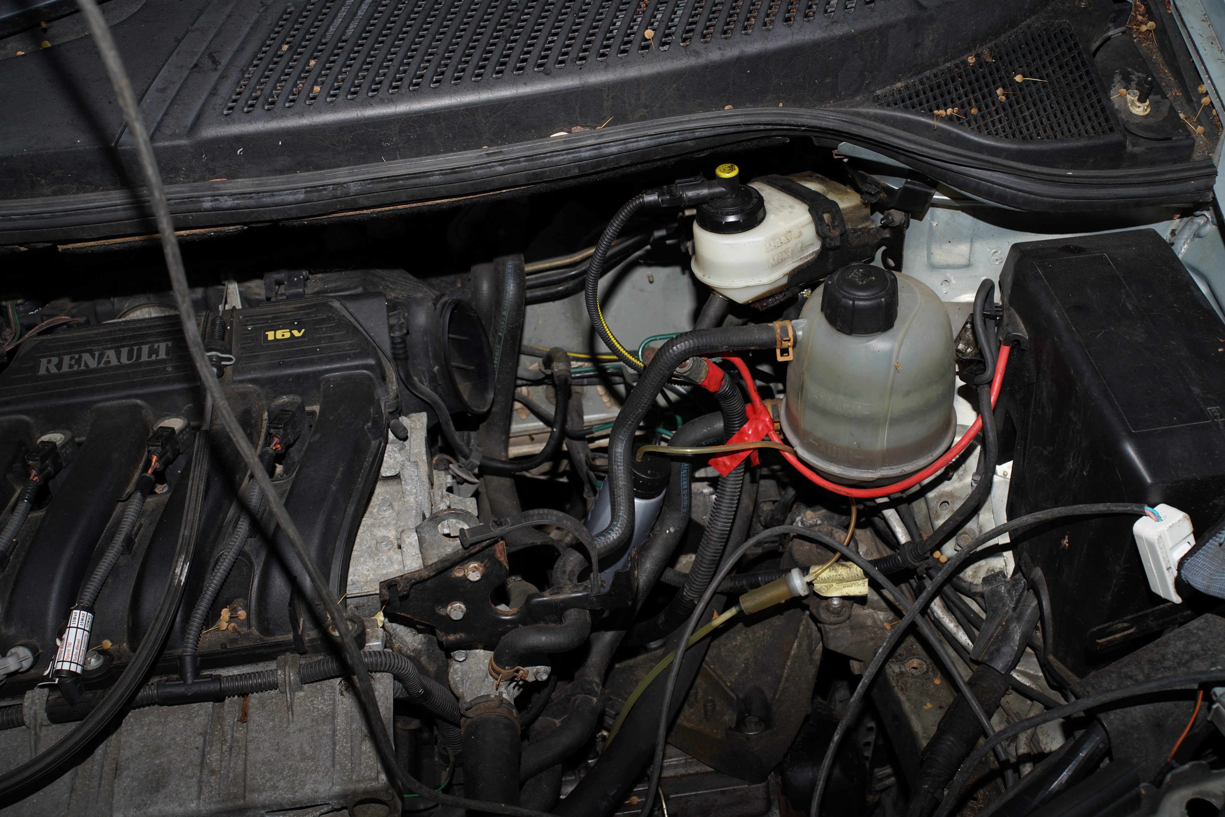
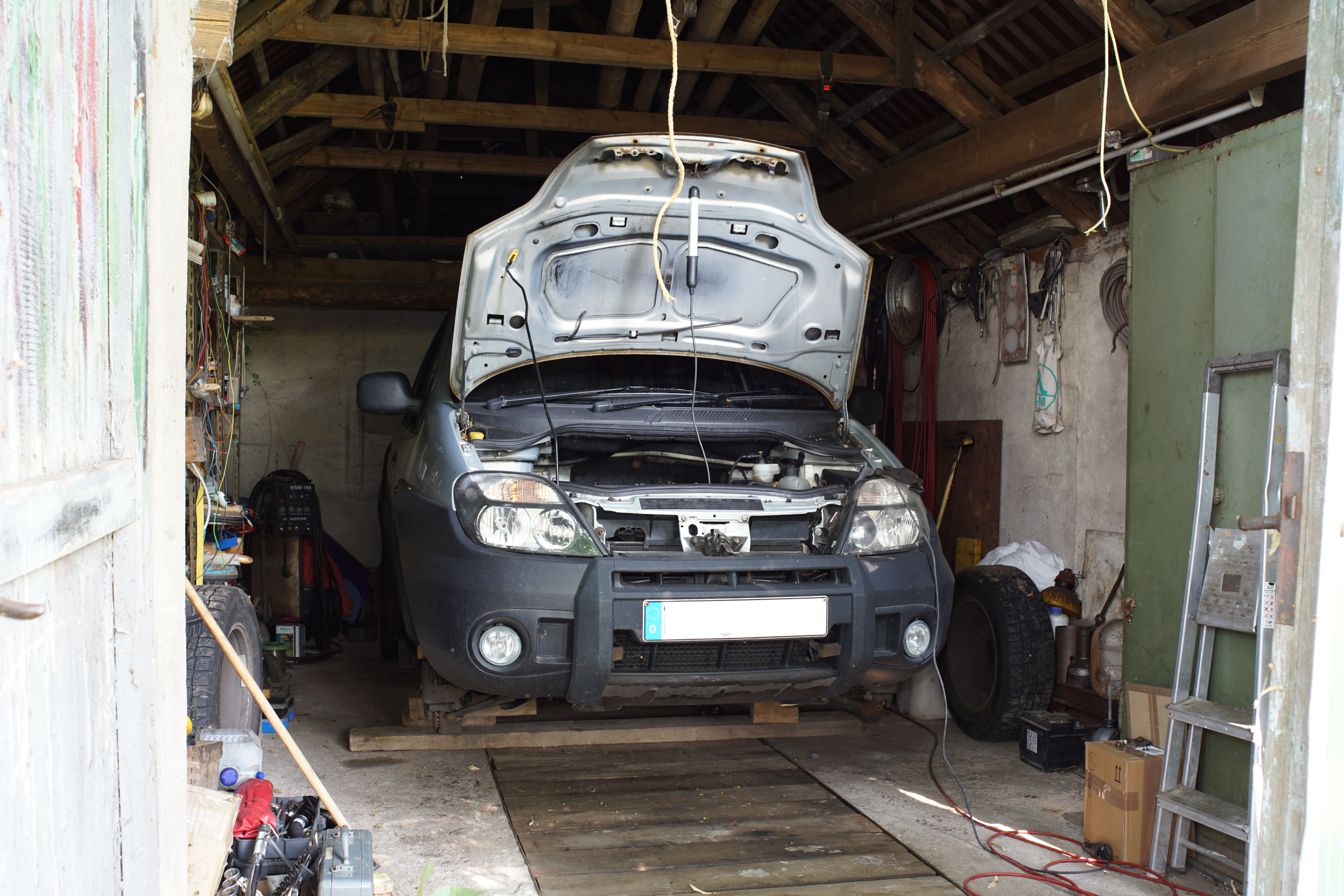 Let’s start at the very beginning: This is a Right-hand-Drive, 2001 Renault Megane Scenic RX4 2litre (permanent 4WD), bought in England, now registered in Germany and being used (when it runs again!) in Ukraine. No, this is not a new model that is hovering in the air, I have already taken the wheels off! That is a starting point for removing the gearbox, which involves taking the whole of the front sub-frame with the lower wishbones and the steering-box (rack and pinion) attached. The engine has to remain inside, as undisturbed as possible and the steering has to be locked in the dead-ahead position, also because of the airbag sensors. The steering-wheel gets locked first:
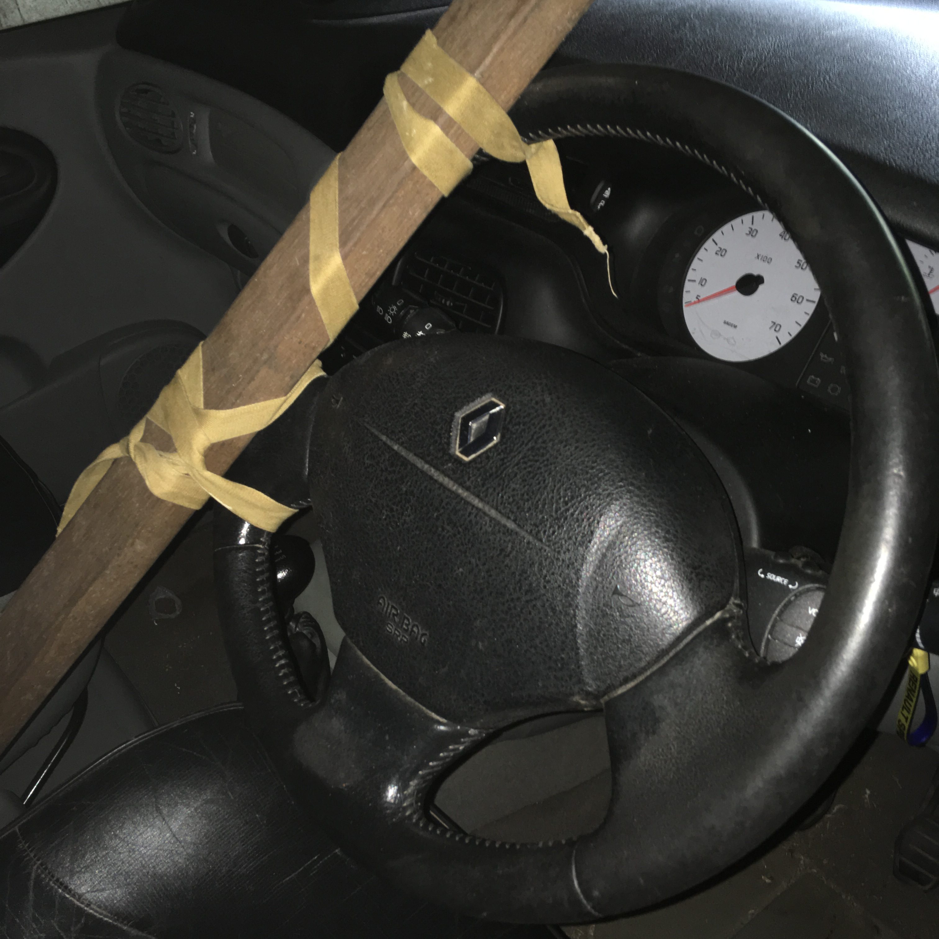