Diana large davits

Well, what a fiddle! Keeping all those bits together without squashing and distortion while they glue! One part was missing (28a, which was simple to make)but otherwise fitted together remarkably well for the first try. The next ones will rely on some spacers while building…. which is what the toothpick is for, by the way. EVERY time I picked it up, I somehow managed to squash the ends together 🙁 The part number 28a was nowhere to be found, but was easily made – the front panel, a squared ‘U’ shape.

Carefully placed (it’s not finished yet!) where it will go along with the other three large davits.

Edges painted and tried out with the David arm for fit:

For the full report, please go to https://thingummybob.com/modelmaking/building-dom-bumagis-diana/

Diana storage boxes on deck and companionways 2

A little progress has been made, all the storage boxes are now fitted on the starboard side and another of the companionways, still without the tubular frame for the canvas cover or the hatch – they will come in due time.

Here is the step-by-step building process for the companionways: I noticed that the steps were too wide as drawn to allow the companionway to fit in the holes provided on the decks, If they would simply be glued on to the cheeks, so the only way to fit them would be to cut out the sides and fit them like one would with a real wooden staircase, captured between the cheek-pieces! See below:


Folded together and glued, without the top frame, but the front of the box left open:

So here are the other 4 assembled and ready to be fitted – all lined up like peas in a pod 🙂


Below with and without frames…

And here they are with the top frames and the edges painted appropriately (with Aquarell paints) and with a 1 Euro-Cent piece for size comparison. The footprint of the staircase is ca. 8mm long.

For the full report so far, go to https://thingummybob.com/modelmaking/building-dom-bumagis-diana/

First companionway, storage boxes on the port side, strengthening ribs and aft superstructure.

Here is the first companionway, as yet without painted edges etc.

Here a couple more pics from different angles (the same companionway)

And here installed in the forward deck, as yet without hatch and wire frame, but with the edges touched up!

Next comes the addition of the strengthening ribs around the inside of the hull ‘walls’, the storage boxes on deck and the aft superstructure, again not yet fitted with its railings – mind your step!

Oh well, the lighting isn’t great, but you get the idea 🙂

For the full report, please go to https://thingummybob.com/modelmaking/building-dom-bumagis-diana/

75mm Gun platform buttresses on deck

The 75mm gun platforms have to be done on the upper deck, which turned out to be a real pain. On all the other models and drawings I have, these outriggers are drawn and constructed as a plain buttress, without reverse curves at the sides. Take a look at the pics and you will see what I mean. Definitely a challenge to build – at least the aft ones only have one side with the reversed curves.

Here is a construction series of that rear one, to show the difference between the straight and the curved side (huge magnification, about 4x life Size?)

And now with the ‘wing’ formed and stuck down from the inside and out.

And how it fits on the starboard side, prior to fitting the tubes through to the portholes and prior to touching up the white edges:

Now the other side is also done!

Slowly, slowly I move forwards. Our baby is due in a few weeks, so I’d better get on with it!

For the full report, please go to https://thingummybob.com/modelmaking/building-dom-bumagis-diana/

Hull sides and Hawes pipes, anchor positions as mounted

Ok, so the port side is now on, after a load of trimming and adjustment, but despite that, looks quite good, if not exactly perfect:

One of the storage bins (at huge magnification), which I decided to have a trial at building, despite there not being any help or diagrams from the instructions – I had to resort to the internet to have an idea how they really looked:

Having fitted the forward portion of the hull next to the forward deck, I also wanted to test the fit of the bulges which house the mounts of the Canet 152mm/45cal. Guns. It was not bad, but did need to be ‘modified’. However, I believe that was in part to my slightly oversize deck portion that stuck out. We will see, as all the others have now been trimmed to size! Amazing what half a millimetre can do! Difficult is the double curve aft, where the bulge ‘merges’ into the side. Next time, I’ll also bevel the inside edges to get a smoother transition 🙂 At a ‘normal’ distance, it still looks pretty good, though:

Here the whole starboard side showing all the installed gun ‘pods’

The inside of the starboard side showing the Hawse pipe, but before the glazing and the bars on the front portholes.

Those sides have now been glazed and the bars on the forward portholes near the anchor have been added, too. Tomorrow the wires on the hatches for the aft gun will be added, the rest of the gun mounts will be fitted below deck and maybe the starboard sides of the hull will be glued in place!

Now the same from the seen side!

And completed without cover on the Hawes but reinforcements for the Anchors and the Hawes built up

Still a bit of touching up to do on the hull where the waterline meets the sides.

Through the portals you can see the gun-mounts waiting for the barrels to be fitted, when it is ‘safe’ to do so!

For the full report, please go to https://thingummybob.com/modelmaking/building-dom-bumagis-diana/

75mm Canet guns, Hull sides glazing and detailing before fitting including Hawes build

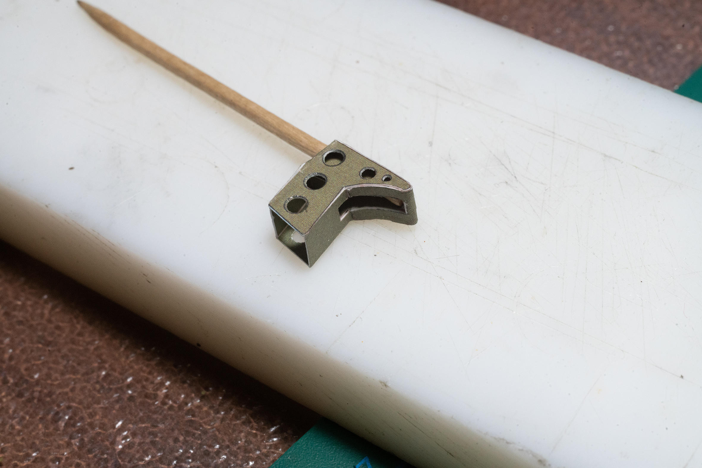
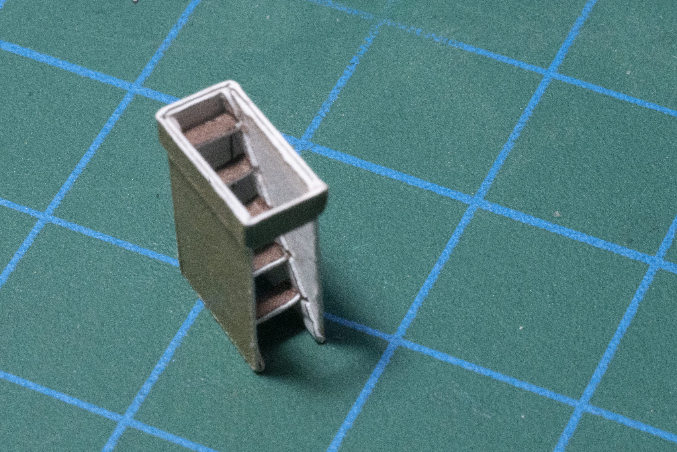
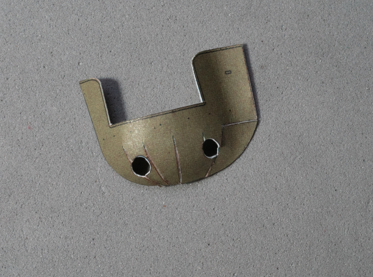
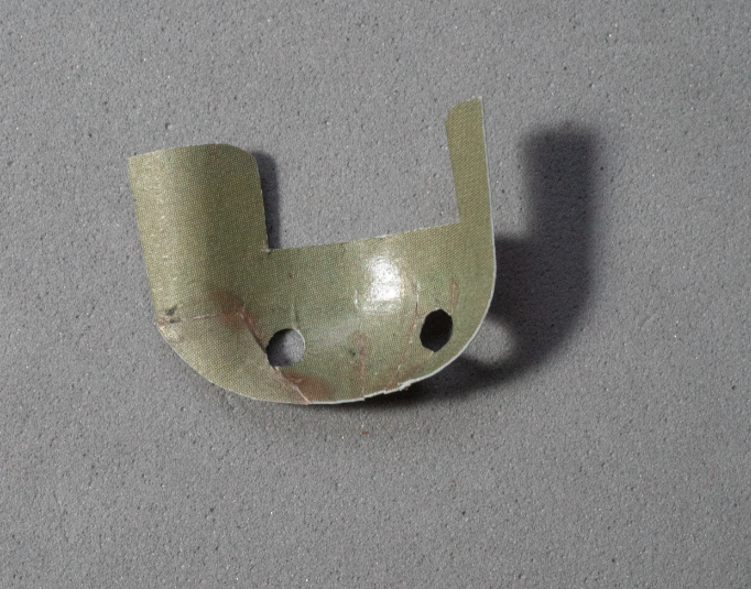
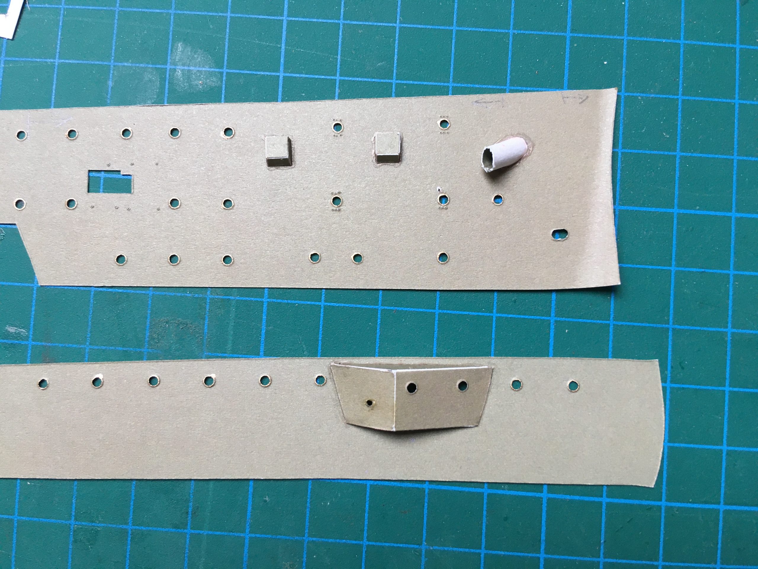
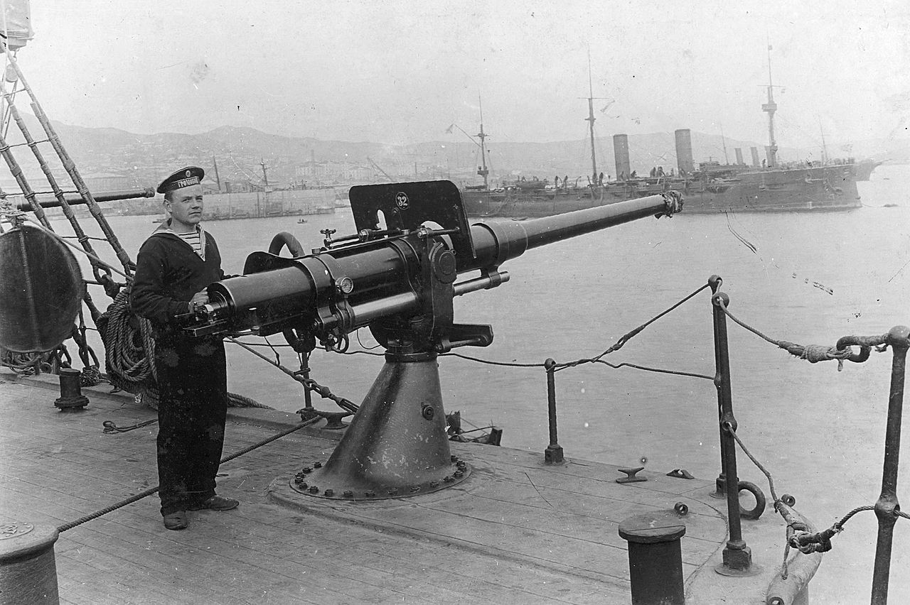
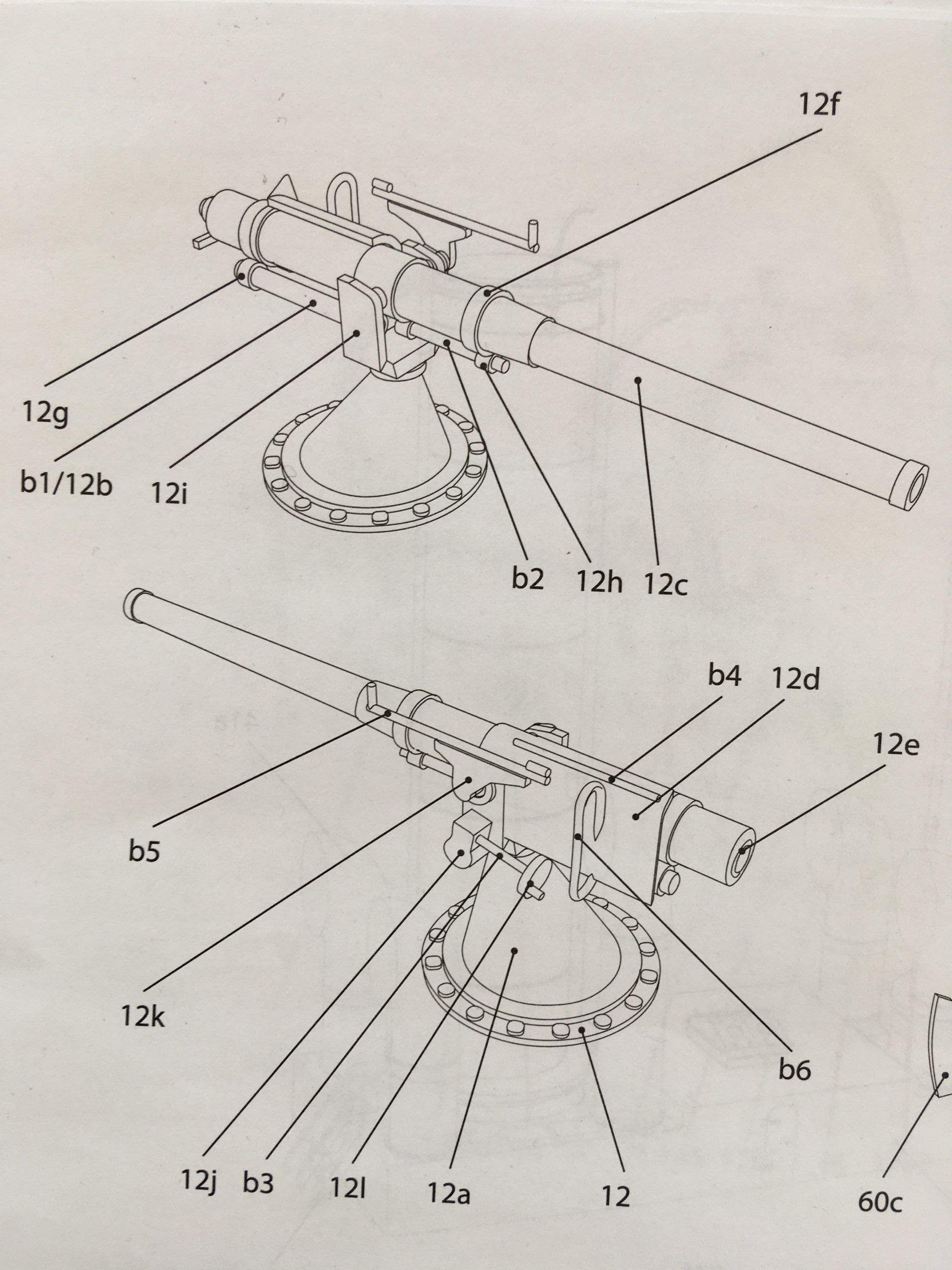
Work on the 75mm guns has begun, but I’m still not completely satisfied. The drawings from the instructions are not very conclusive, but I assume that they don’t expect any greater need for detail; but if they include parts, it should at least be clear where they go and how they look when finished: That goes for a lot of the drawings, which out of economy of space, the reverse side of many views is omitted, leaving the builder to fantasize where the parts go, even if they are different to the side shown in the (very good) drawings. Here a few pics of work in progress and one of the reference pictures I found.


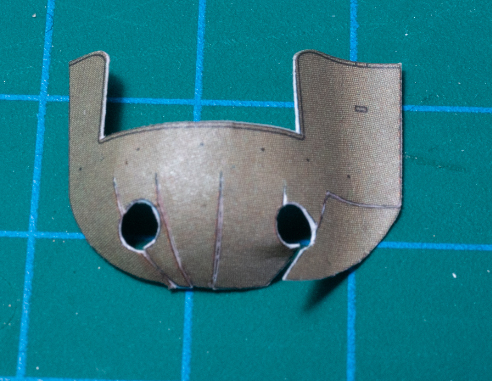
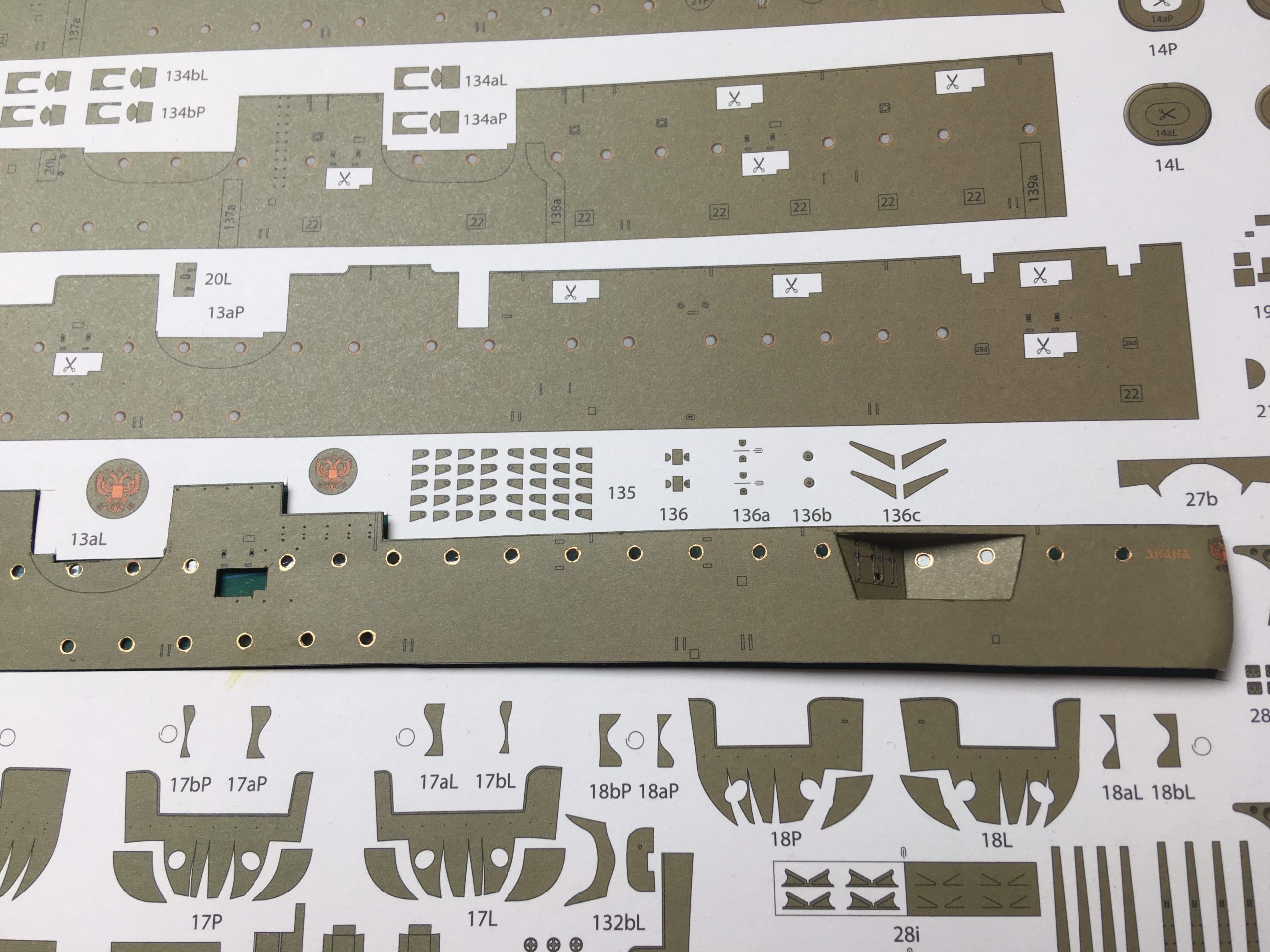
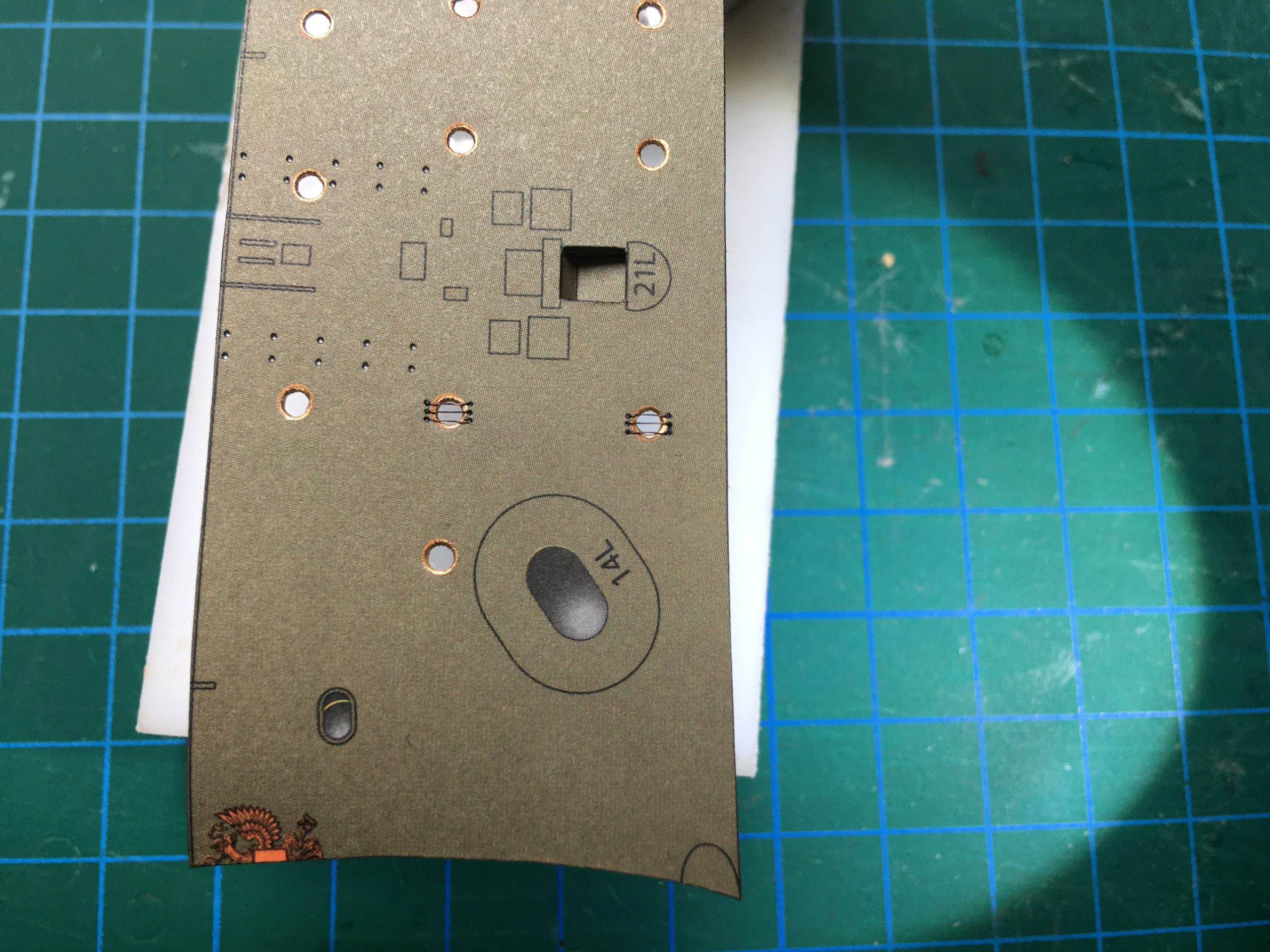
Excellent diagrams from their kit – which, however, leave a few questions:

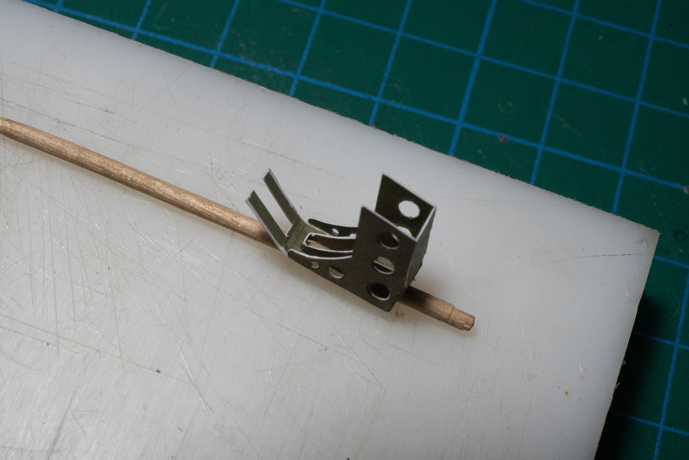
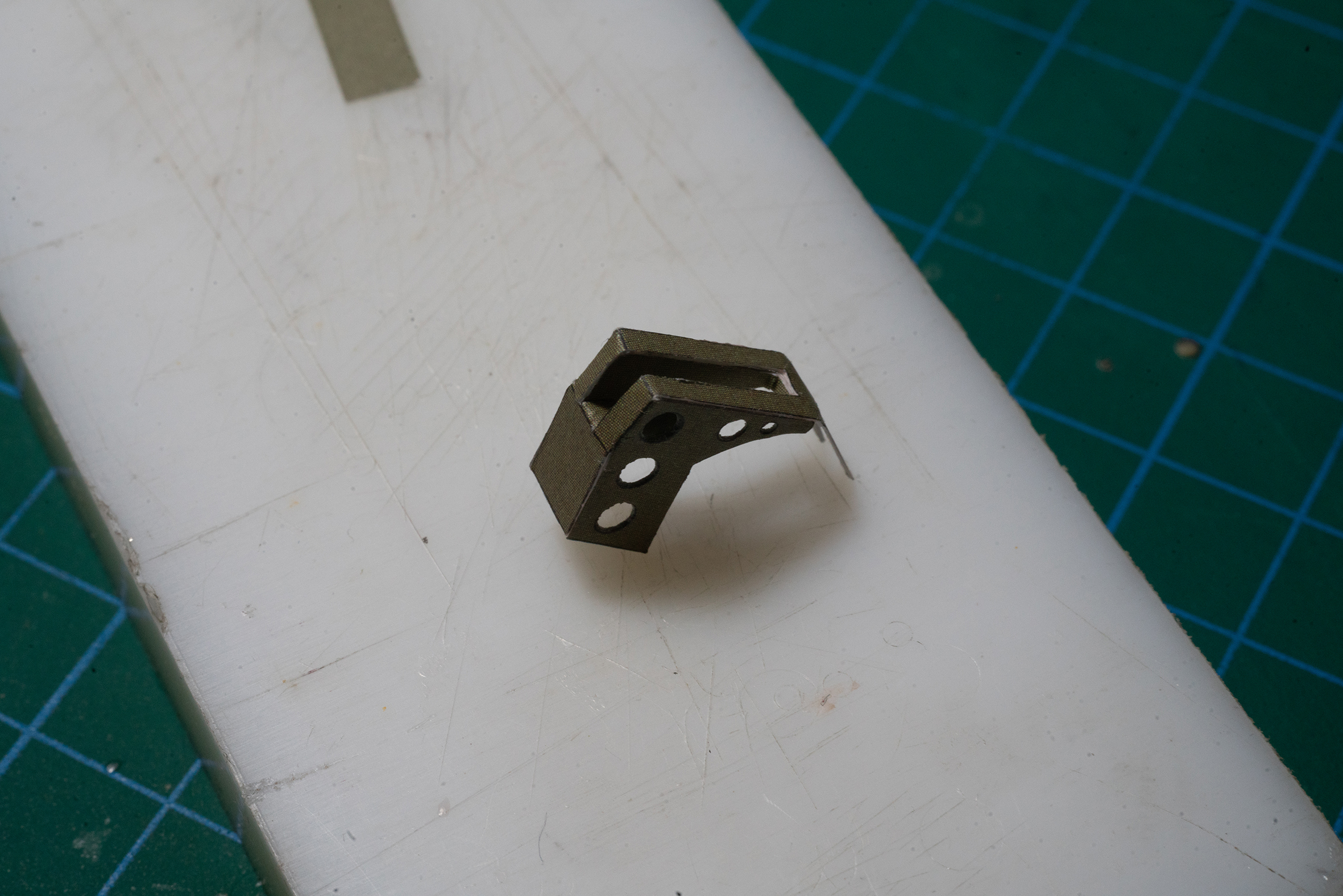
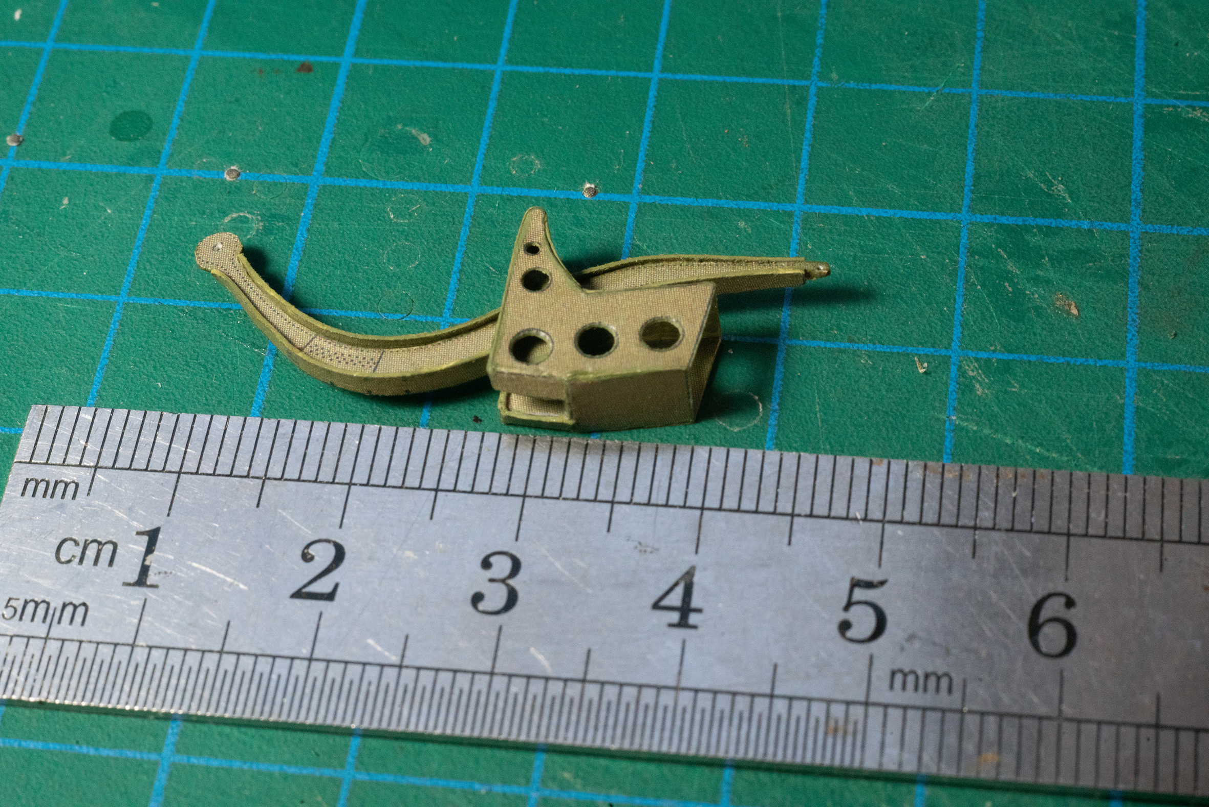
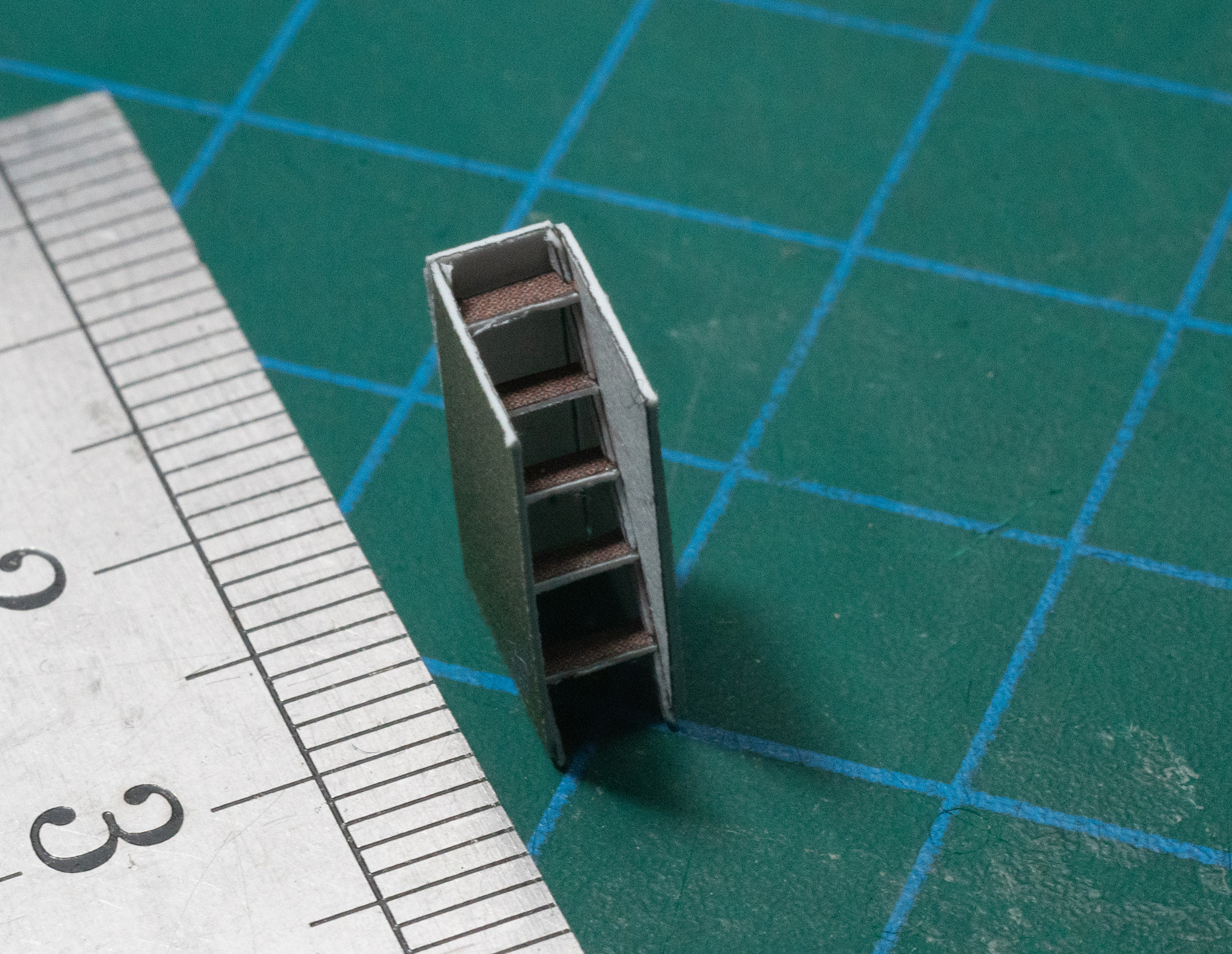
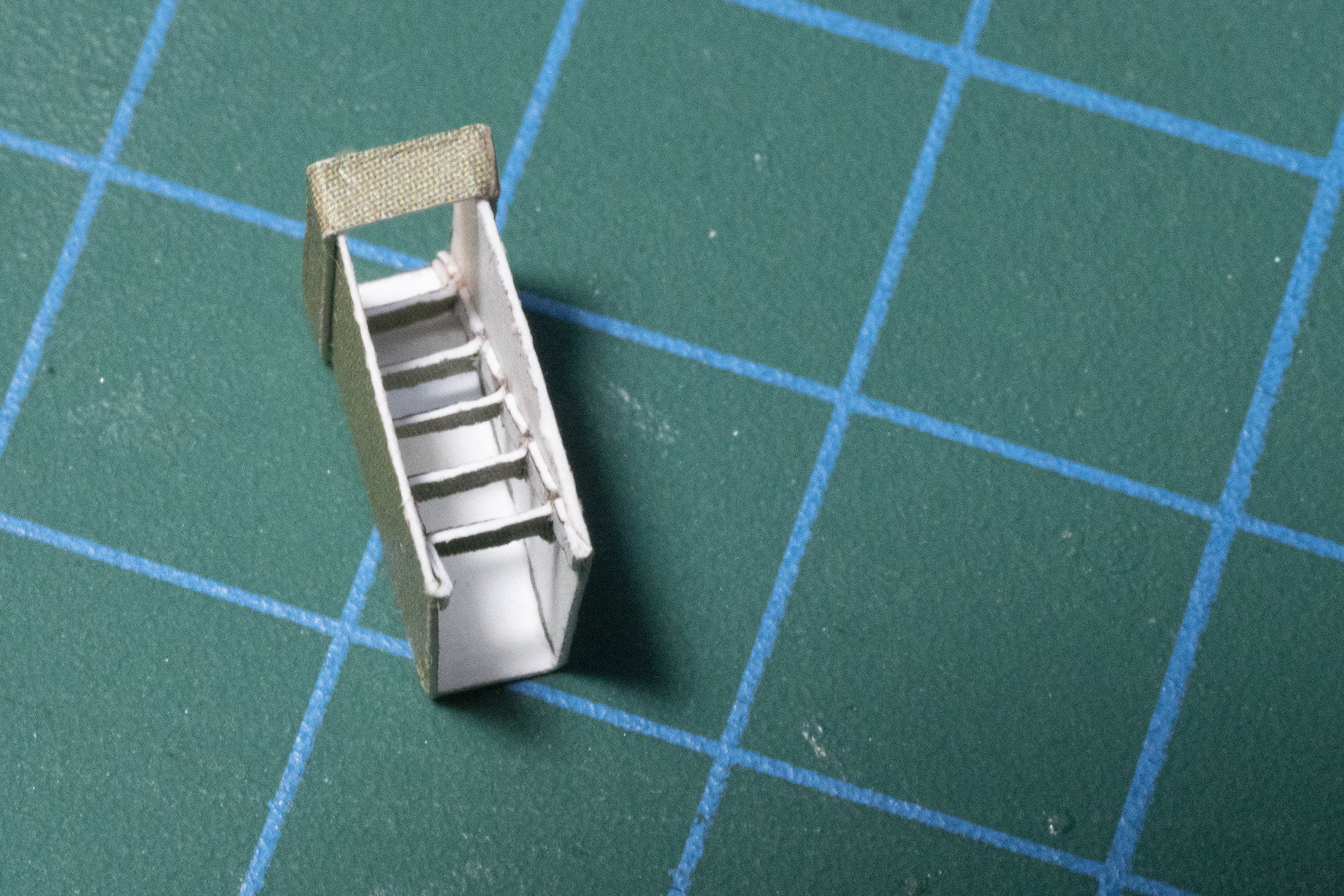
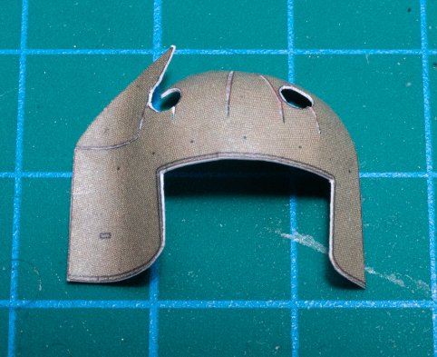
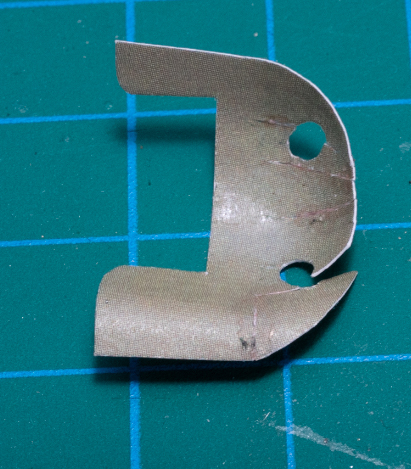
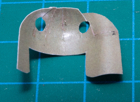
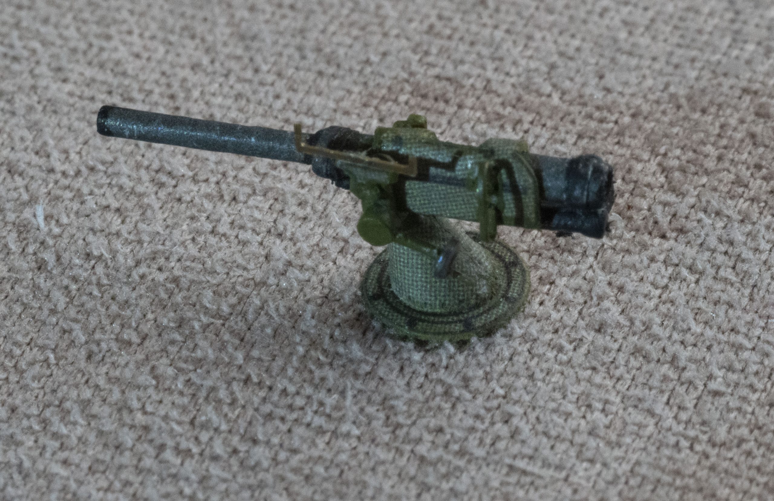
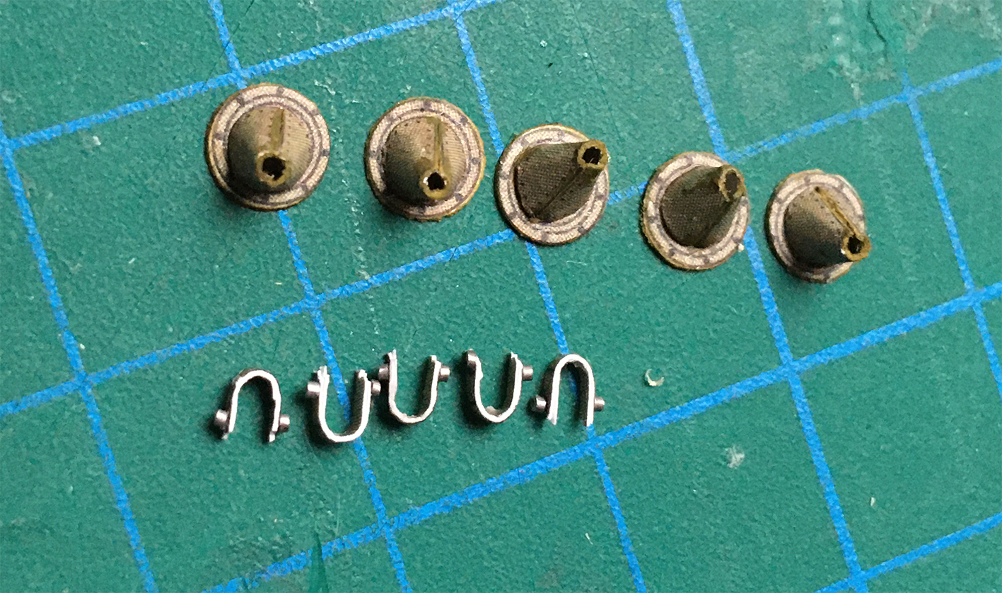
My first efforts at the 75mm at huge magnification:

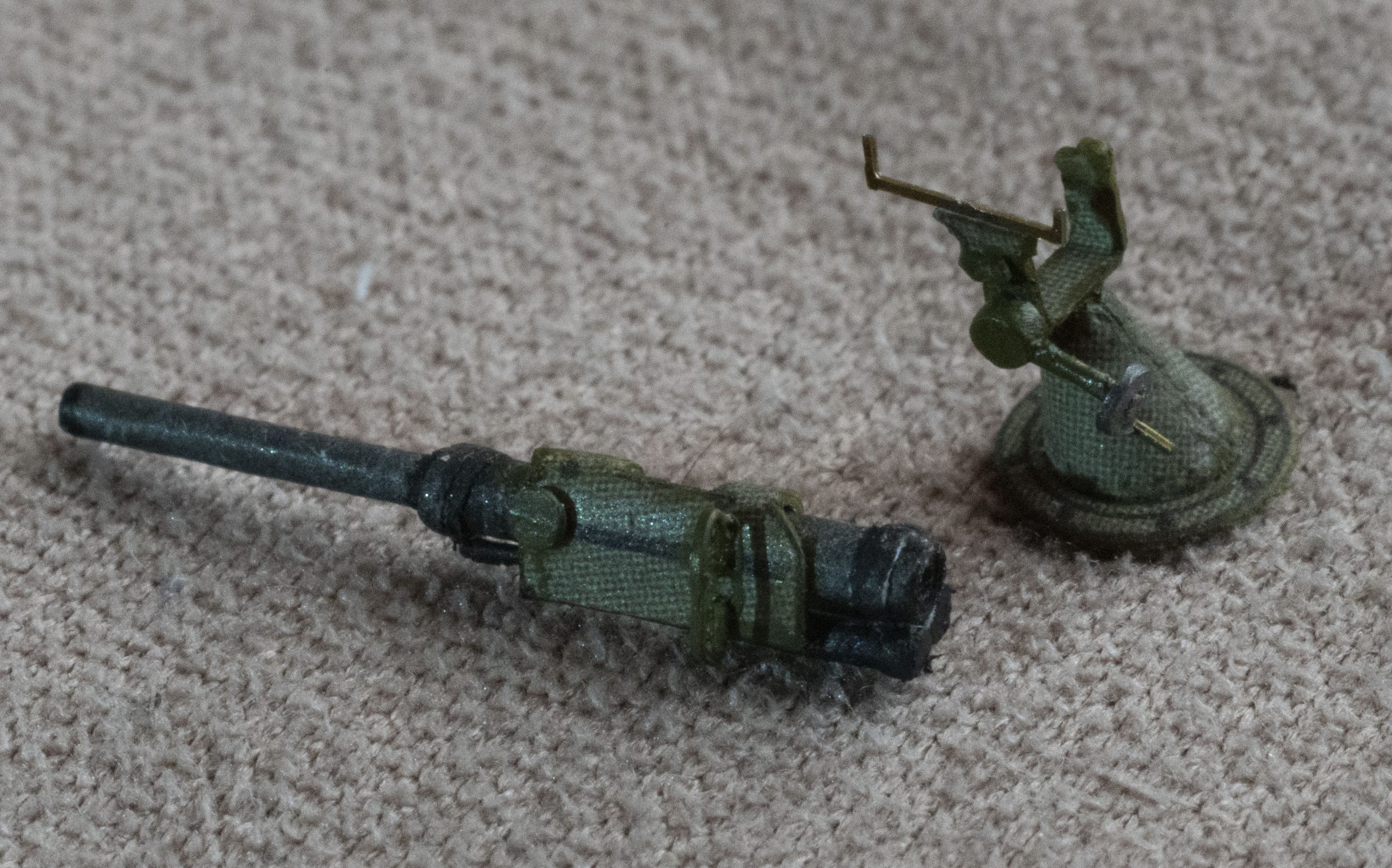
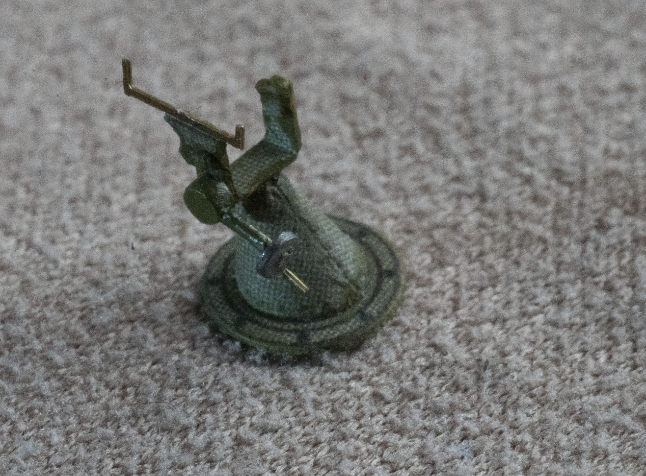
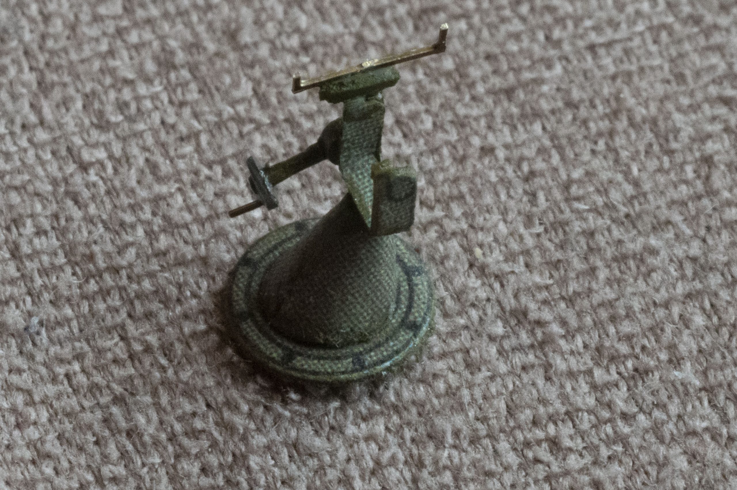
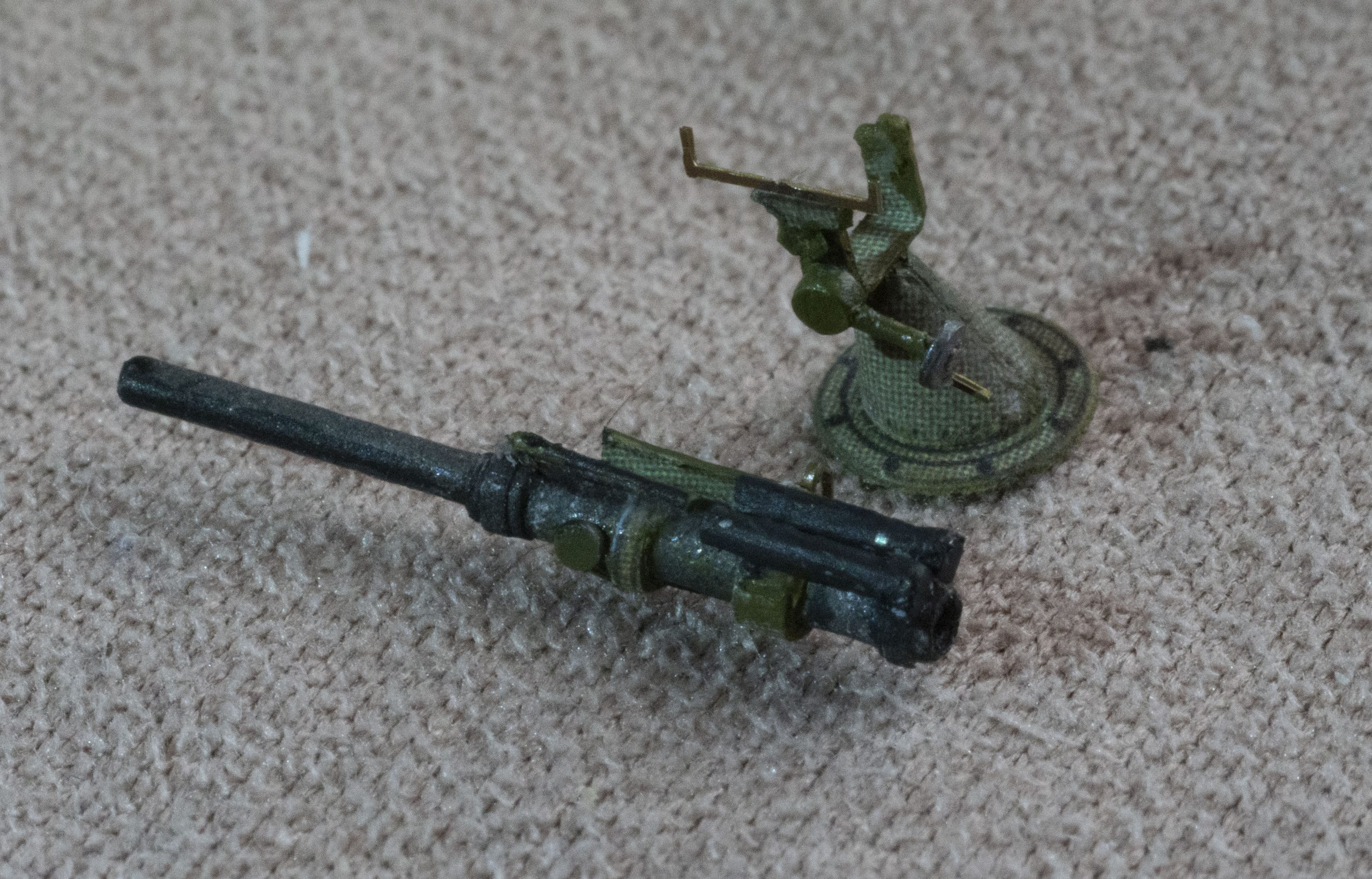
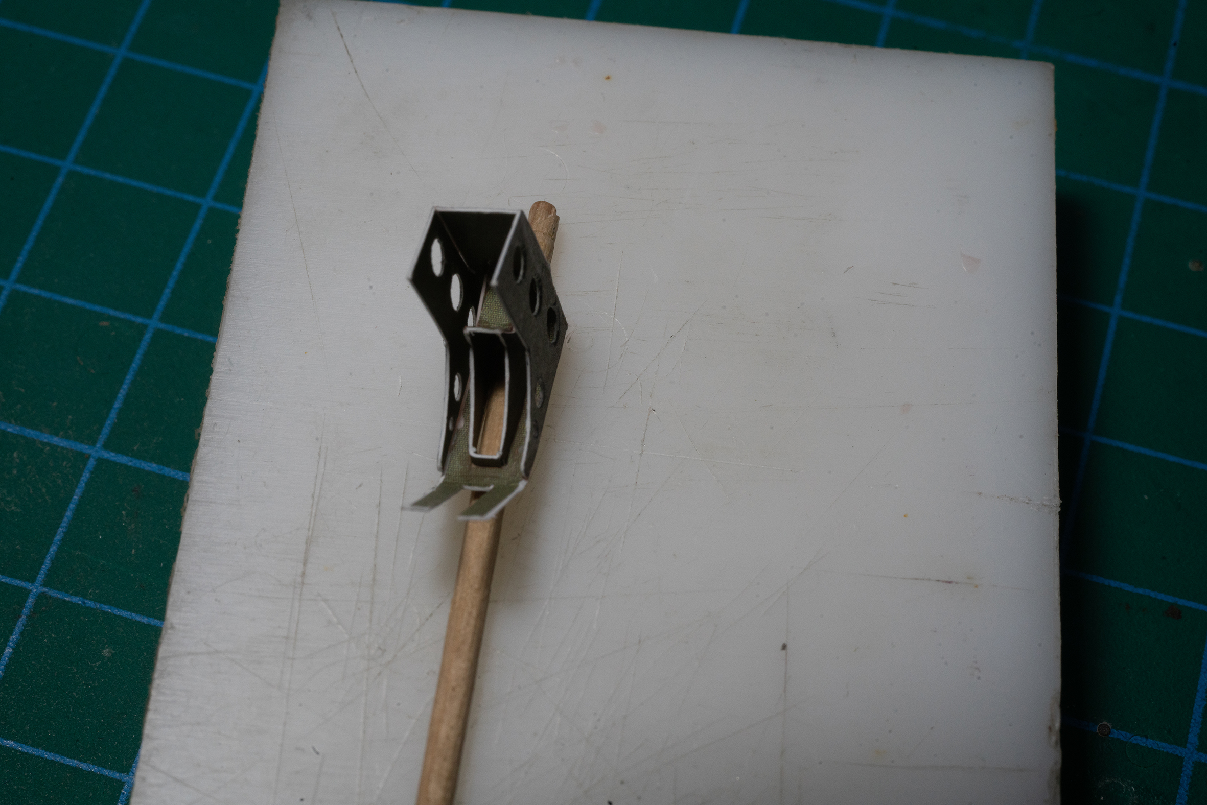
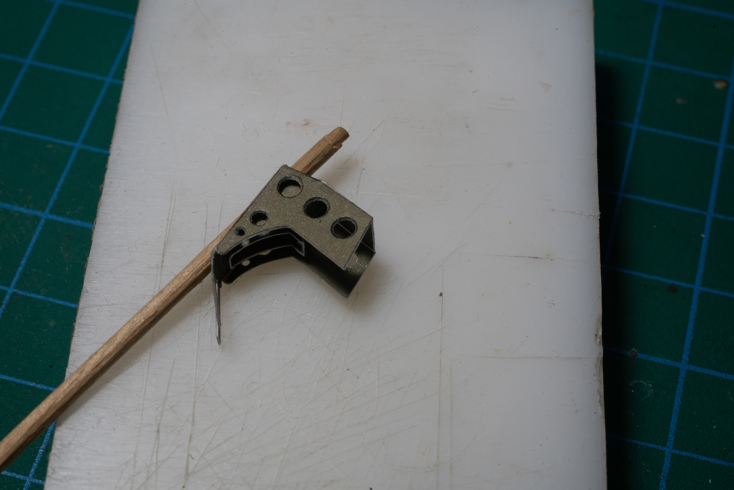
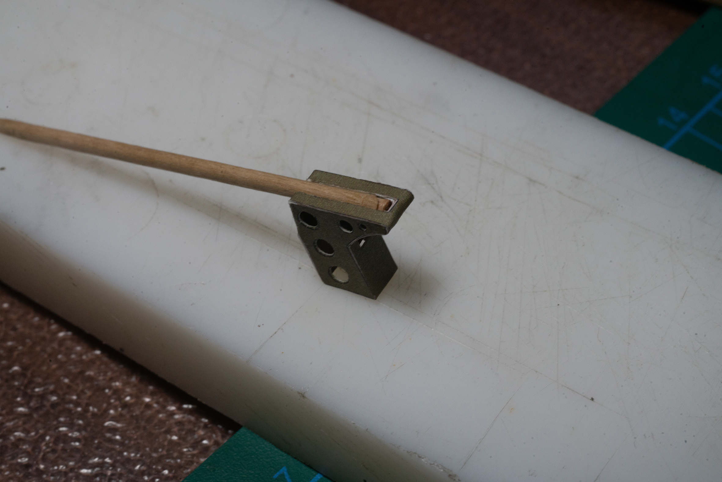
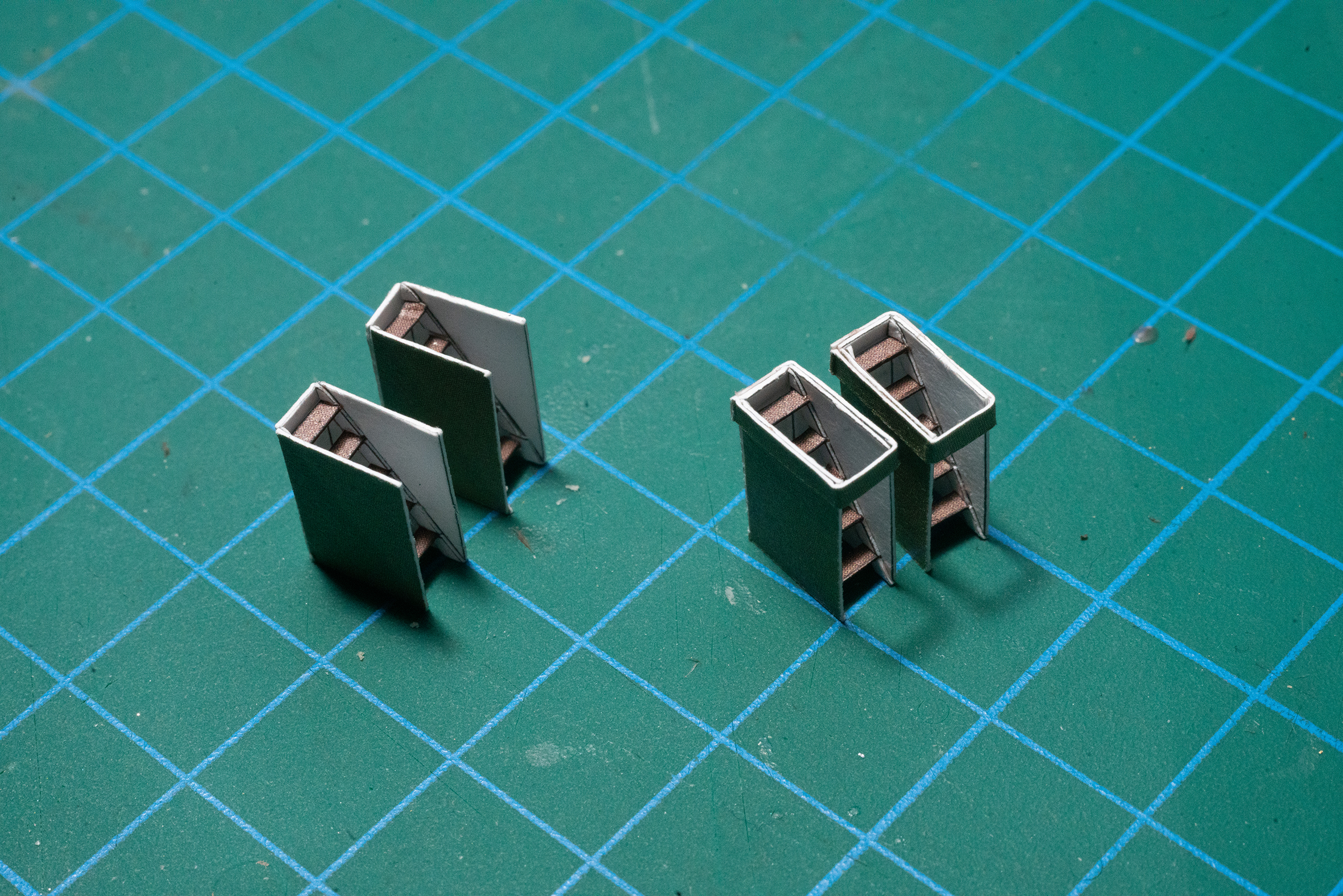
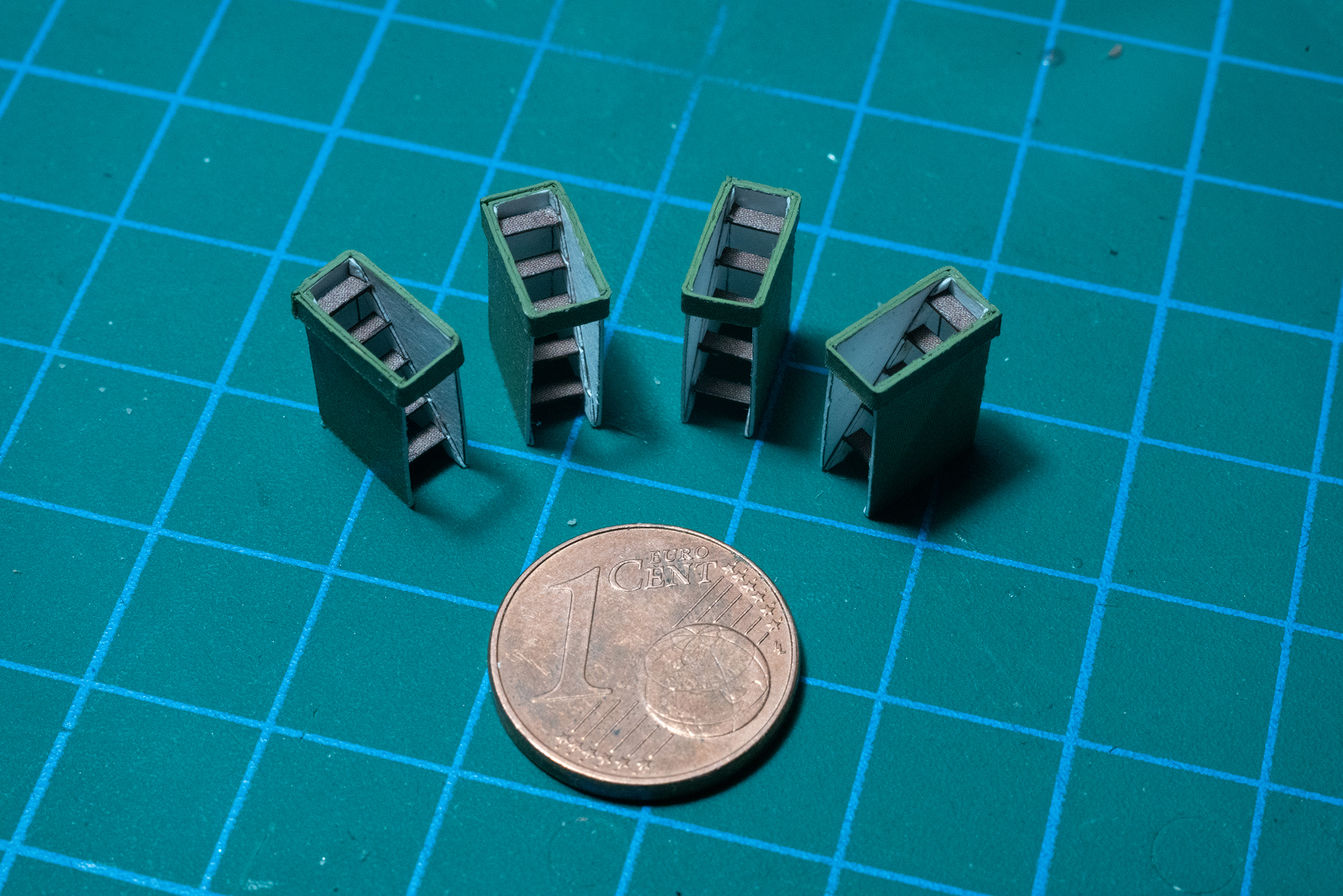
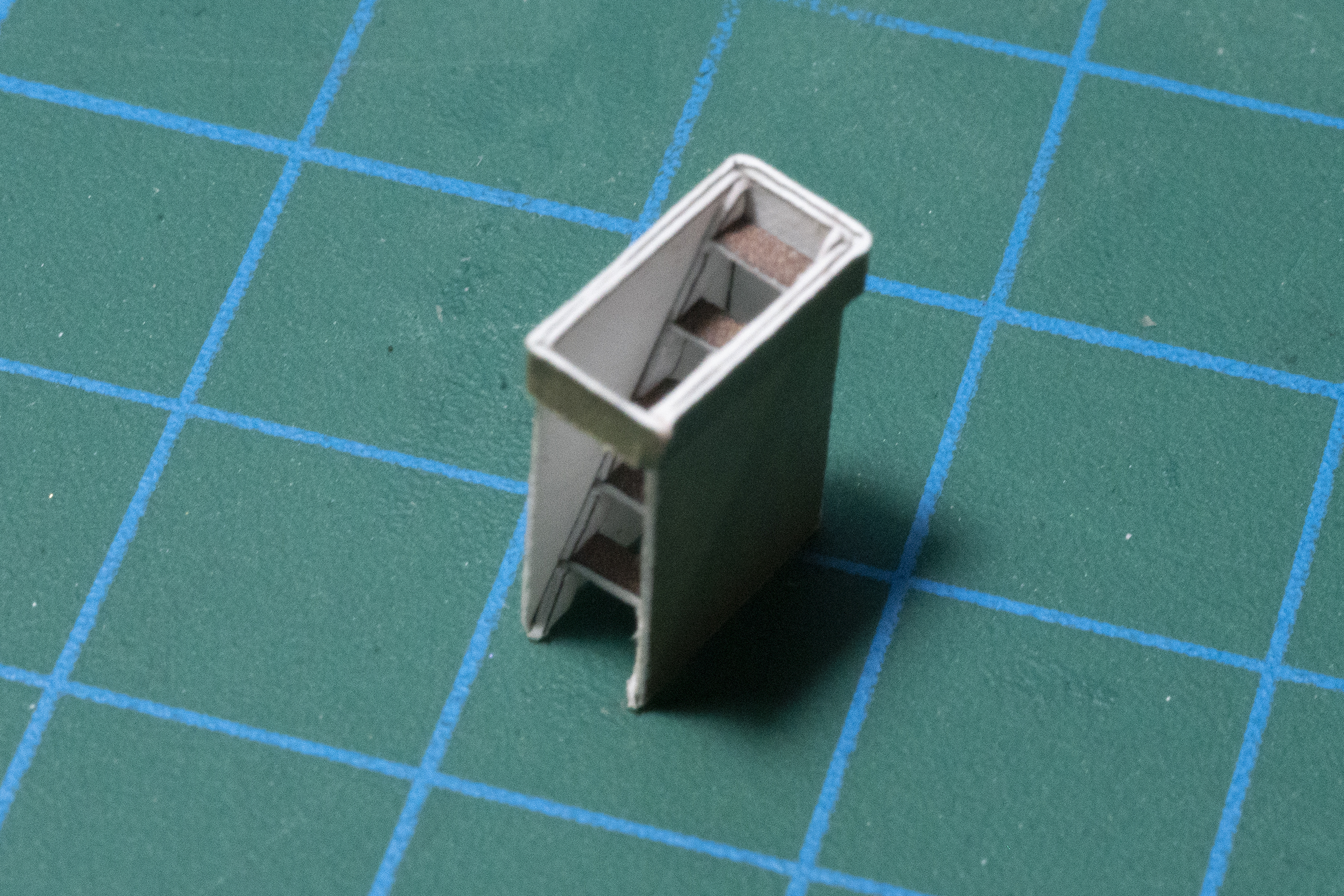
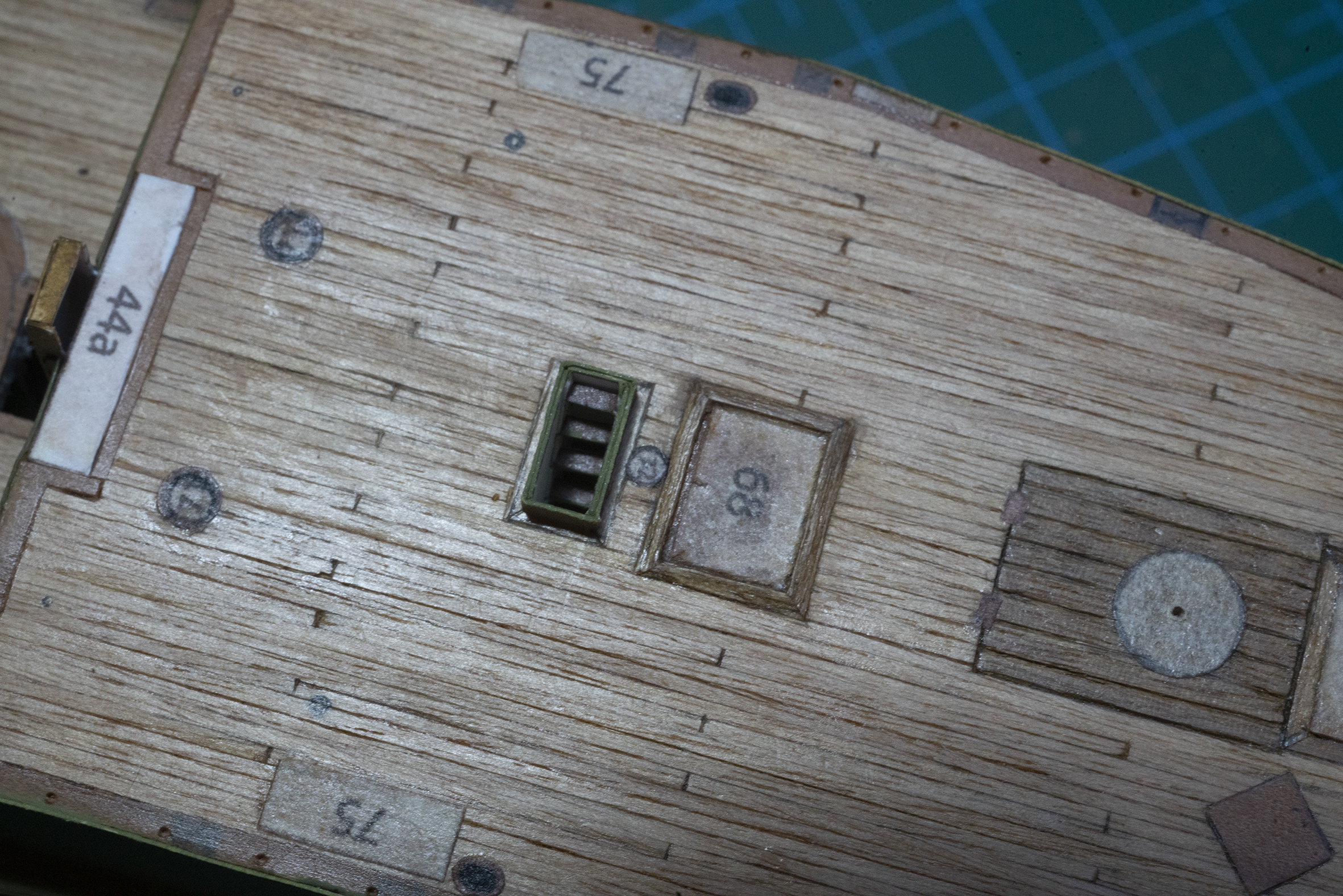
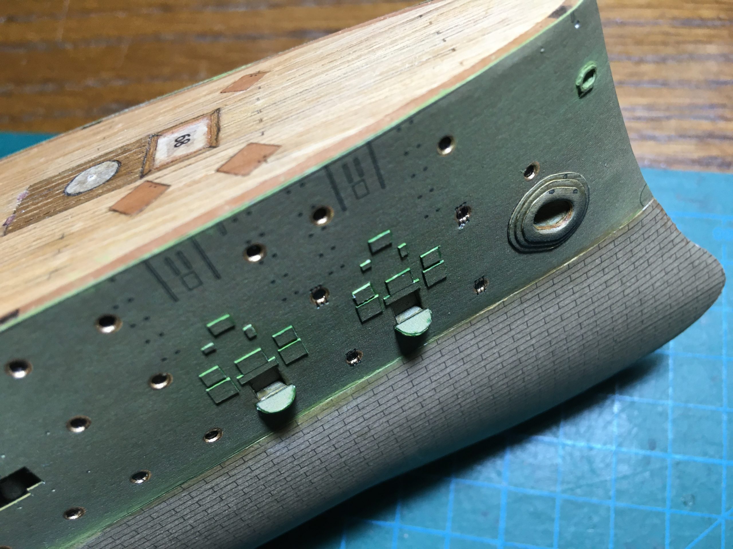
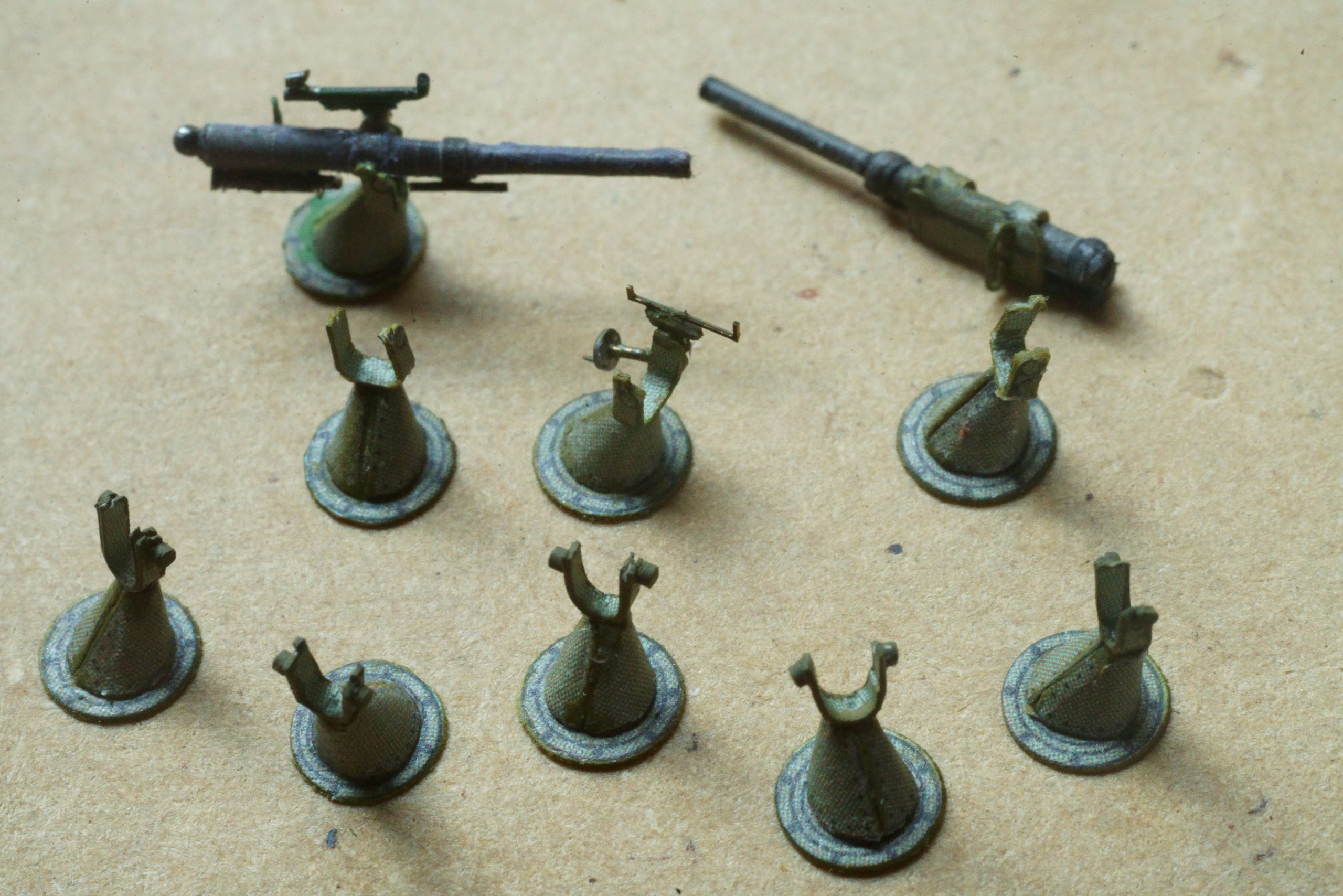
Here a later pic of work in progress on the Canet 75mm guns intended for inside the ship behind the hatches in the side. I am getting a bit of practice in for the ‘proper’ ones which will be on full display for the upper deck. Note the change in shape of the cradle for the barrel in the bottom picture, being closer to the archive photo of the gun above … Here unmounted and the edges unpainted.

Lots of detail to refine before I will be satisfied for the guns that will be fully visible on deck! 🙂

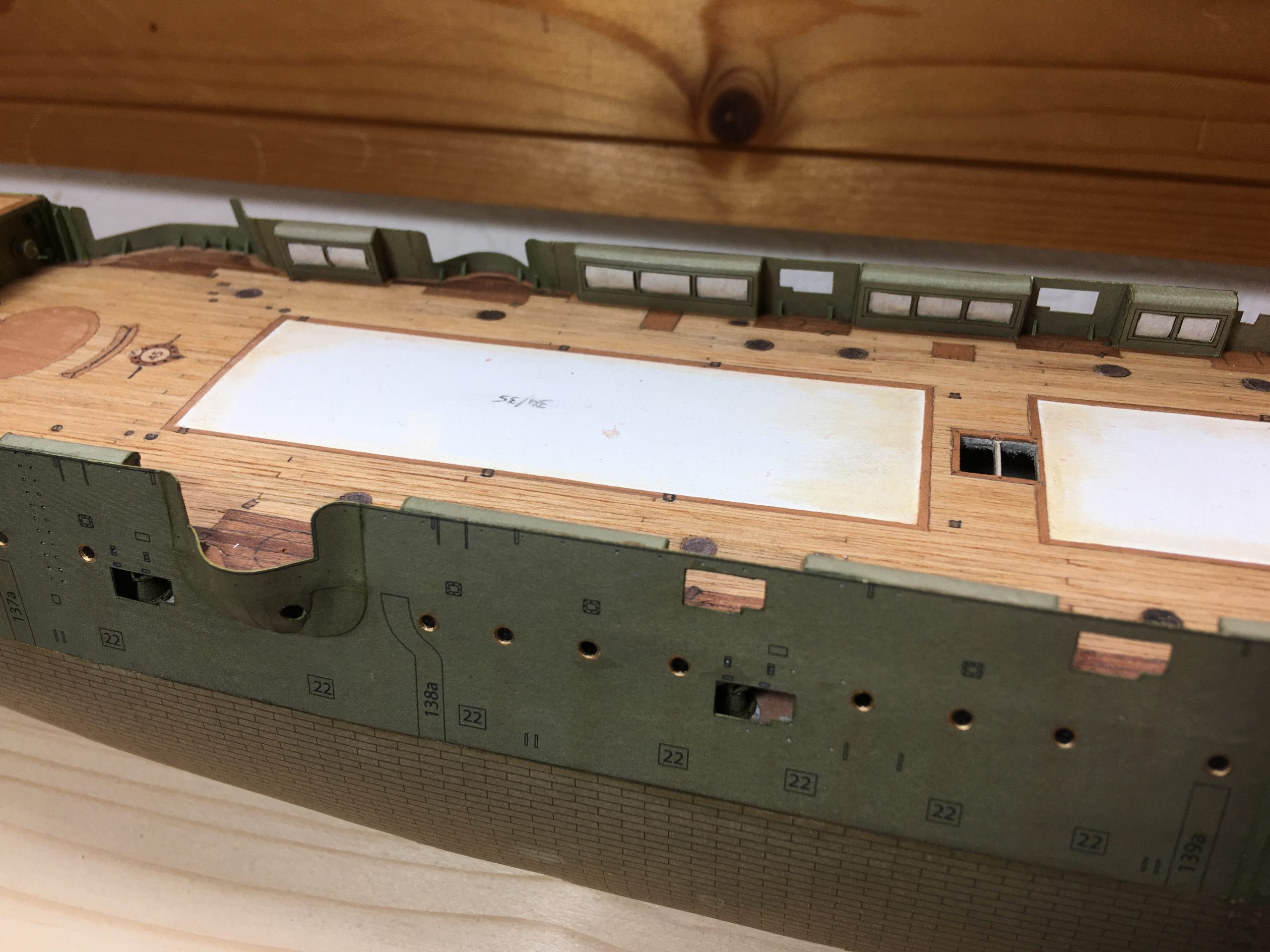
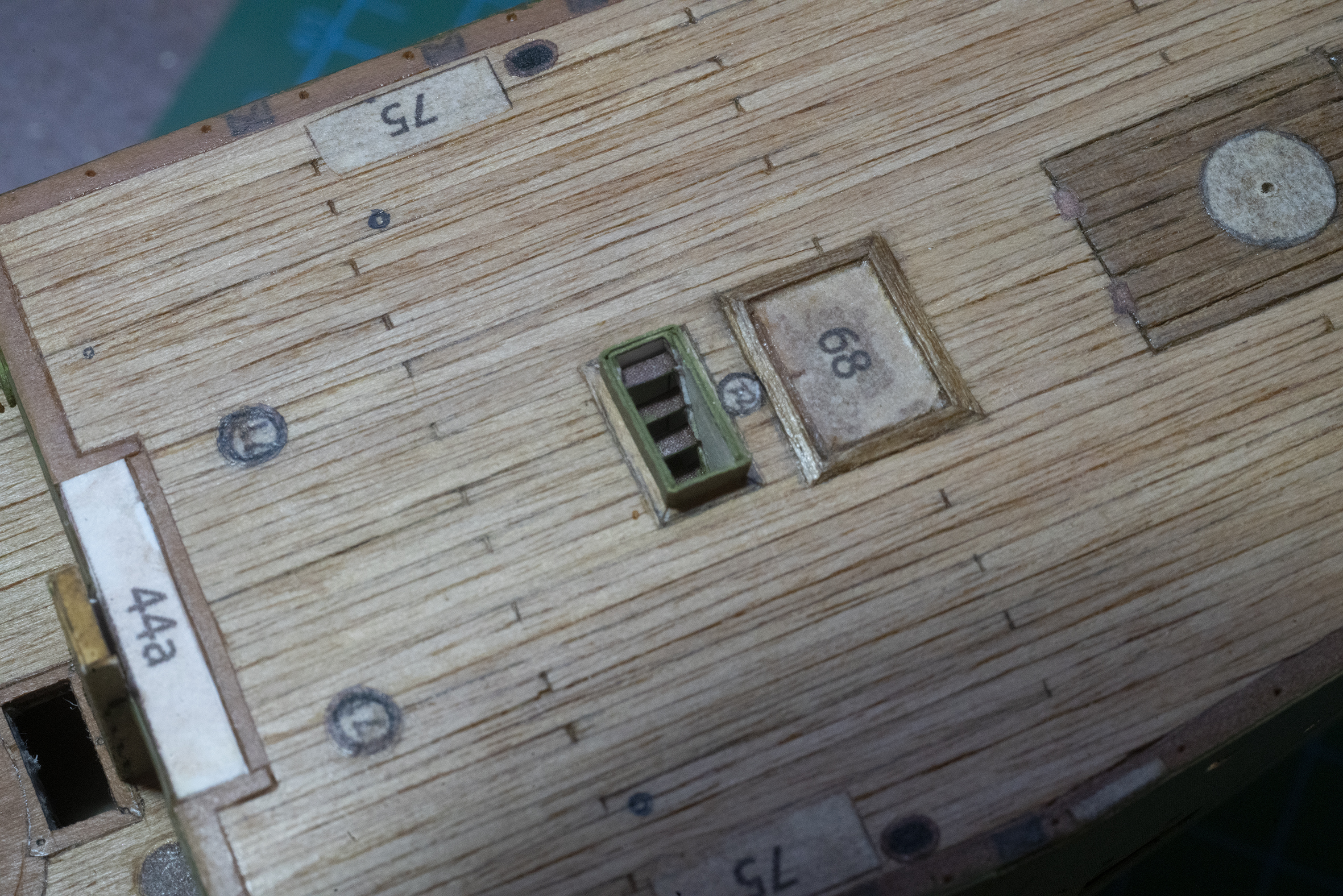
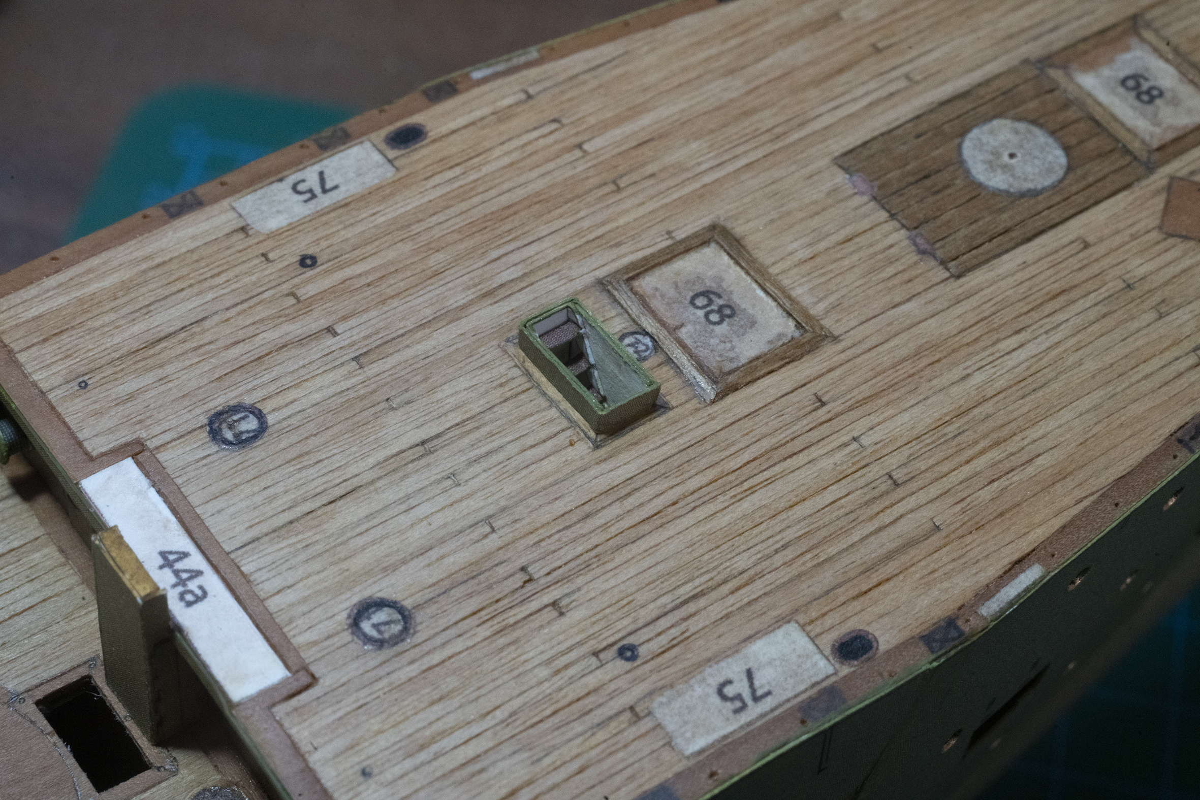
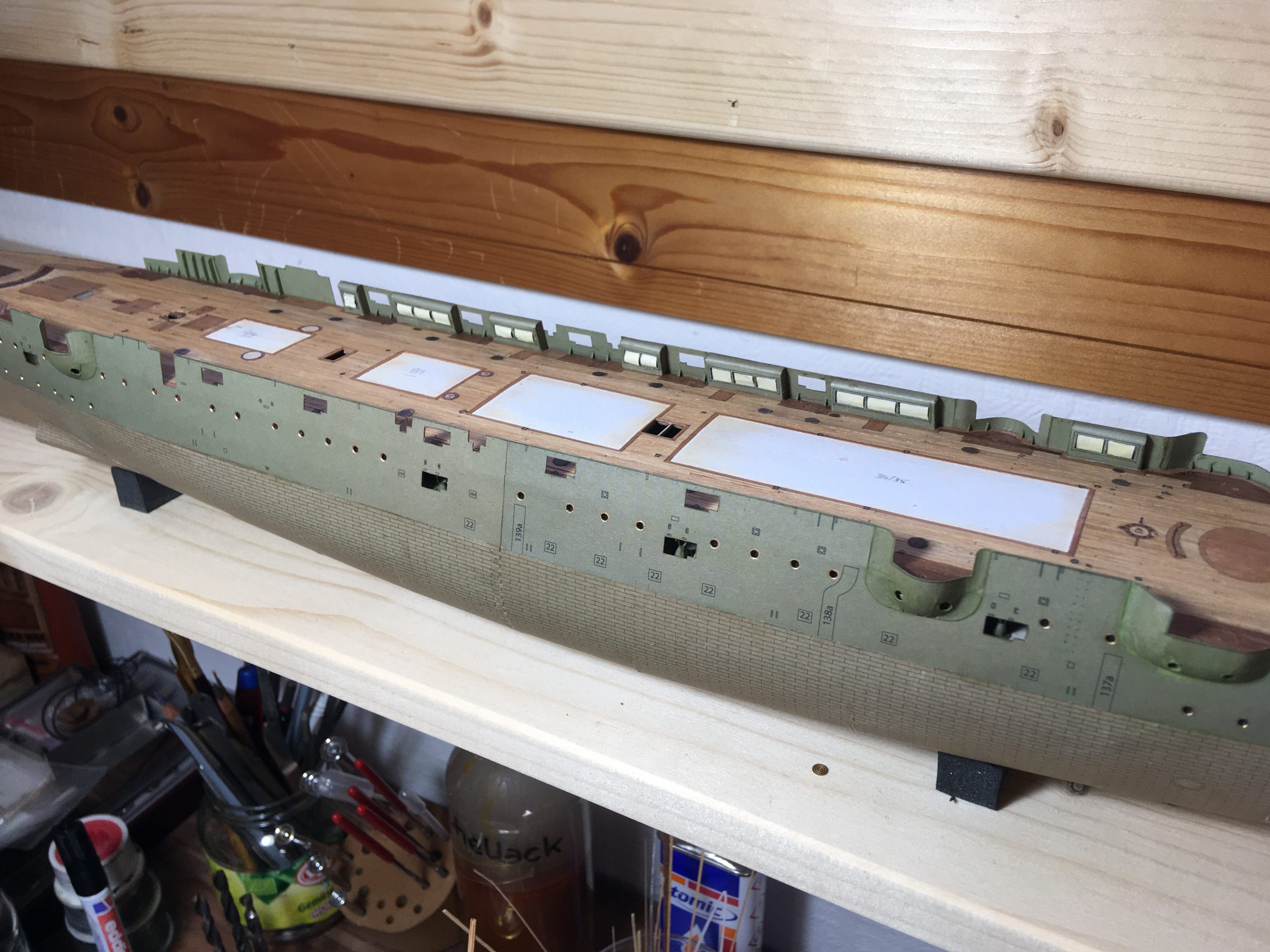
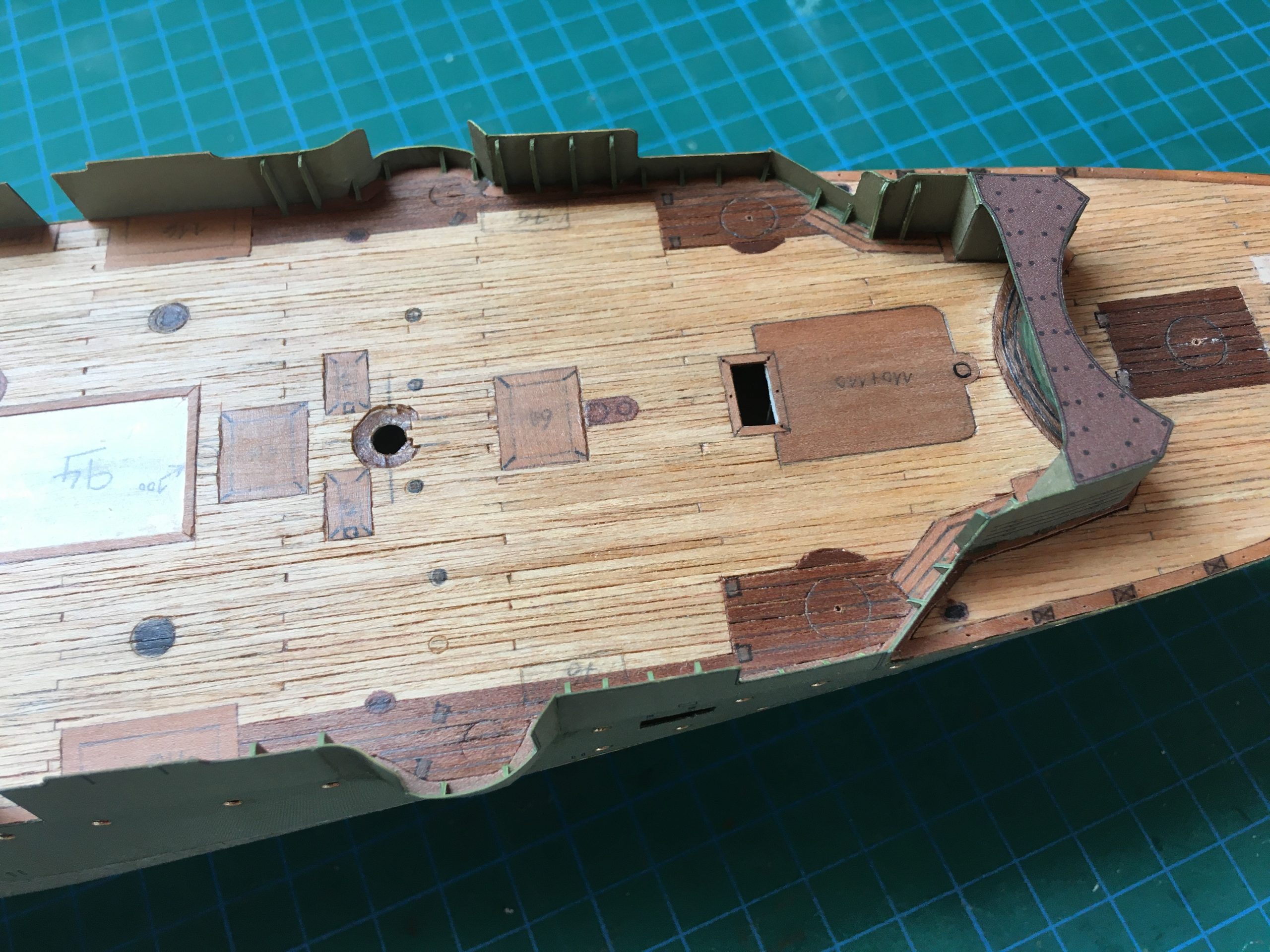
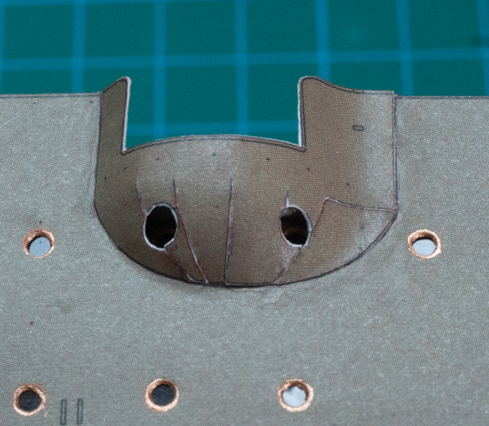
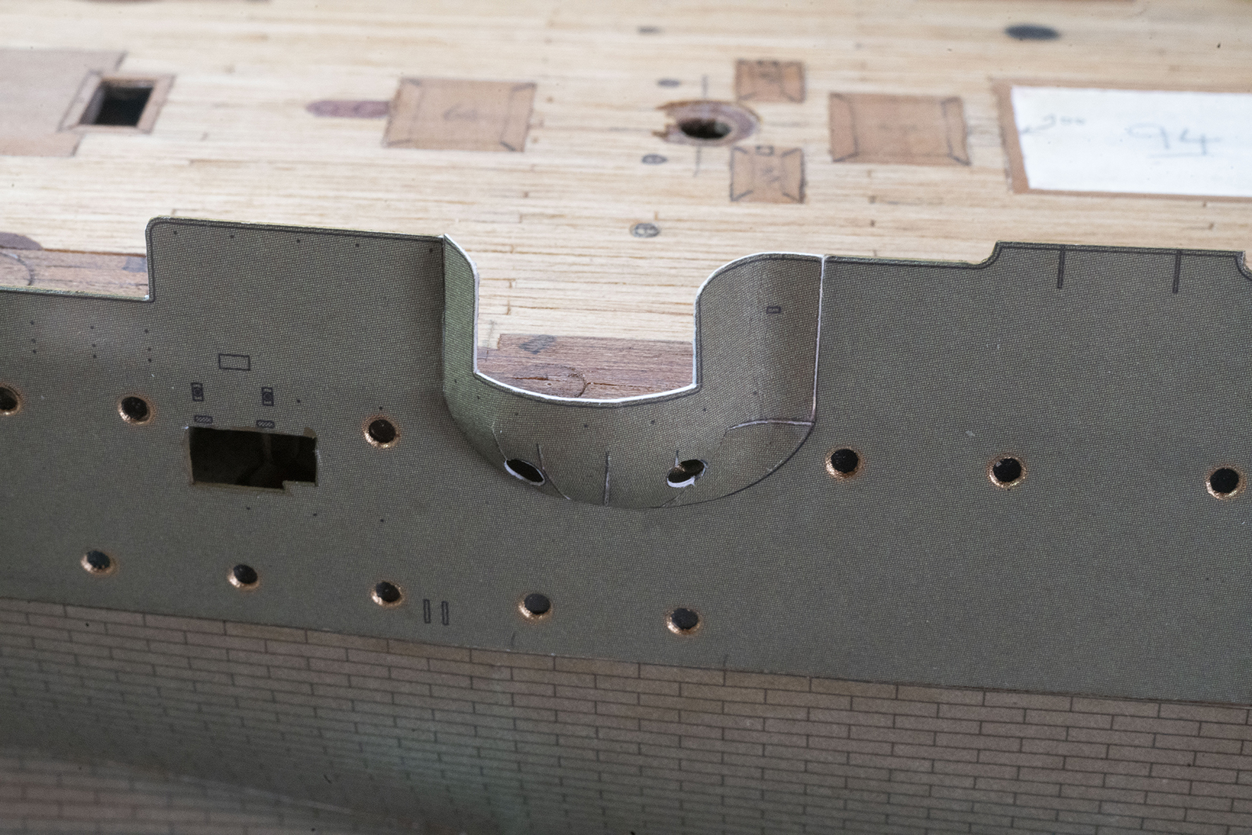
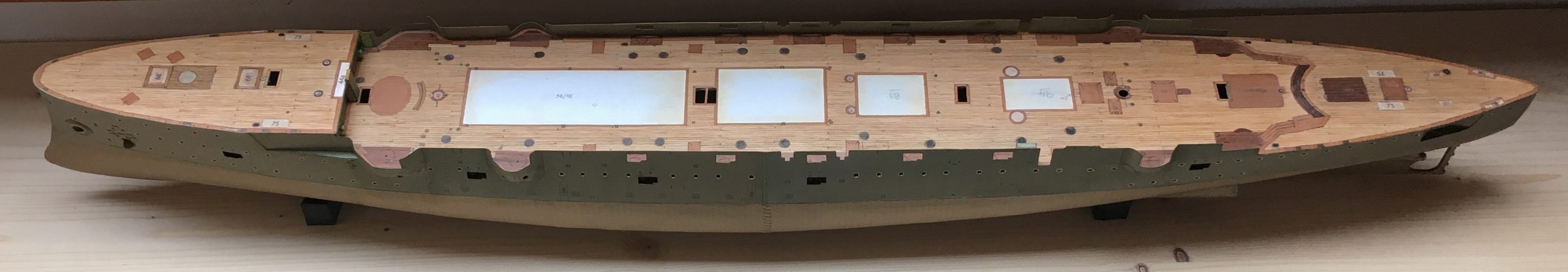
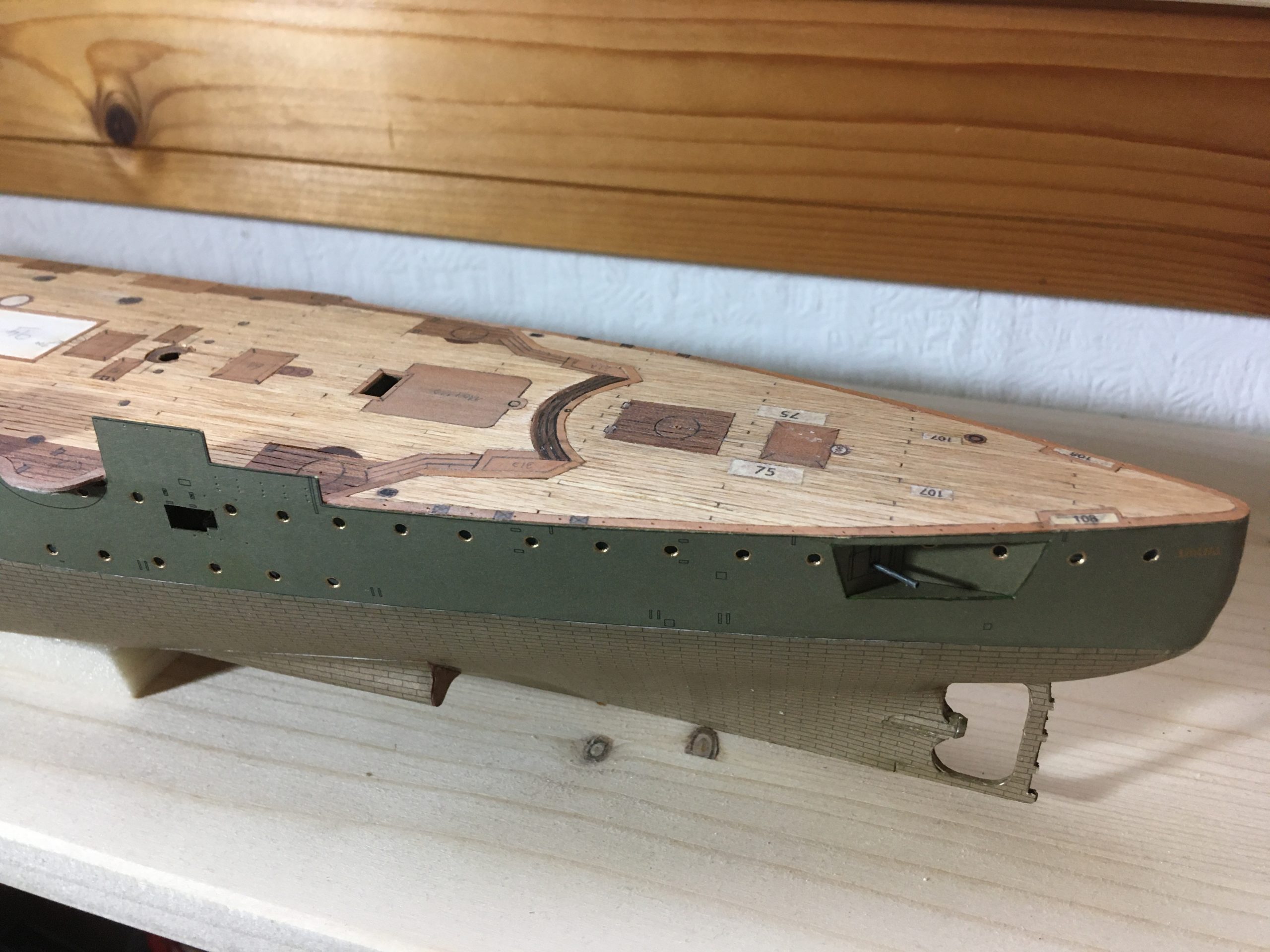
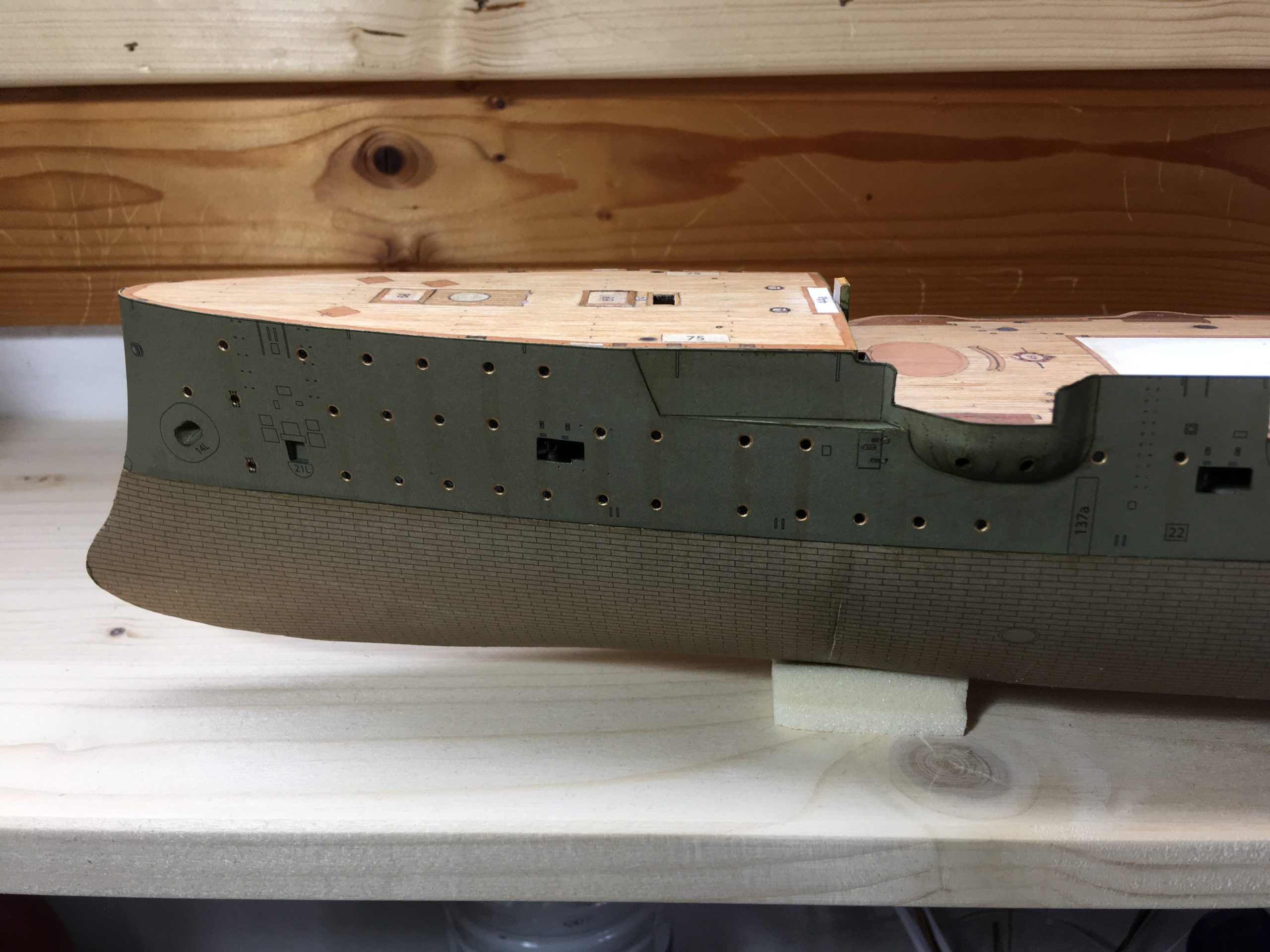
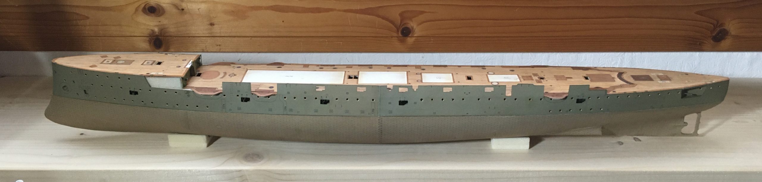
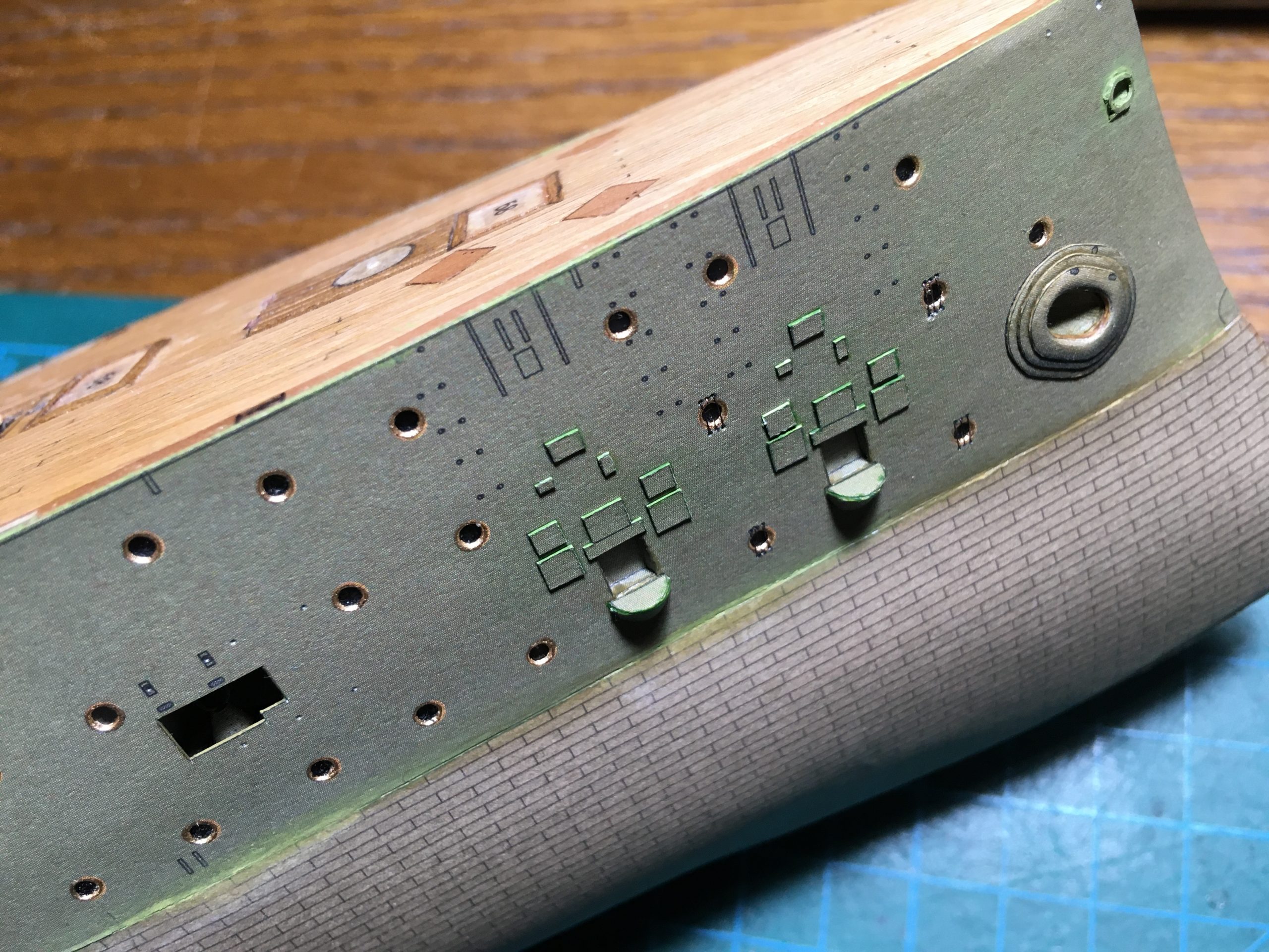
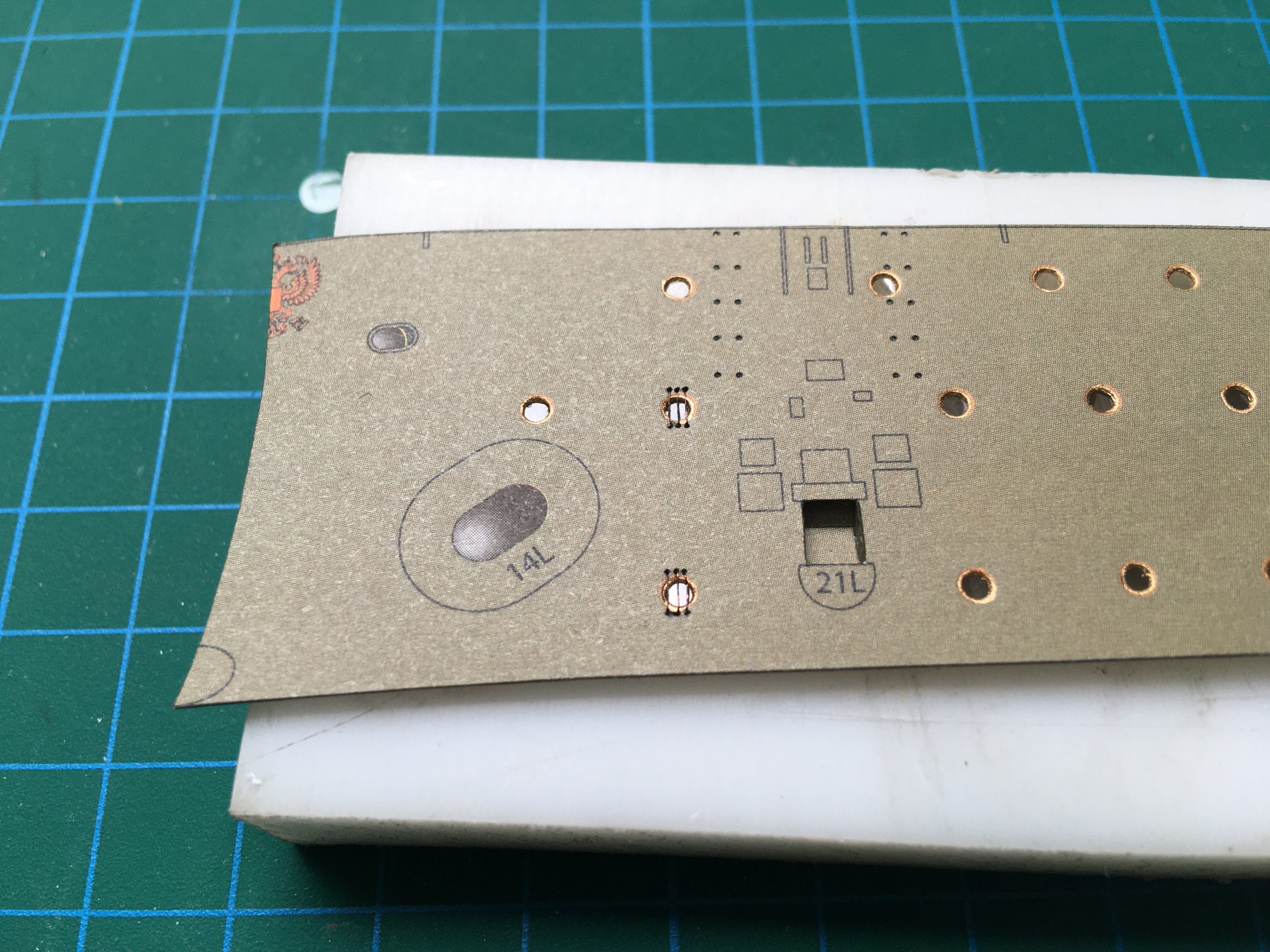
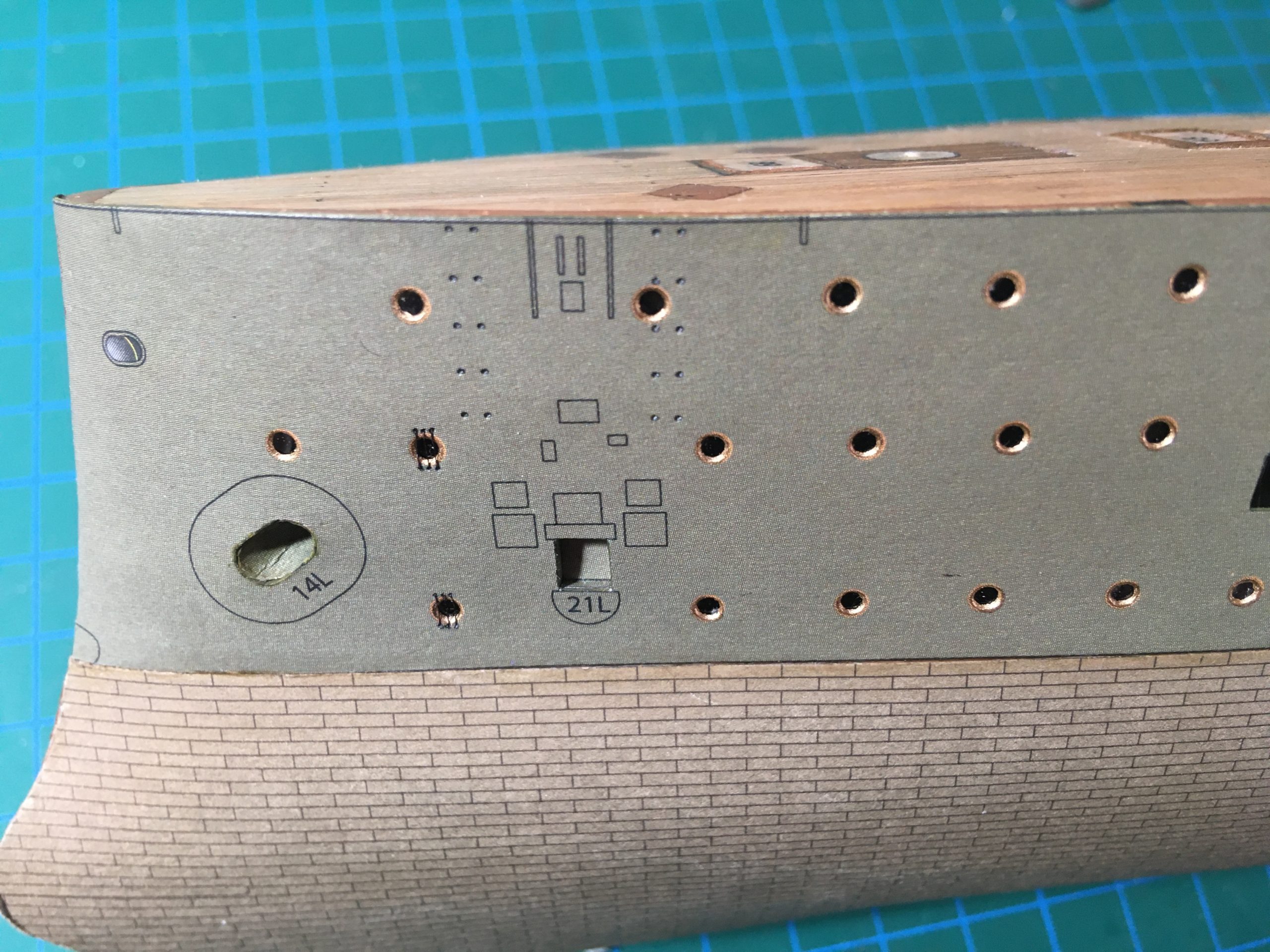
So, the hull sides also have to have quite a bit of work done on them before fitting to the carcass: The gun recesses at the aft and the recess behind each anchor, for example. There are various other jobs in sight. I want to cut out the portholes and ‘glaze’ them. I was going to fit brass surrounds, but they are a bit garish, so I opted for gold paint instead 🙂

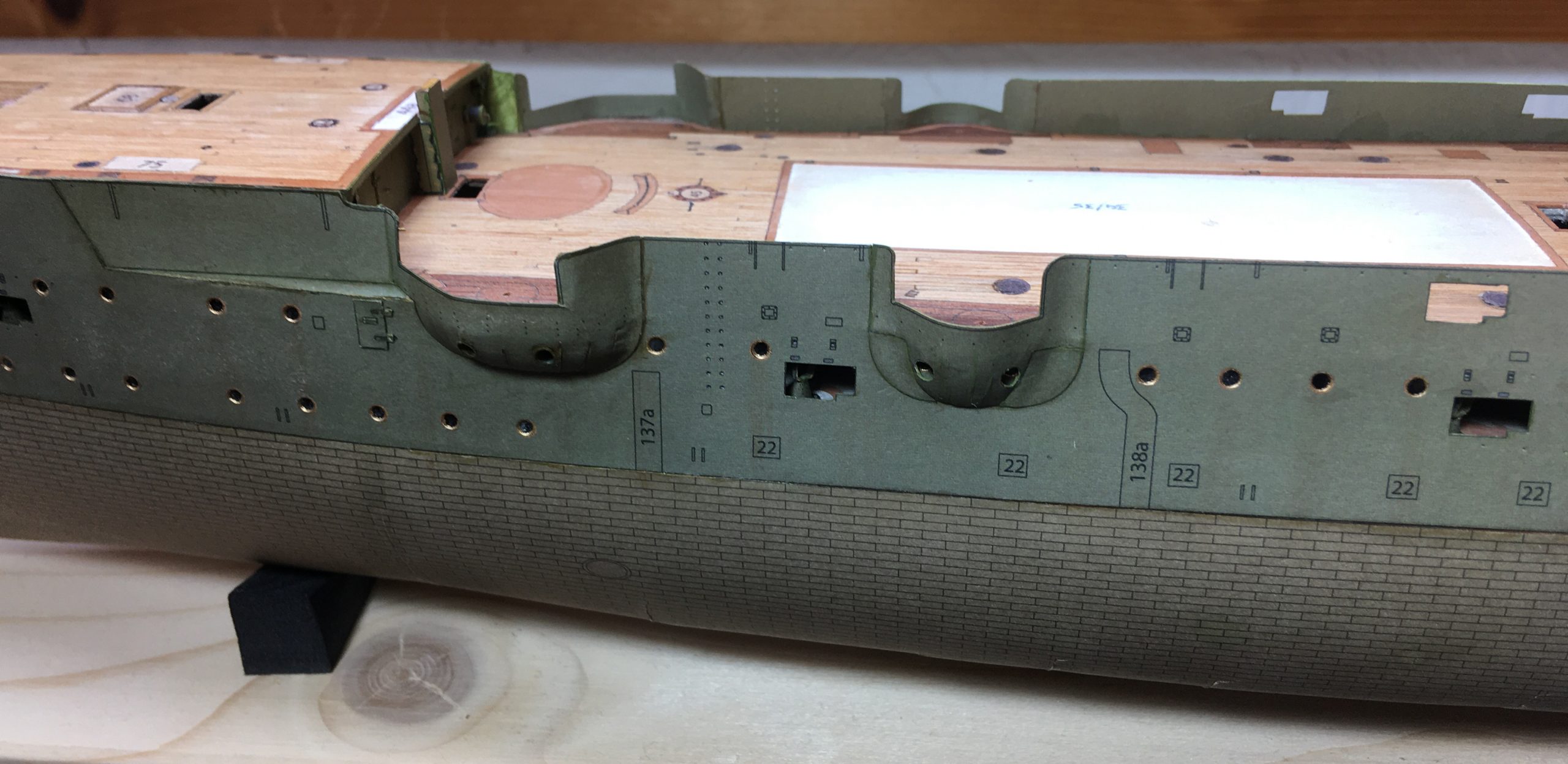
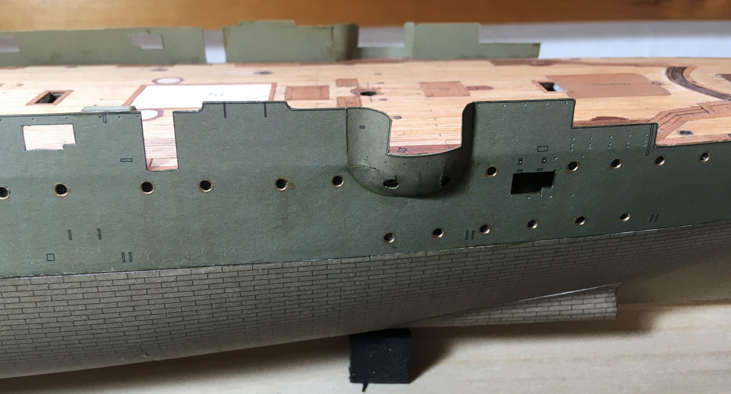
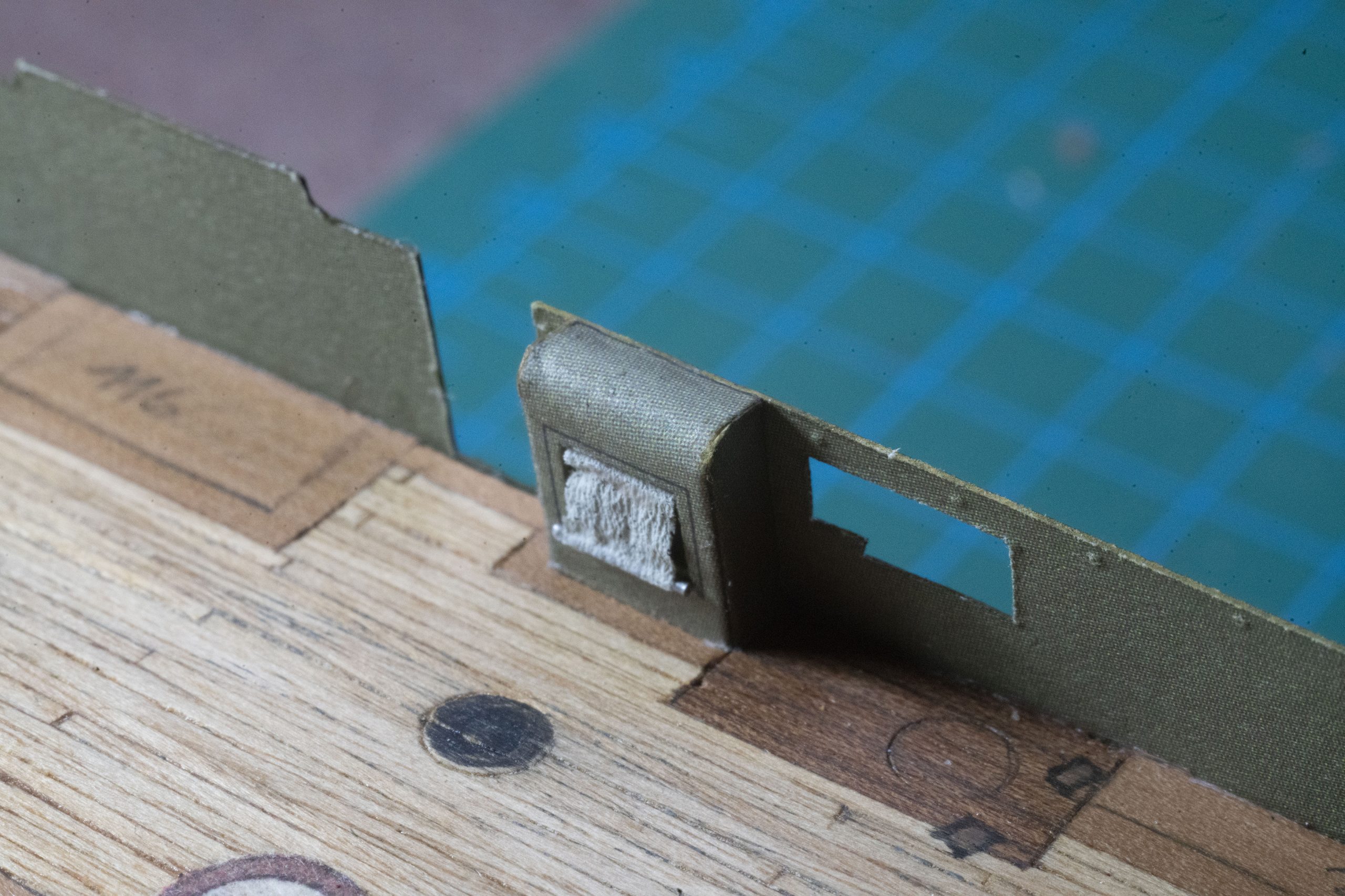
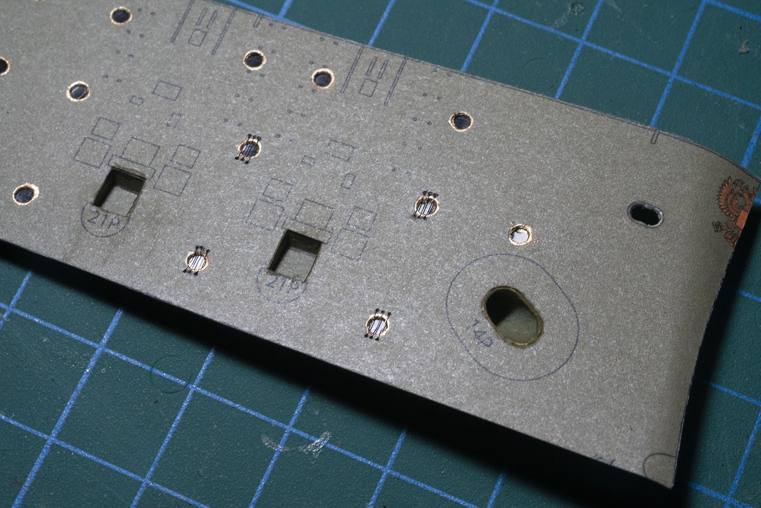
There are a pair of portholes for each anchor which have bars over them…

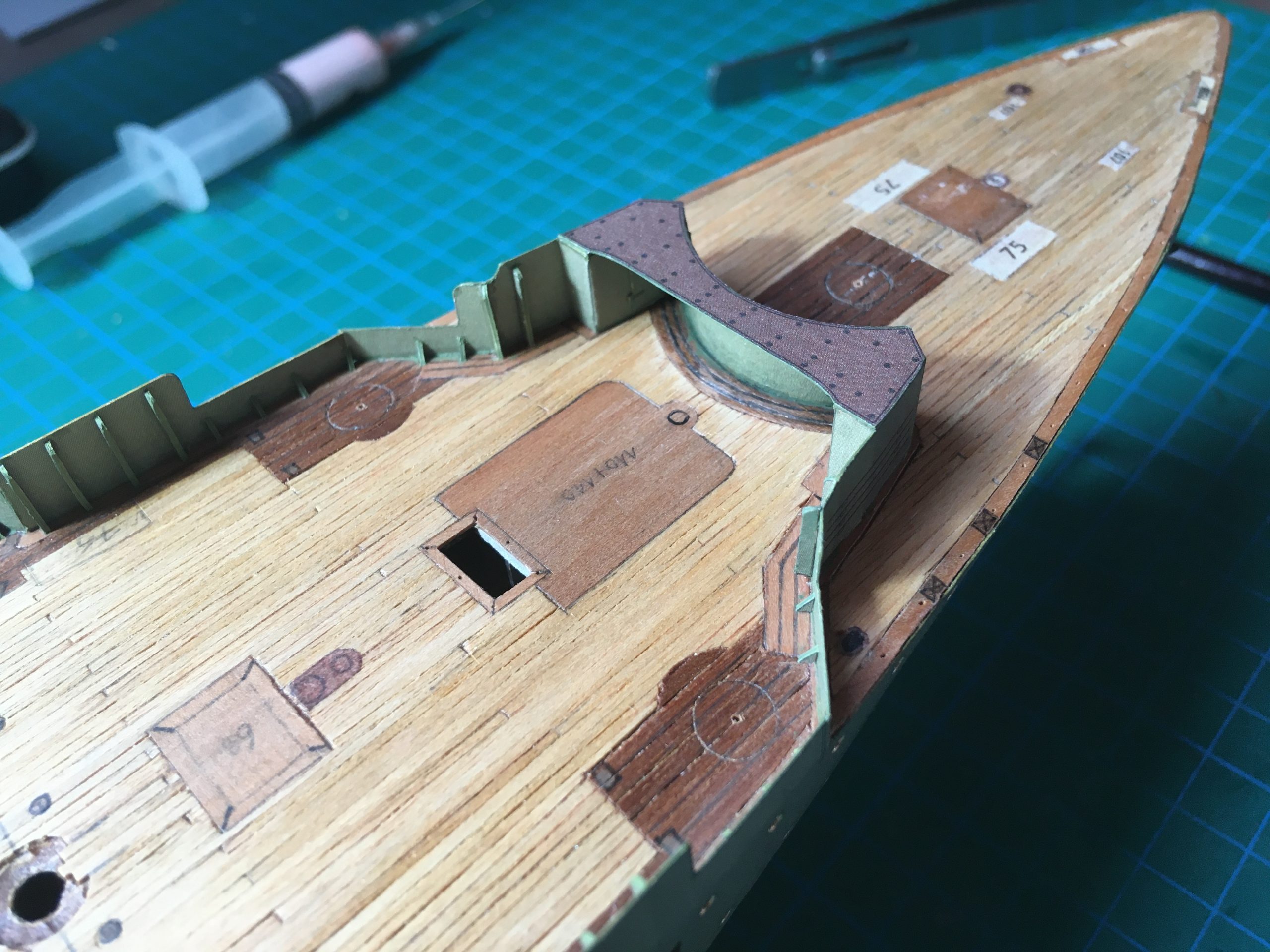
… Which I made from 0.1mm copper wire stripped out of some electrical leads and blackened with a permanent marker. Holes were pierced in the card with a sharpened needle and the wires threaded through, pulled taut and glued from the back, same as was done for the ‘risers’ for the hatches for the aft most gun, seen below on the right.


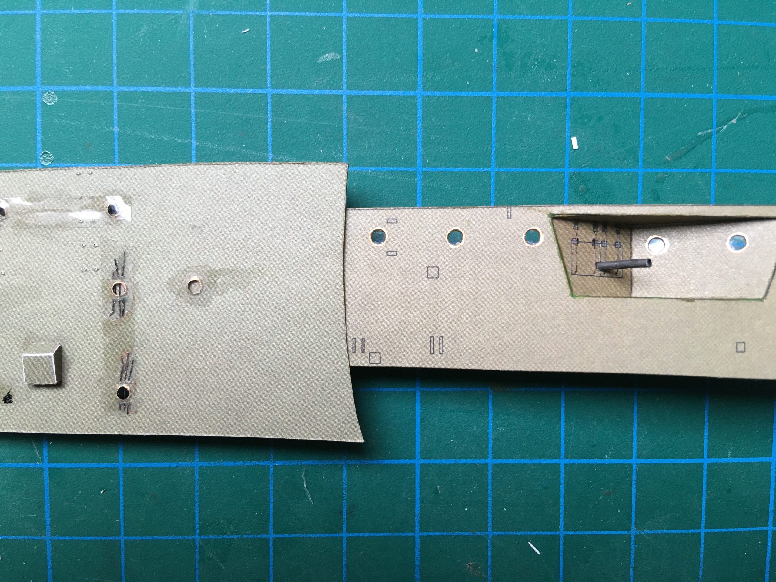
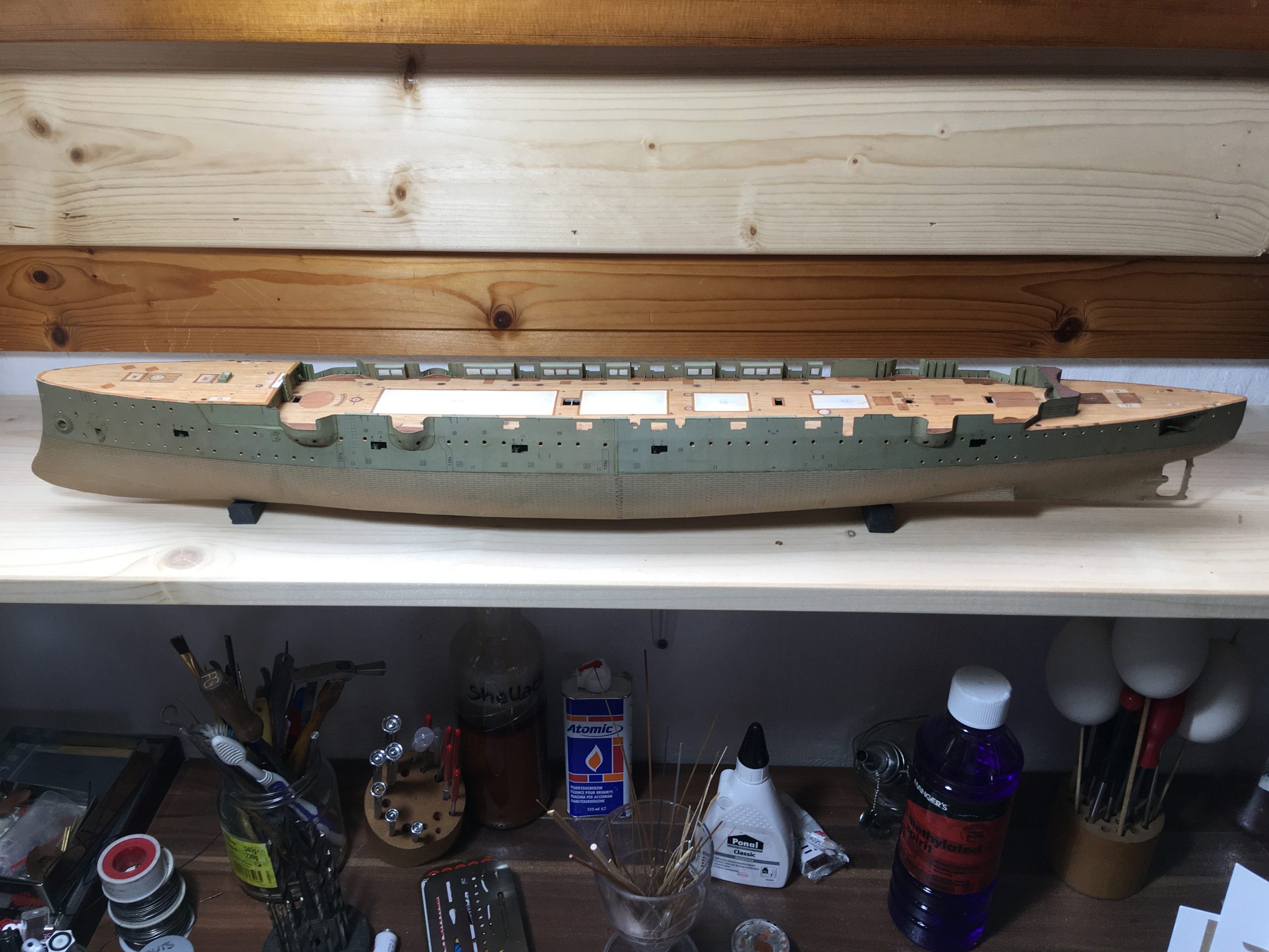
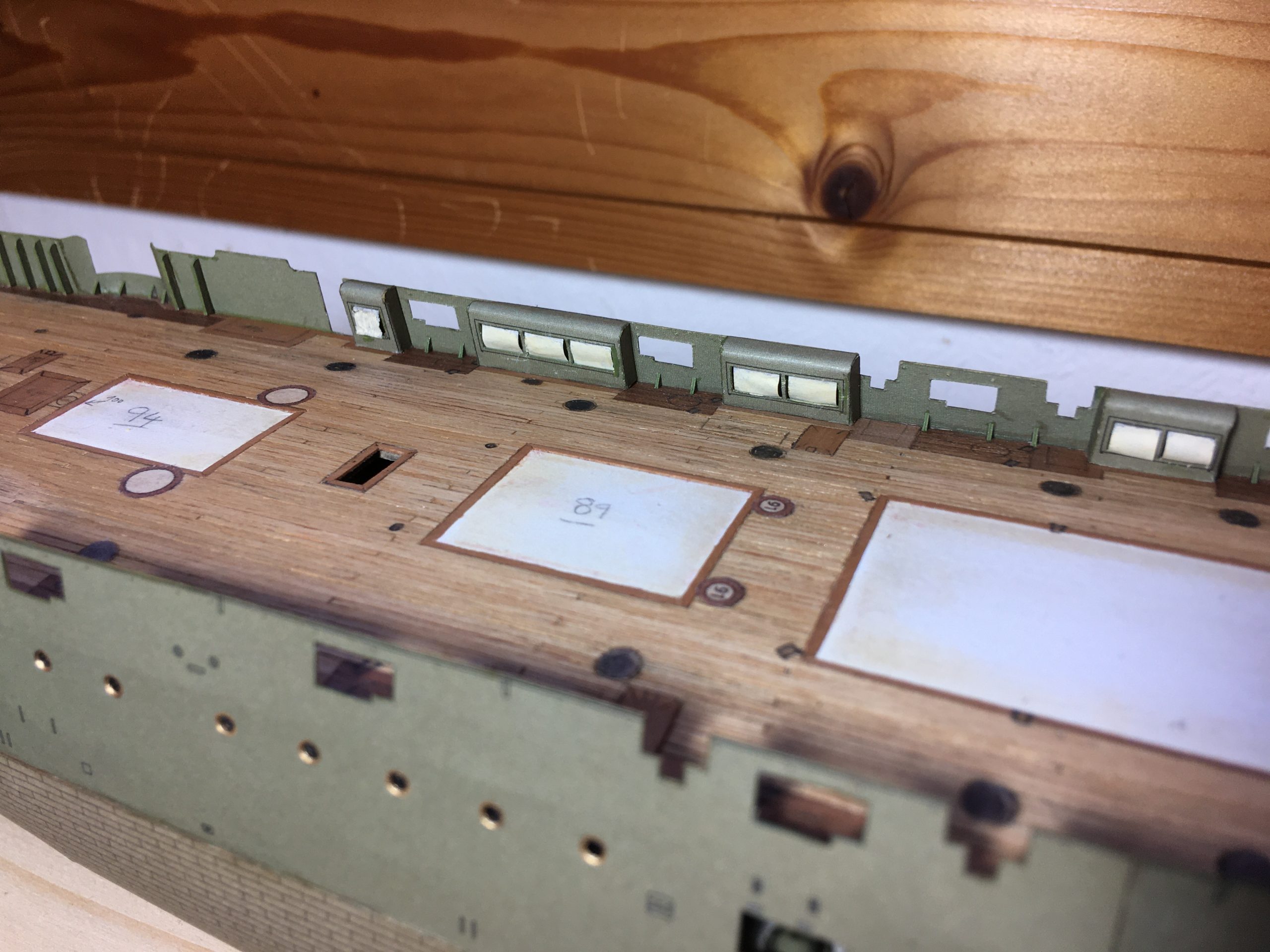
Here are the mid ships gun mounts positioned in their places in the port hull , prior to fitting the sides. I put them in now, as they wouldn’t fit through the hatches afterwards. I don’t want to fit the barrels yet, as they would make the fitting of the hull sides more difficult to do without damaging them. The black spots will end up behind where the portholes will be afterwards…

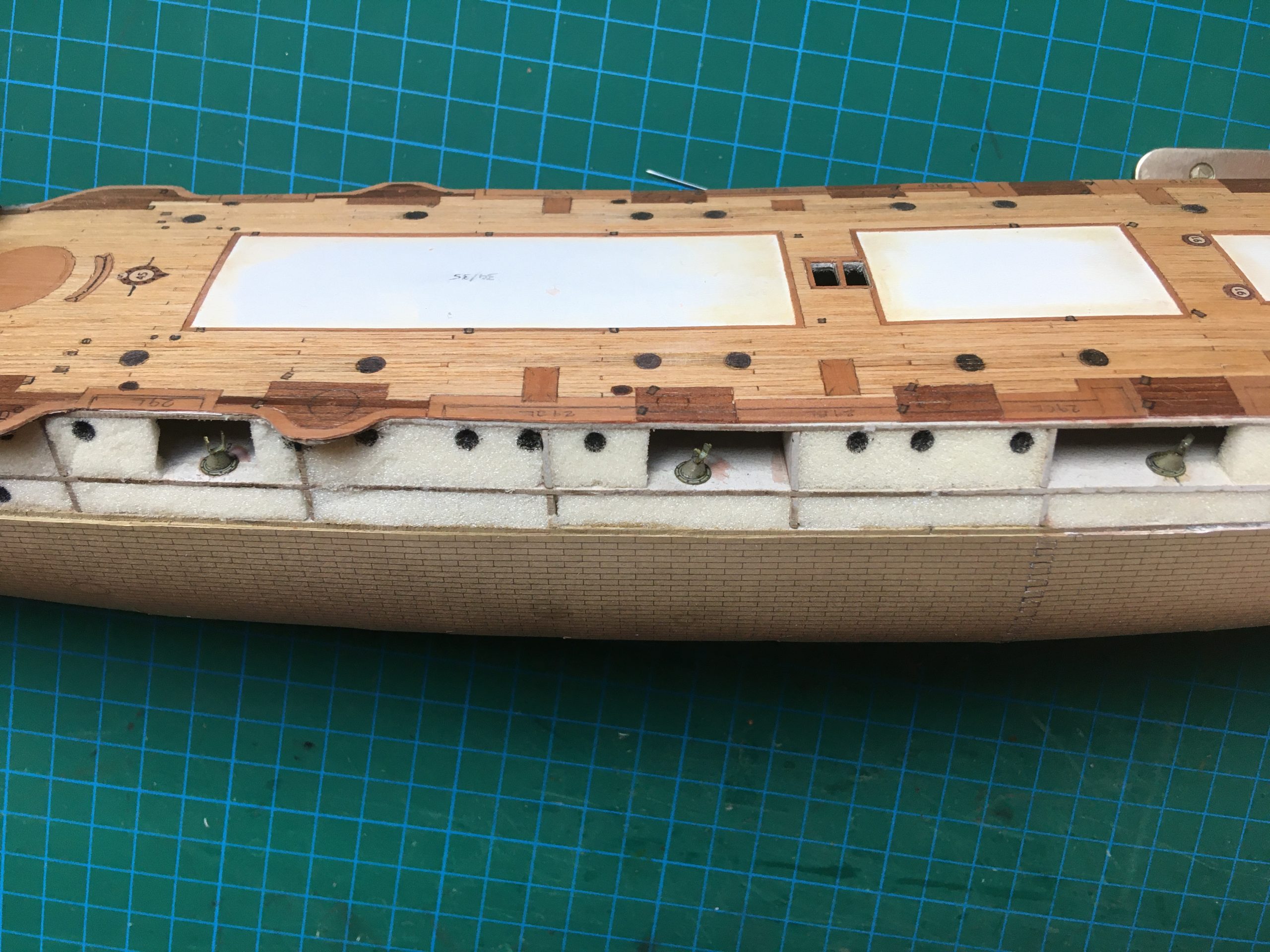
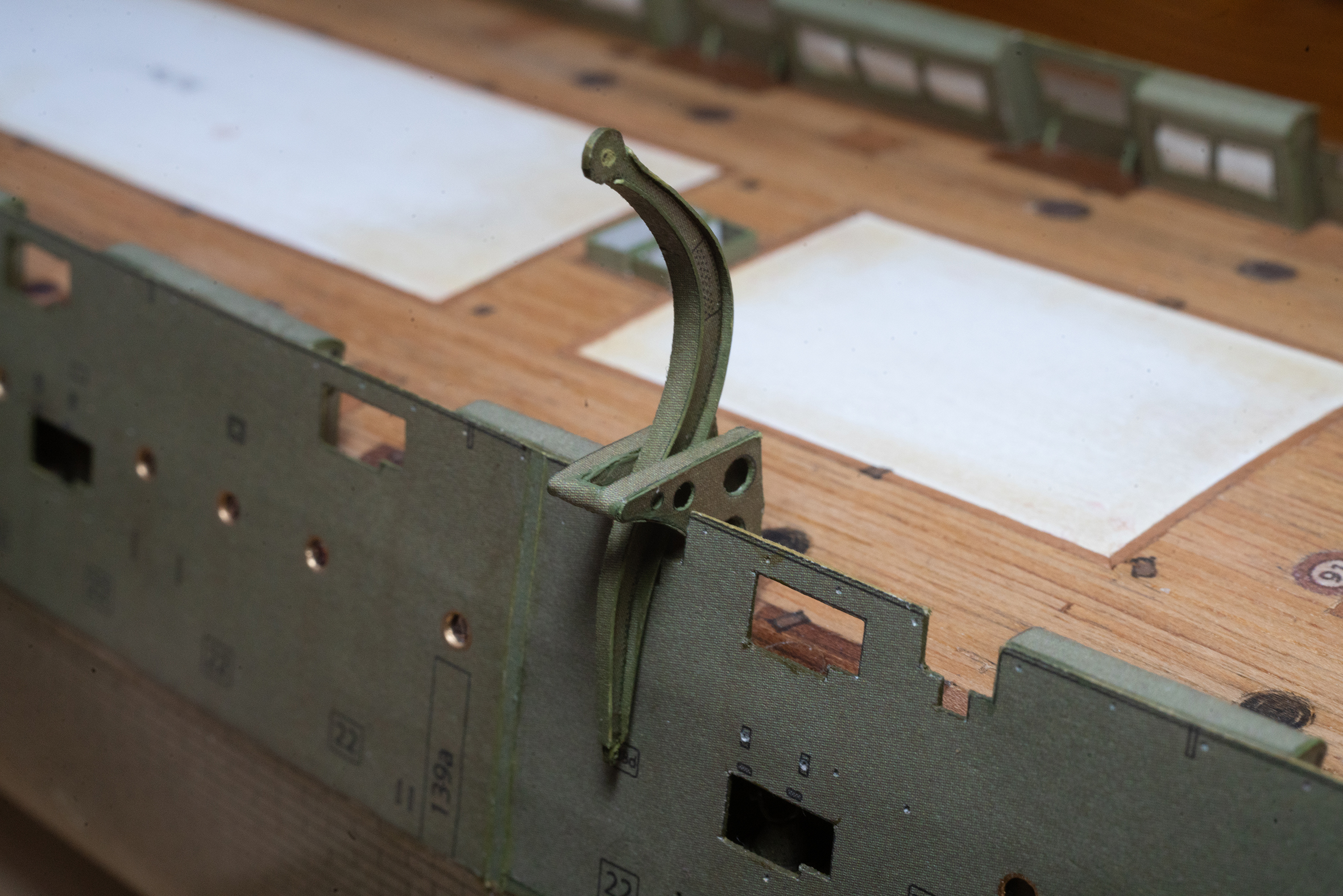
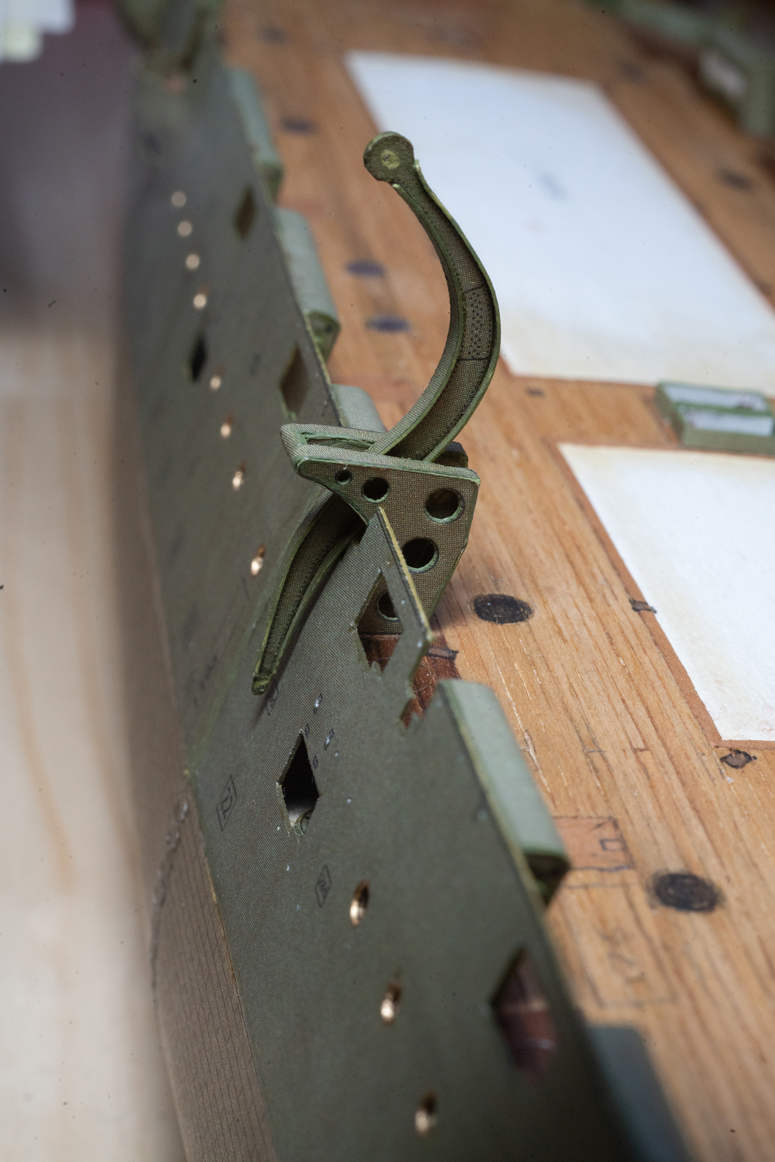
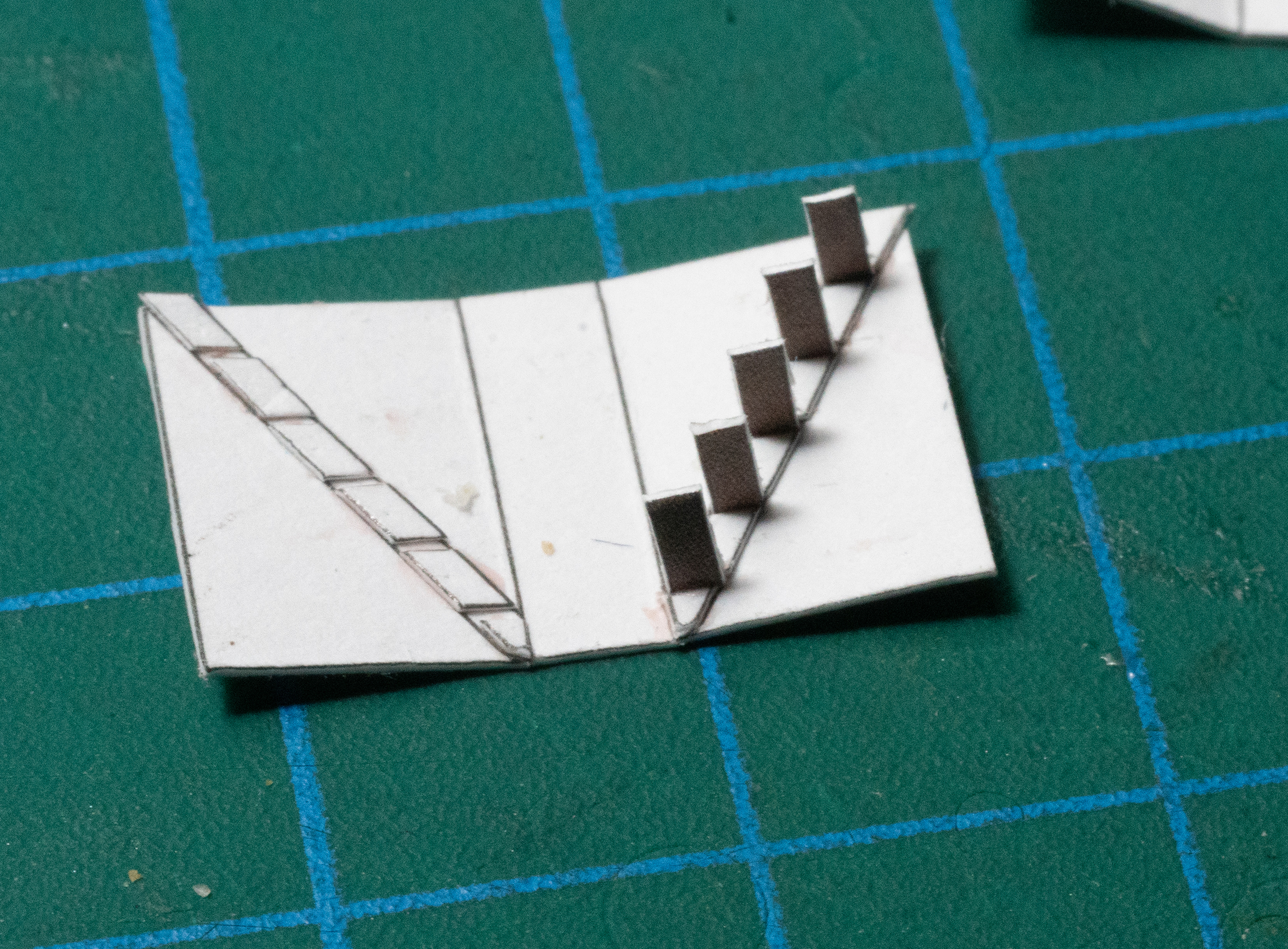
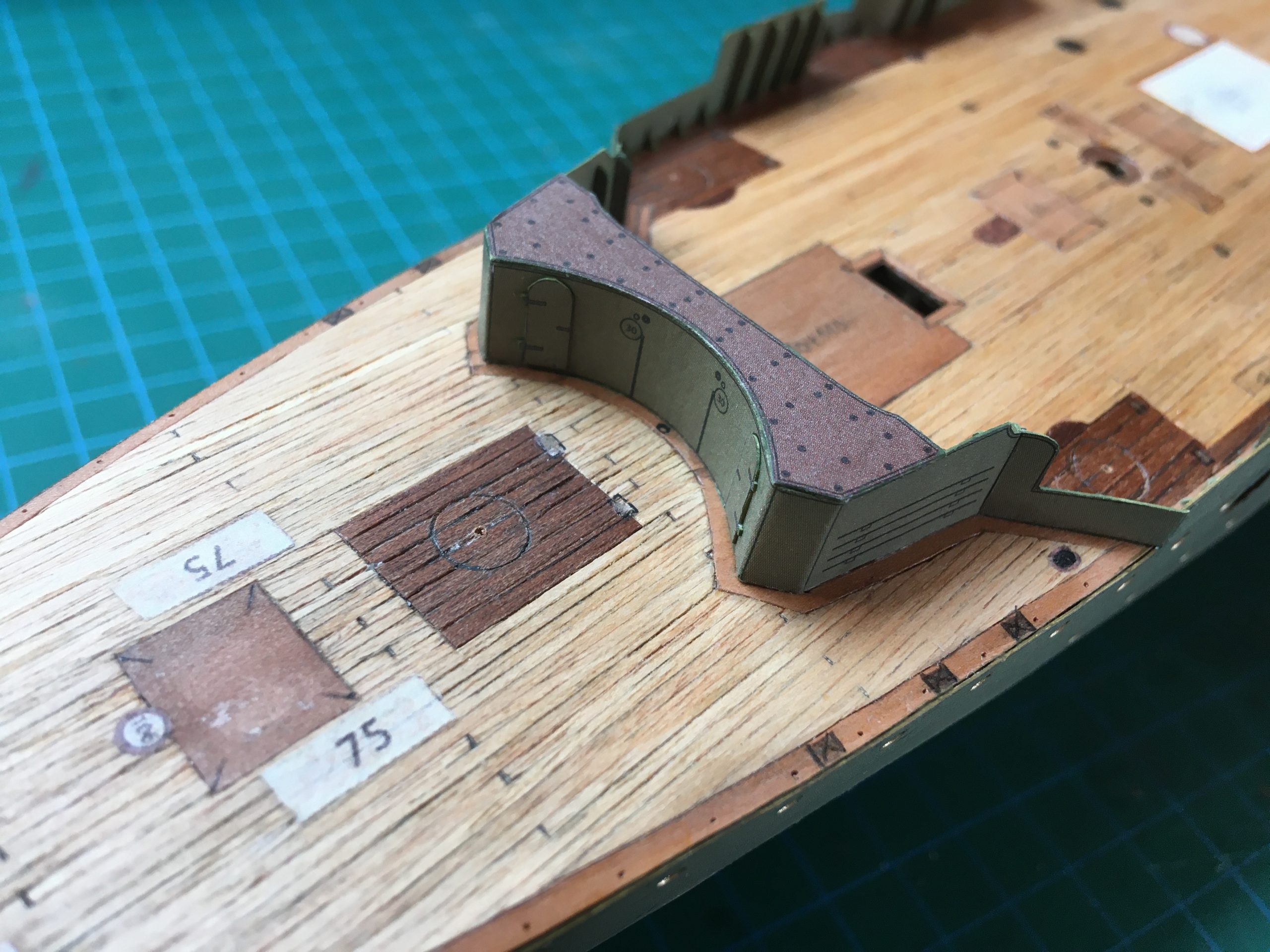
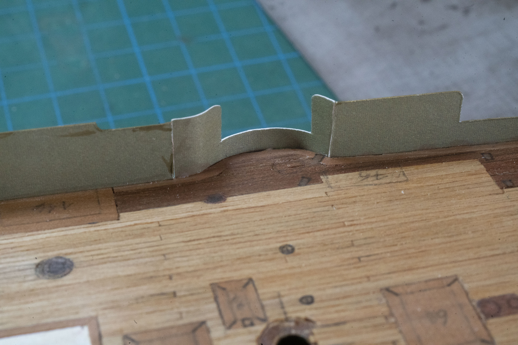
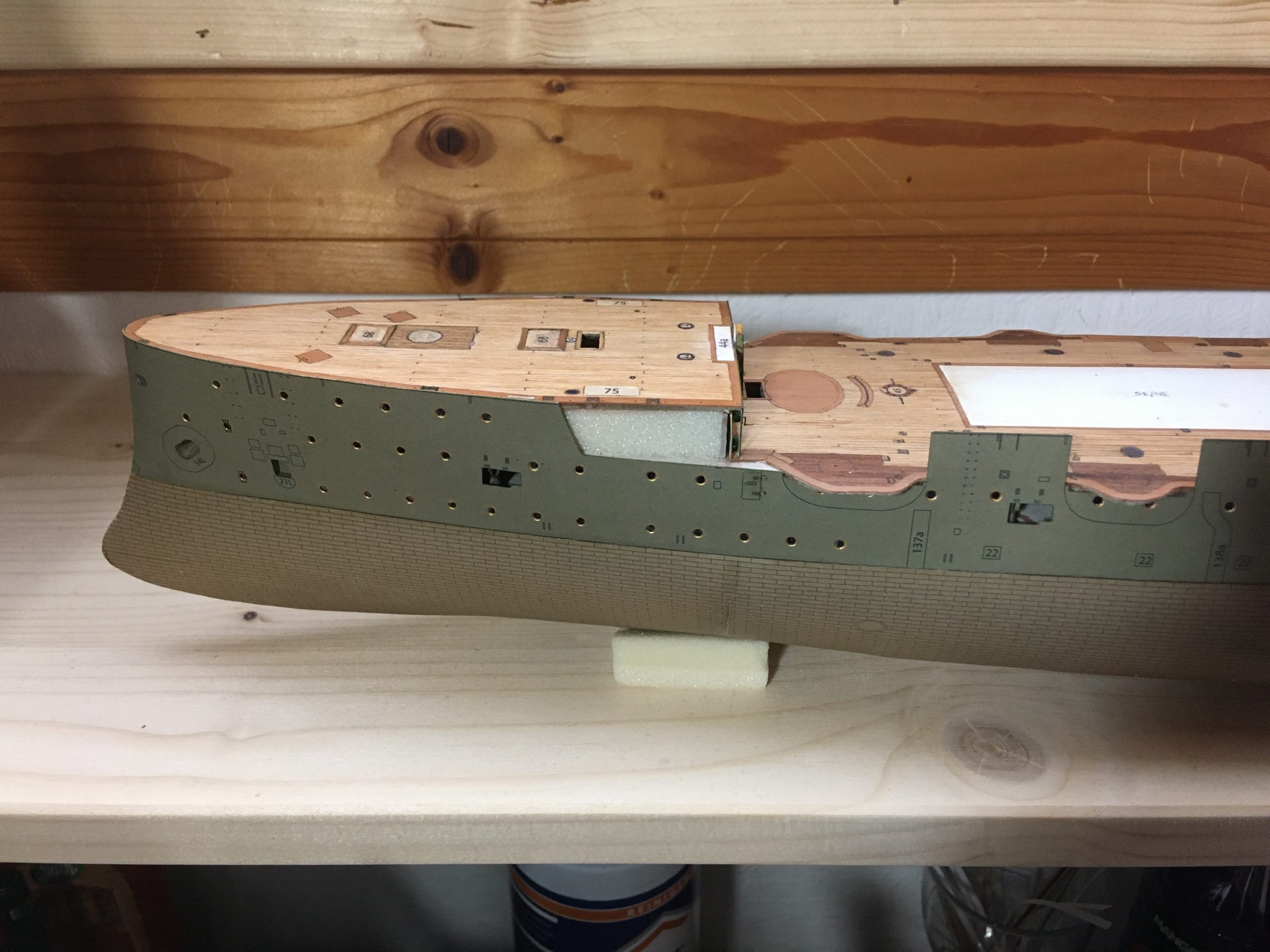
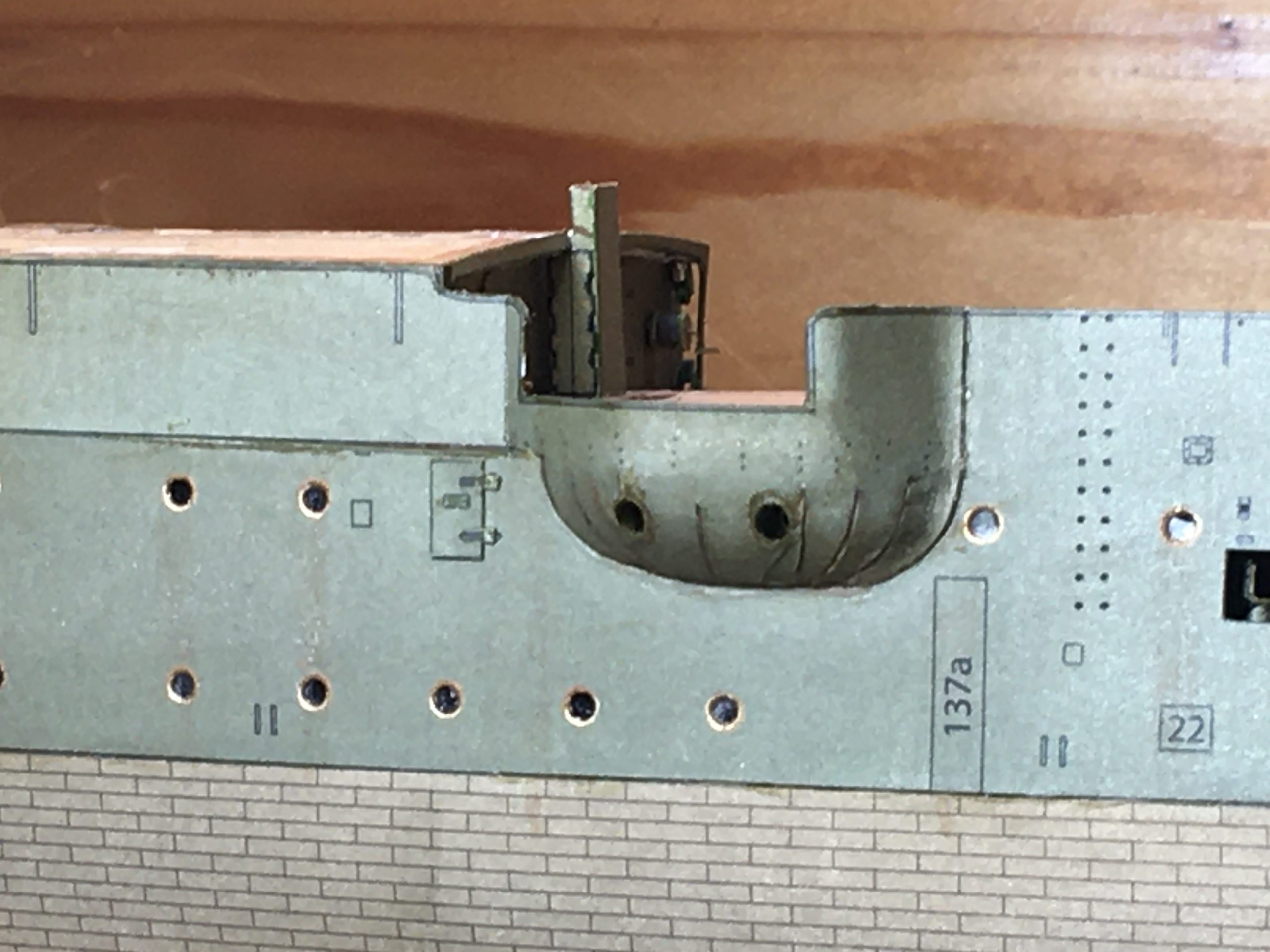
Another detail I decided to add is the Hawse pipe, as seen in the picture below: The Hawse hole on these ships is built up outside the hull and will be added later.


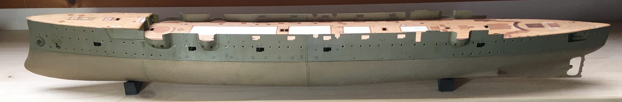
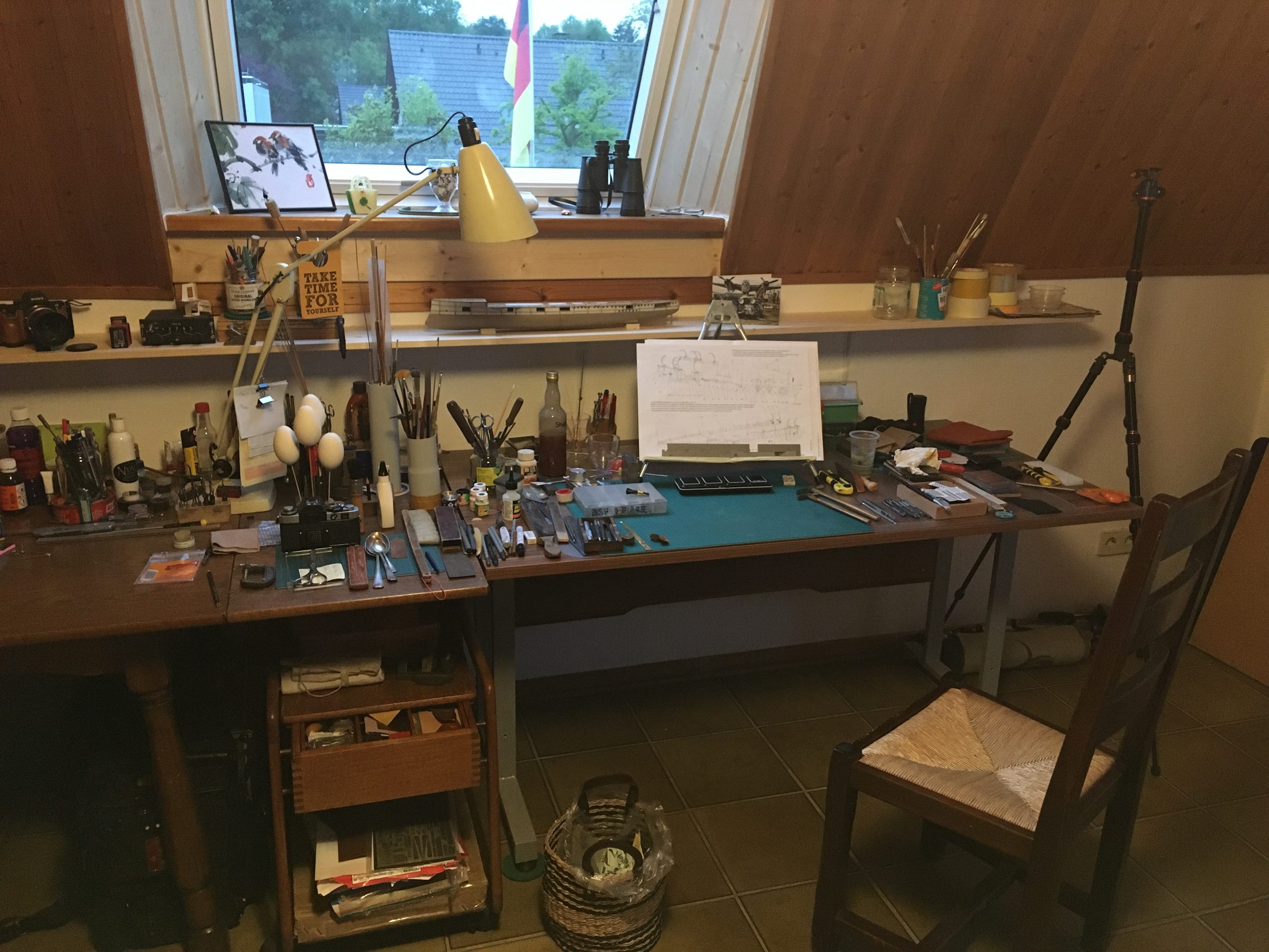
As work progresses, the bench tends gets more cluttered and has to be cleared again to move on to the next section of the work…

For the full report, please go to https://thingummybob.com/modelmaking/building-dom-bumagis-diana/