Life goes on despite the terrible war in Ukraine now for over a year…
Well, here I have acquired two metric Myfords of similar birthdates (1959 and 1960). For comparison’s sake, the one is originally a Myford Super 7 of ‘normal’ length, while the other is a rather more interesting and rarer long Super 7 bed with a ML7 drive-train and tailstock. Both of them, actually bit of a ‘bitsa’.
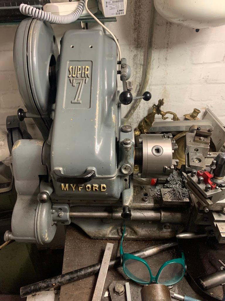
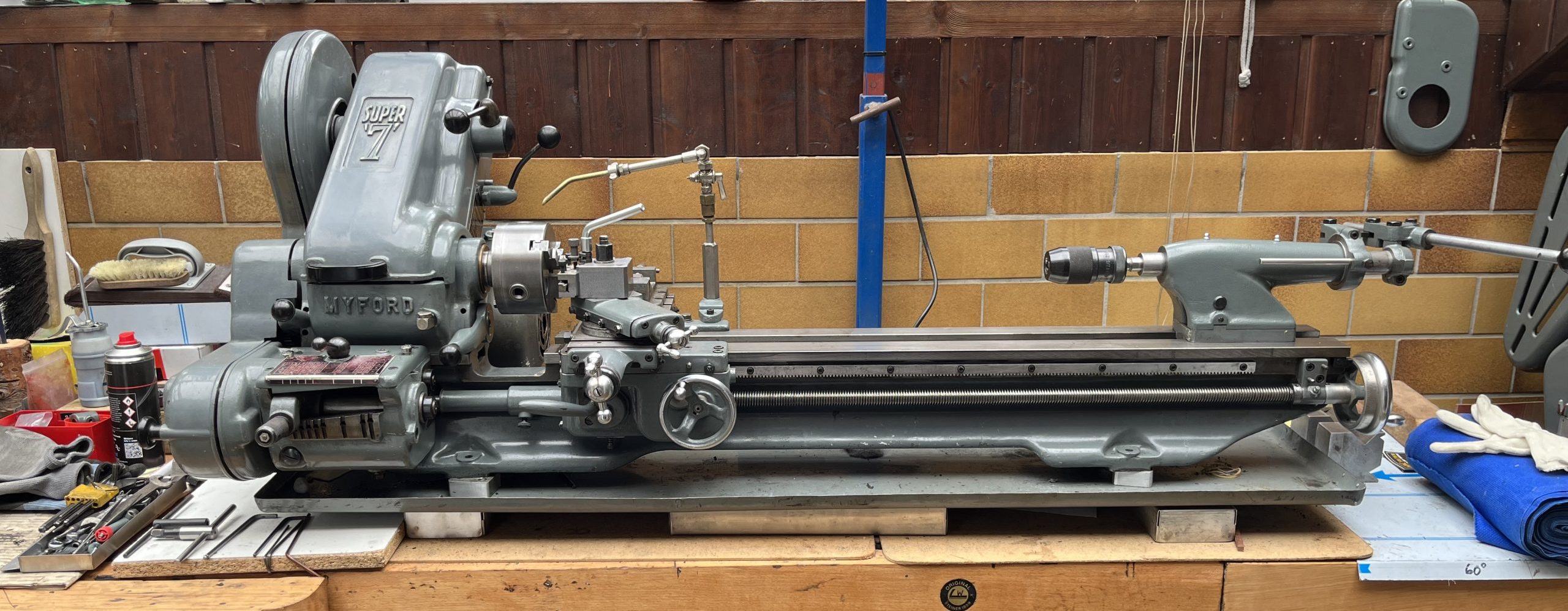
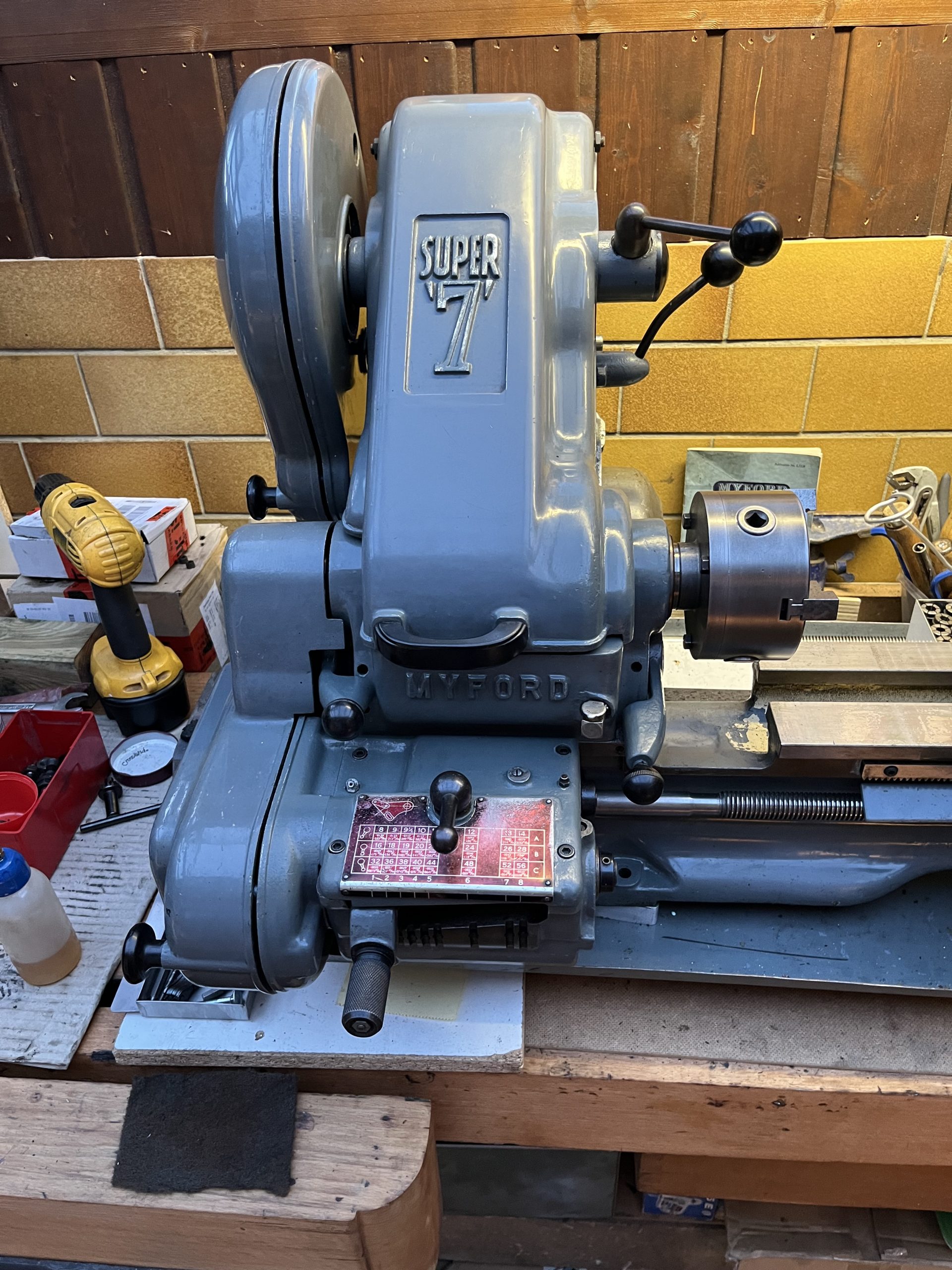
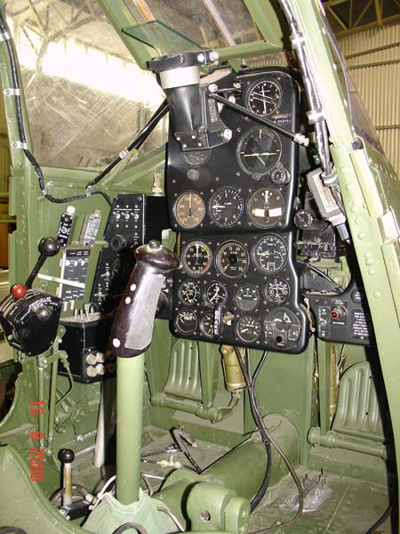
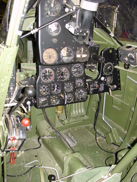
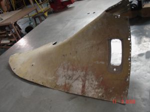
First the ‘shortie’, which is the one shown above, photographed in the seller’s cellar workshop, without any oil… I HOPE THAT HE DIDN’T RUN IT LIKE THAT; it looks like a perfectly normally shabby Super 7, it has the usual saddle and carriage , but the later top-slide (machined from a block instead of from a casting) and the rather ugly machined cross-slide end-plate. The tool-holder that came with it is one of those quick-change ‘Multifix’-style jobs which are expensive, that I am not fond of and that are a pain to set up properly. It also has only one tool-holder, as well, so why bother with the thing in the first place – the other ones were probably kept by the owner I bought it off in November of 2022 or he never received them either. It actually doesn’t work at all to my liking and is probably the reason why the sold the lathe in the first place (I’m sure that when properly setup, that ti would be great to use, but I can’t be bothered, to be honest… The rest of the Myford is OK, but has been quite heavily used in the past. The 1/3rd of the length of the bed nearest the chuck is worn more than the rest, as one would expect, and more on the back than the front. It is now being built up as an ML7 which I shall sell to ‘subsidise’ the longbed for myself, which will get the Super 7 Drive elements, headstock and tailstock off the ‘shortie’. The shorty will become an ML7 as a result.
The Longbed ML7 is in pretty good shape, especially the Super 7 bed, leadscrew, original saddle and cross-slide, which will be kept on it due to the differences in the leadscrew thread form and the split nut. Paint is in places a bit tatty, but will be cleaned up as I go along, all bearings will be replaced and the bed will be hand-scraped/flaked by myself when I feel that I need a workout!
This one came on an original Myford cabinet stand (the style of which I have not yet seen illustrated), which I shall, of course, be keeping. The door is, I think a later addition, as is the ‘drip tray’, which looks sort of home-brewed. I will add a cutting-fluid feed, for which I also found the important parts.
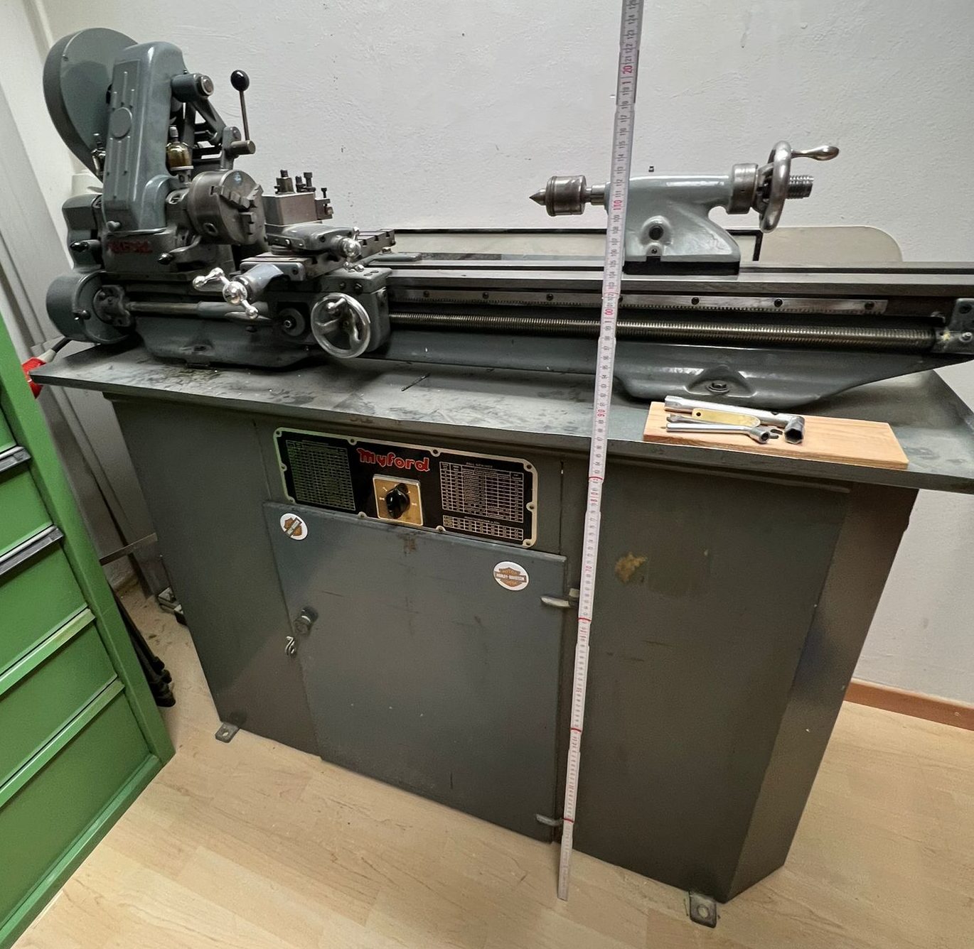
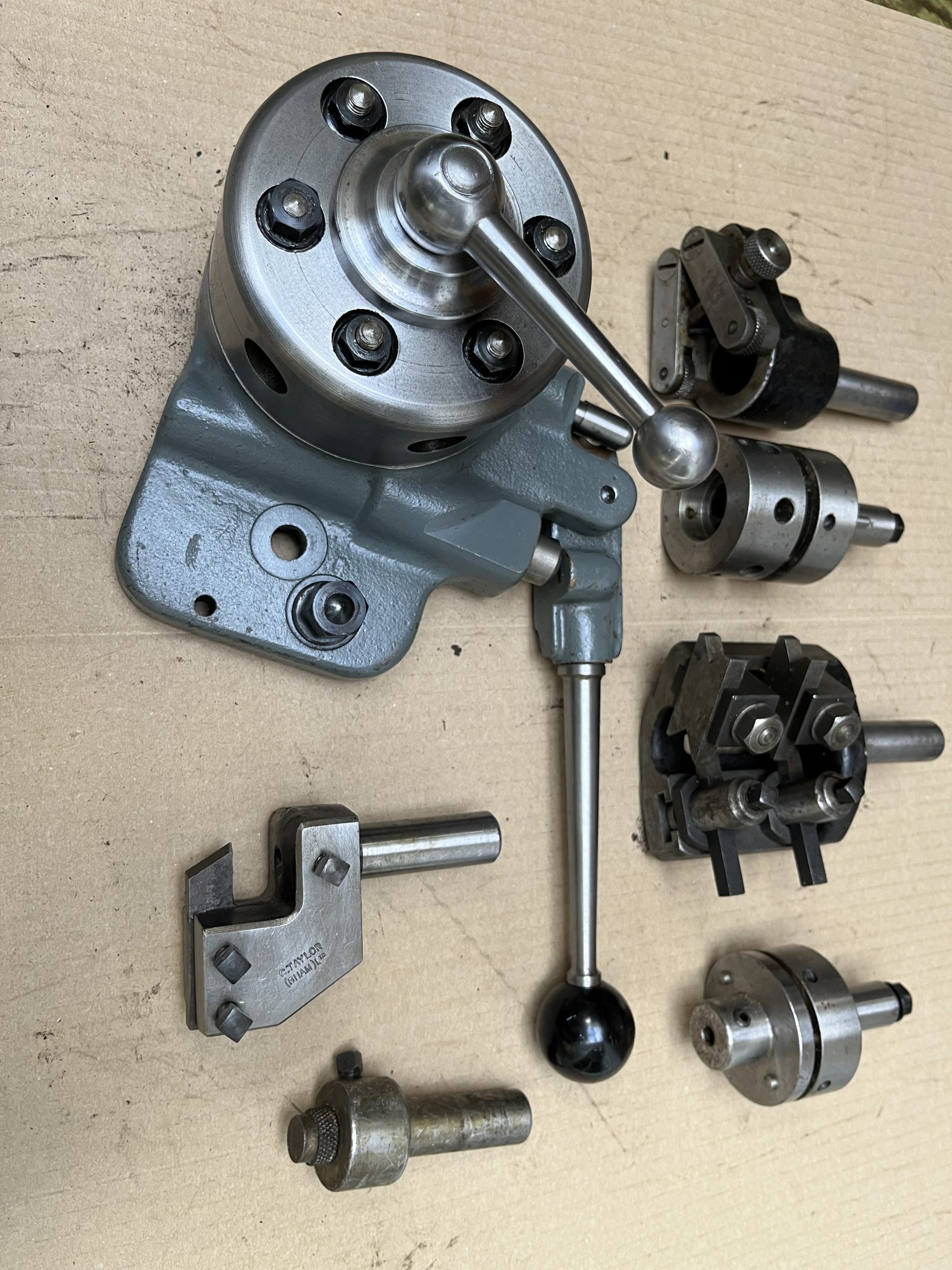
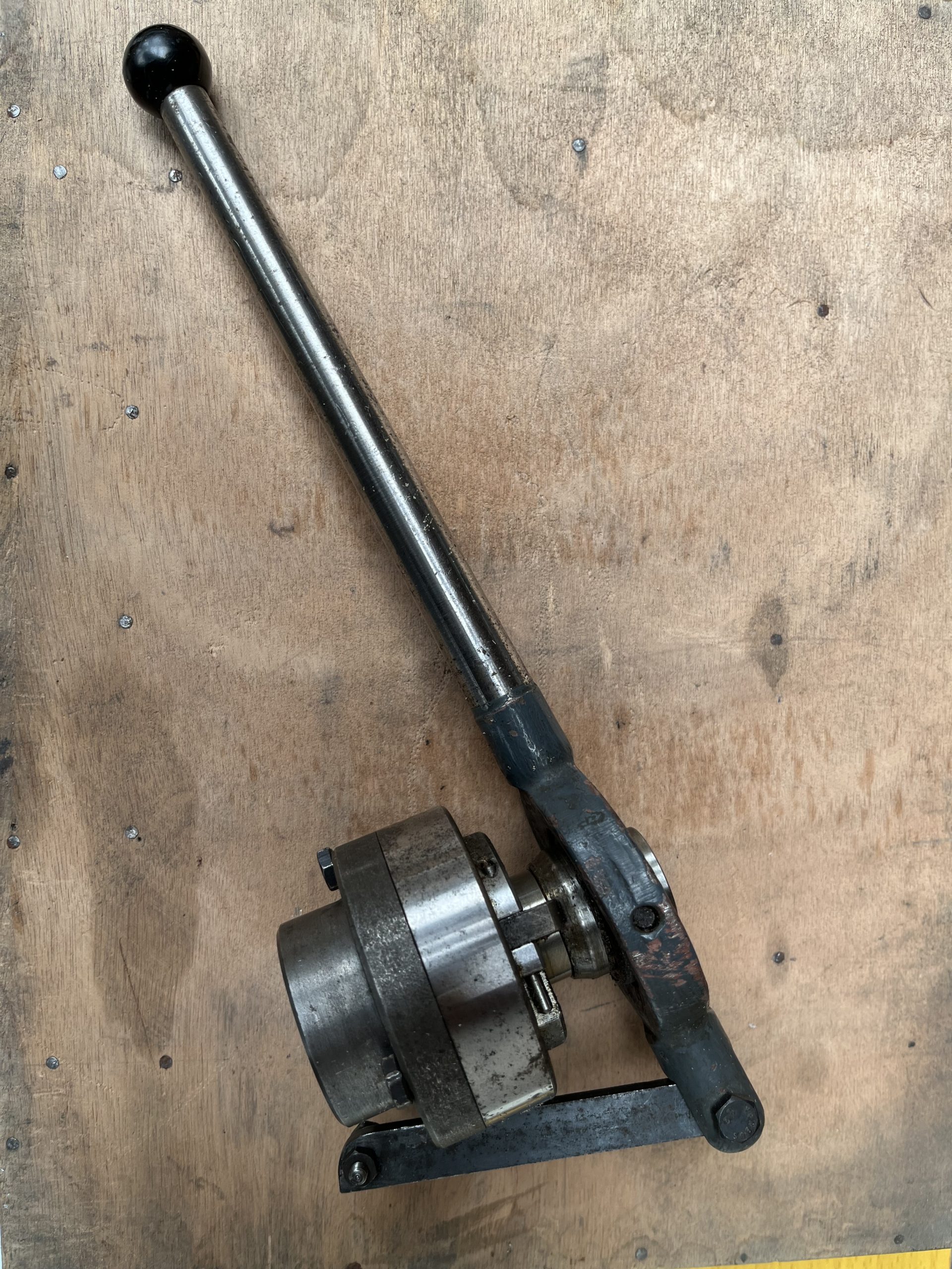
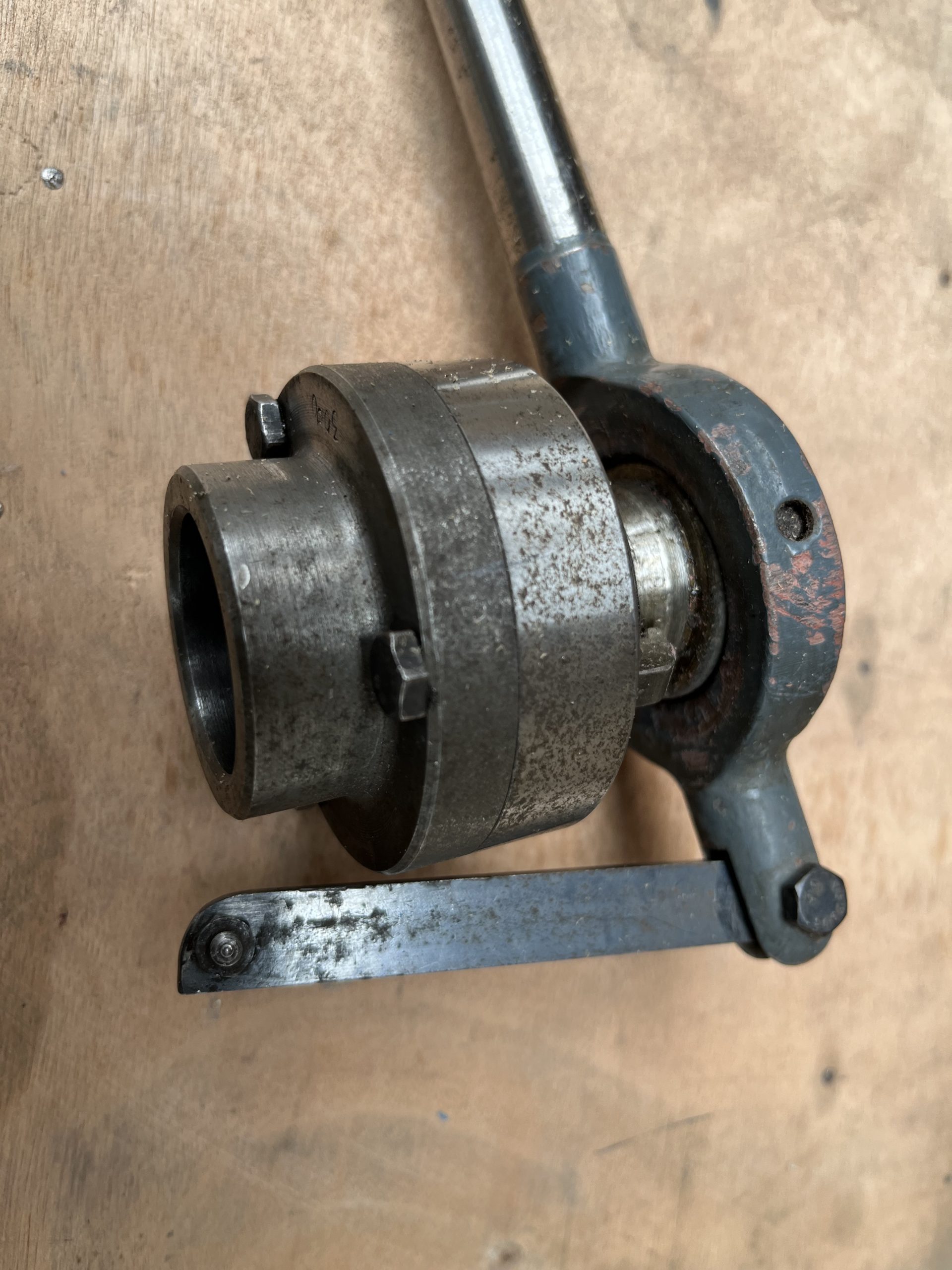
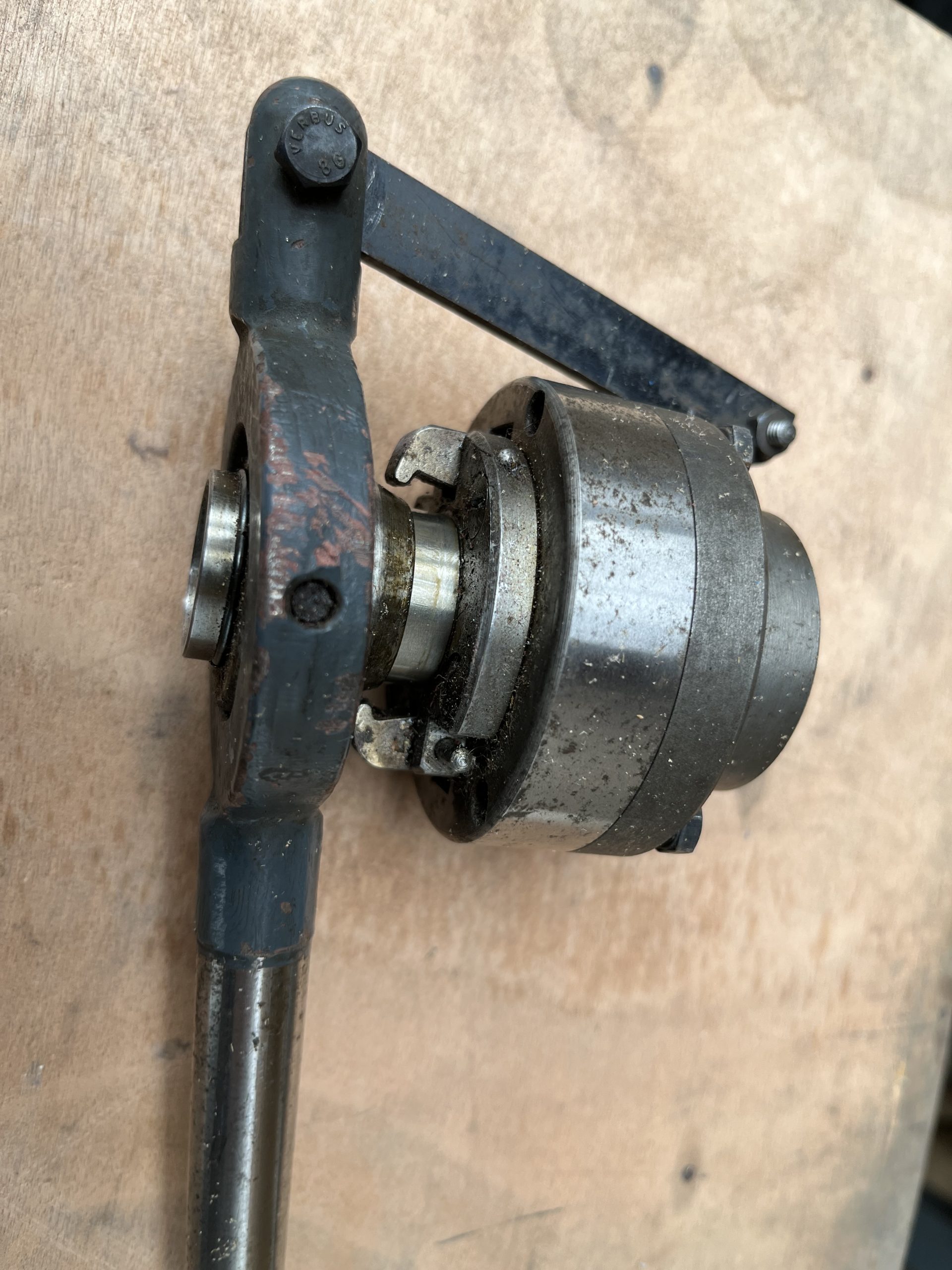
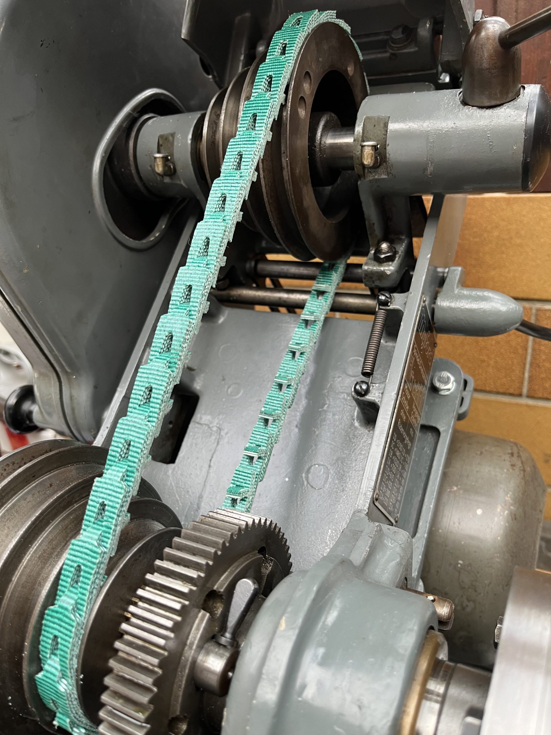
KSL 49296 also had a few accessories with it including original toolholder and a quick-change ‘four-poster’, some face-plates and a nice fast chuck for the tailpost, along with lots of change-gears. Both of them have 380/400 Volt motors, which I can use at home with the necessary emulator/converter giving the same power output from the motor without having to get a 400V. setup installed by an electrician. The cost of the ‘black box’ and switches is around €250 (or up to €650 if you really want to pay that much) for everything, so actually cheaper than a new motor and is portable, so usable on any other machines that I might get in the future with ‘Starkstrom’! The beauty of that is that the 400V motors runs a lot smoother and gives a better finish than the jittery single-phase ones and they are not as sensitive to frequent switching on and off – in this case not so important for me as the Super7 has a clutch (missing on the ML7). Being a 1959 model, it is the first clutch system, for which there are no longer parents, but the last one I had ran perfectly, so I’m hoping that this will do so as well.
I started work on the shortie a few weeks ago and since they were both dismantled for transport and had already been carried upstairs(!) to work on on my closed balcony, I thought that I would start with stripping and painting the bed. My left elbow has been playing up again after my mishap with the Husqvarna a while back, so I thought some light work was the best place to start!
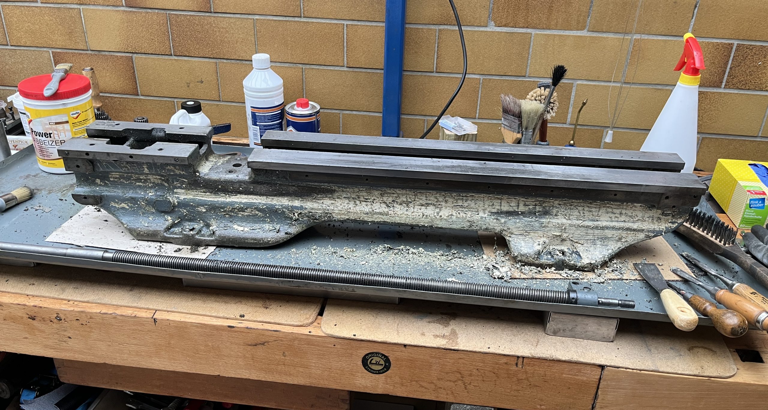
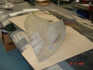
Oops, that was a lot easier said than done. Although the paint looked tatty, cracked and scrubbed off in places, it is VERY tough and difficult to remove, especially since the ‘modern’, ecologically-friendly paint-strippers commercially available here in Germany are largely useless on older oil-based and baked on finishes. I tried multiple applications, scraping and scratching in-between coats which was pretty ineffective; in the end I resorted to the even messier ‘abrasive’ method, causing huge amounts of dust. Here some pictures of my efforts:
Scraped with flat and half-round chisels after a thick coat of paint-stripper: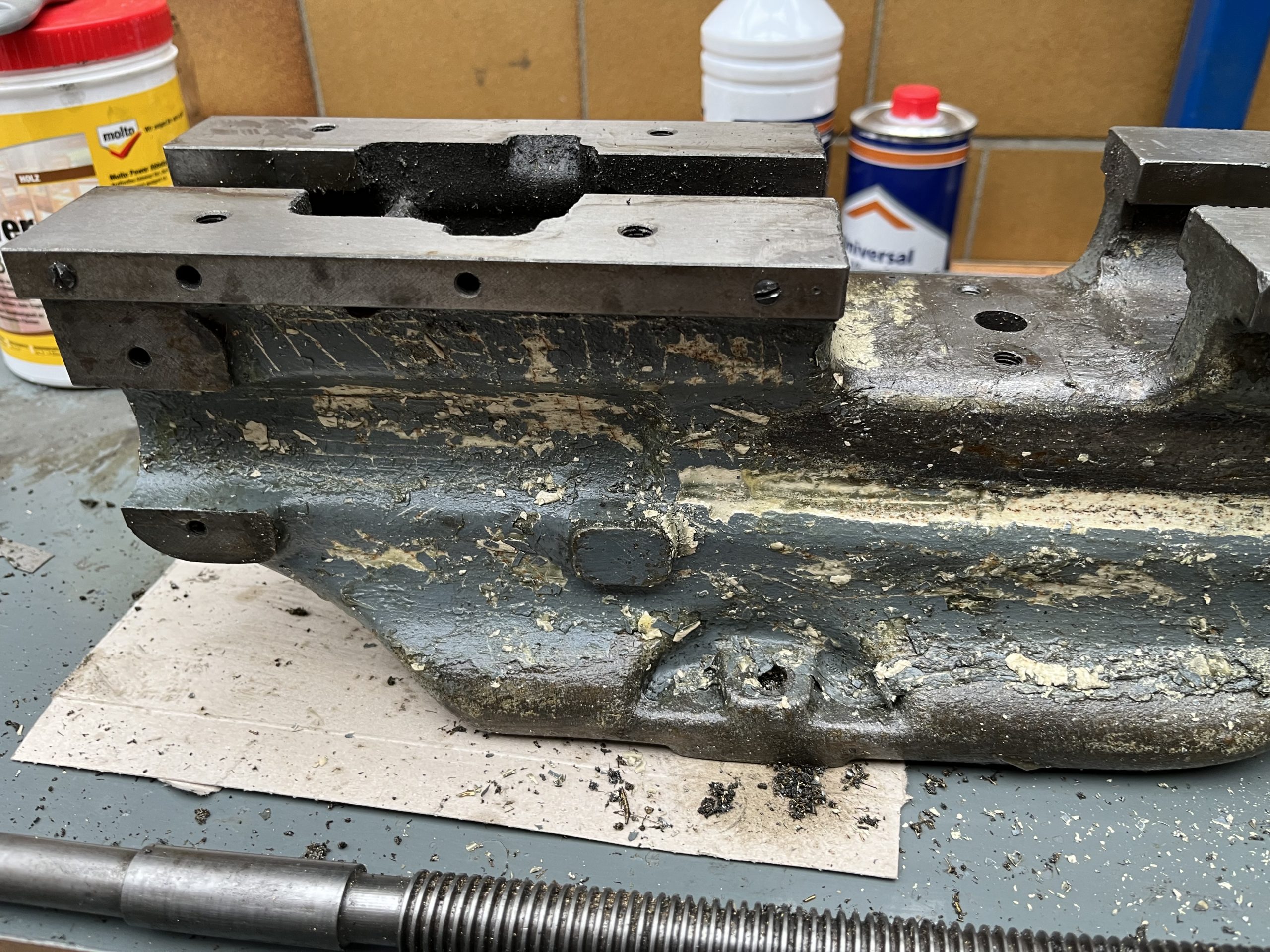
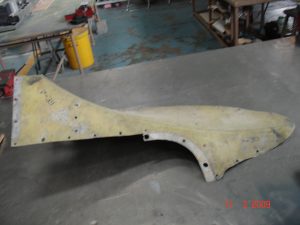
After the second application etc: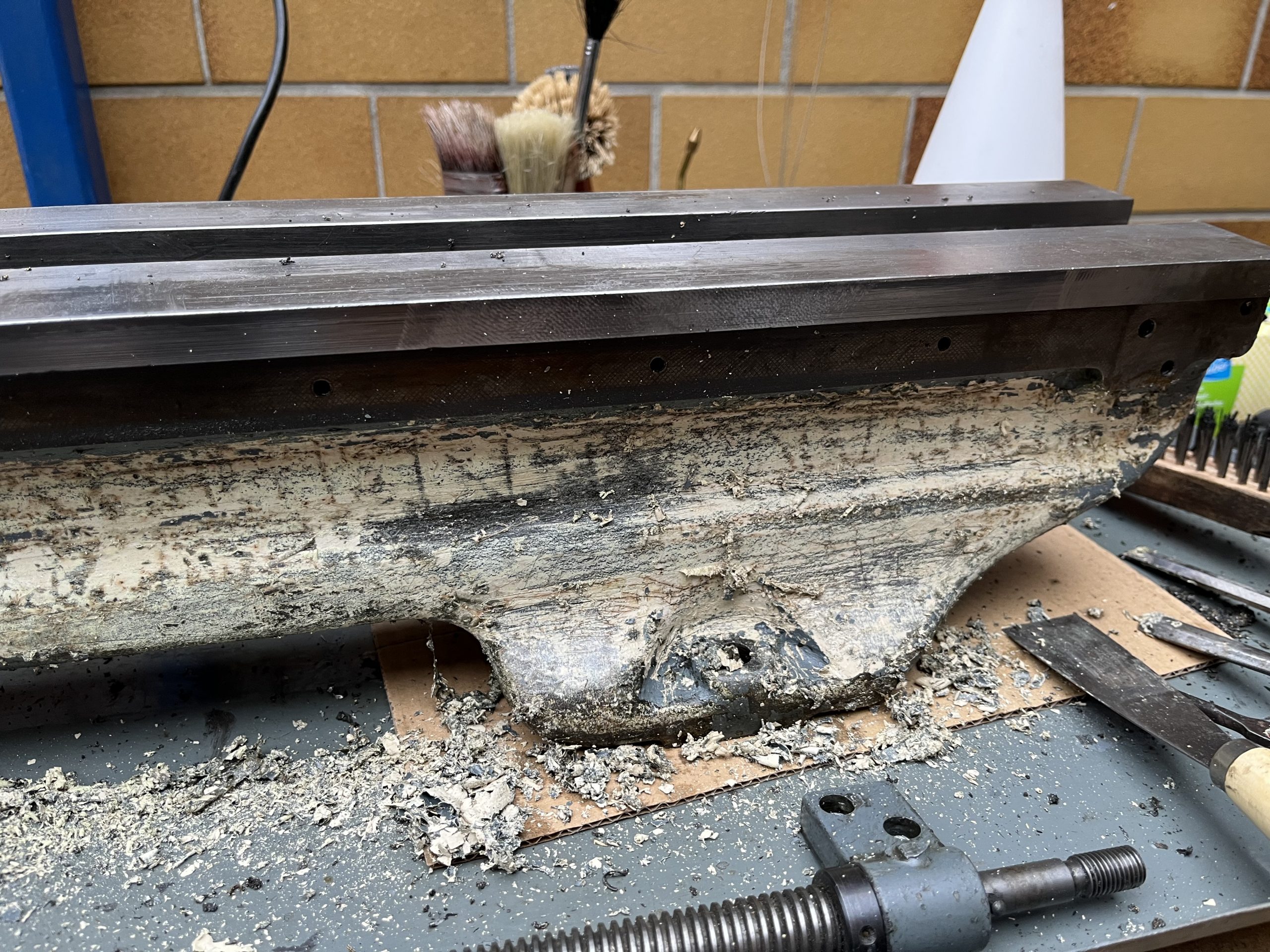
This was a workout for sure… all done with the right hand 🙂
Here with a first coat of primer: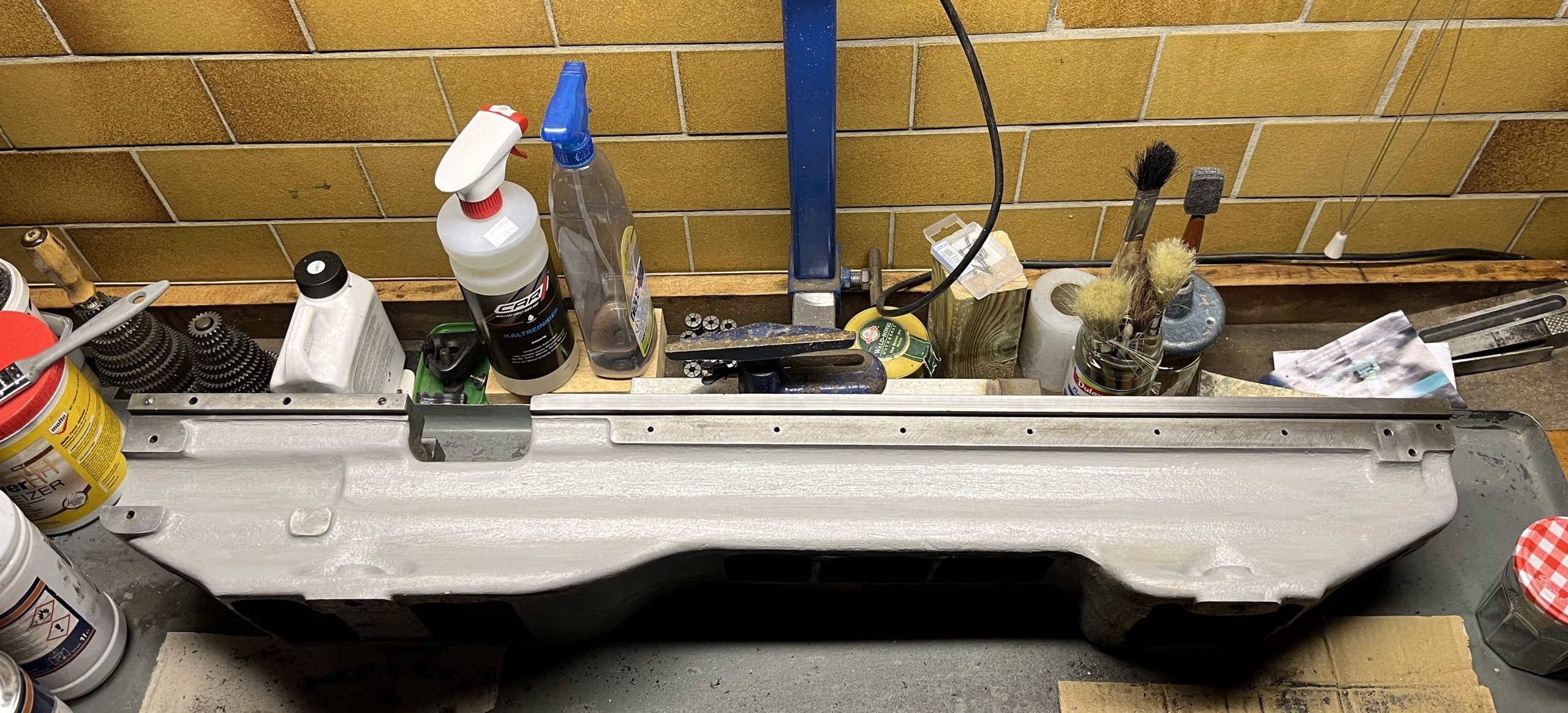
Front and back were treated to a proper cleanup, both easily accessible just by tipping forwards or back and a wire-brush (which had the negative effect of closing the pores), so everything had to be sanded again to give a key to the paint. Primed with Hammerite applied with a brush. After priming, the whole thing was treated to a few coats of Myford Old Grey (from RDG) with a roller and my own mix of pale yellow pigment mixed into Hammerite gloss white between the shears. Eventually looked like this and this is how it will go to the grinder’s – if I can find someone willing to do the job…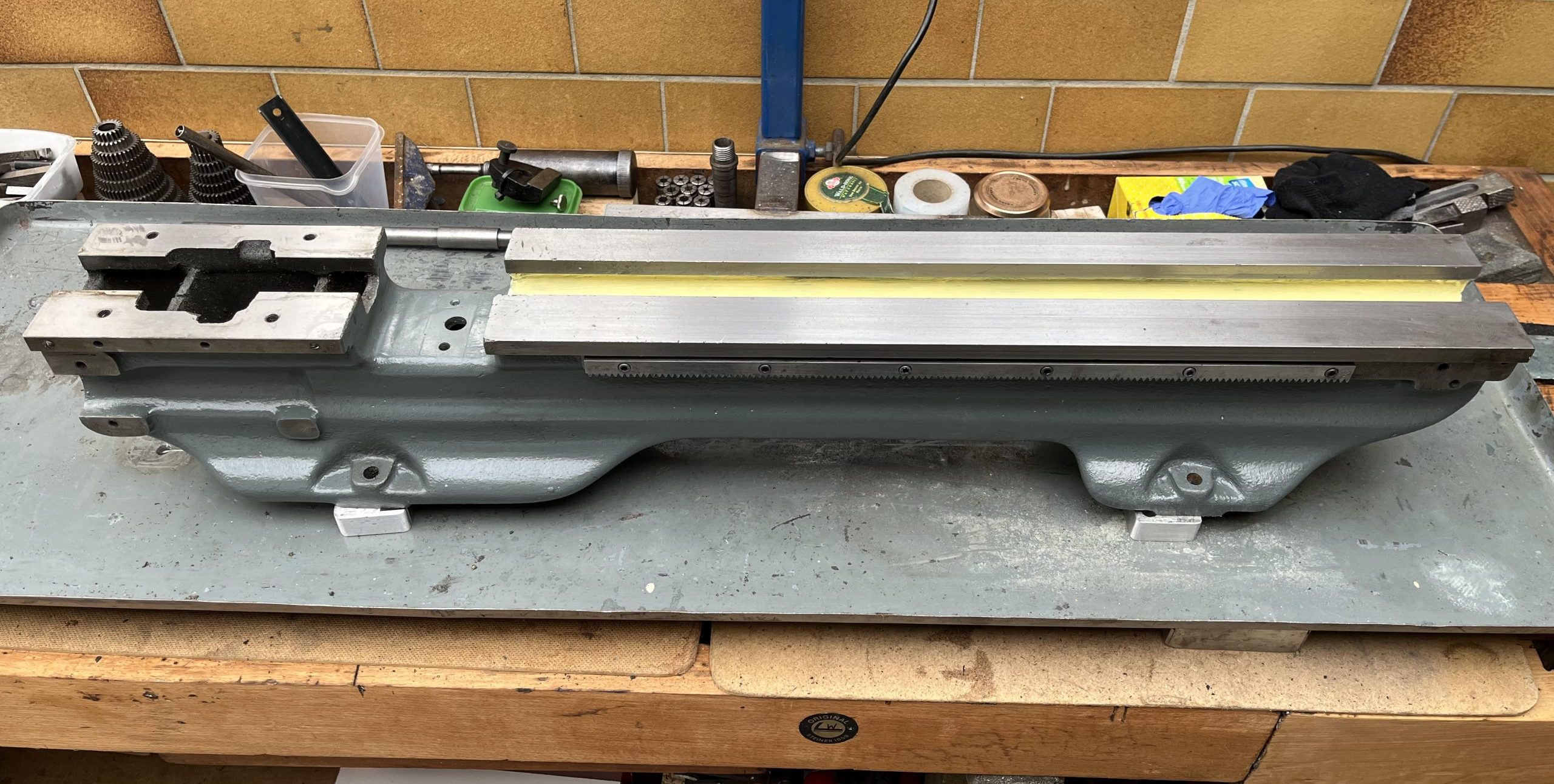
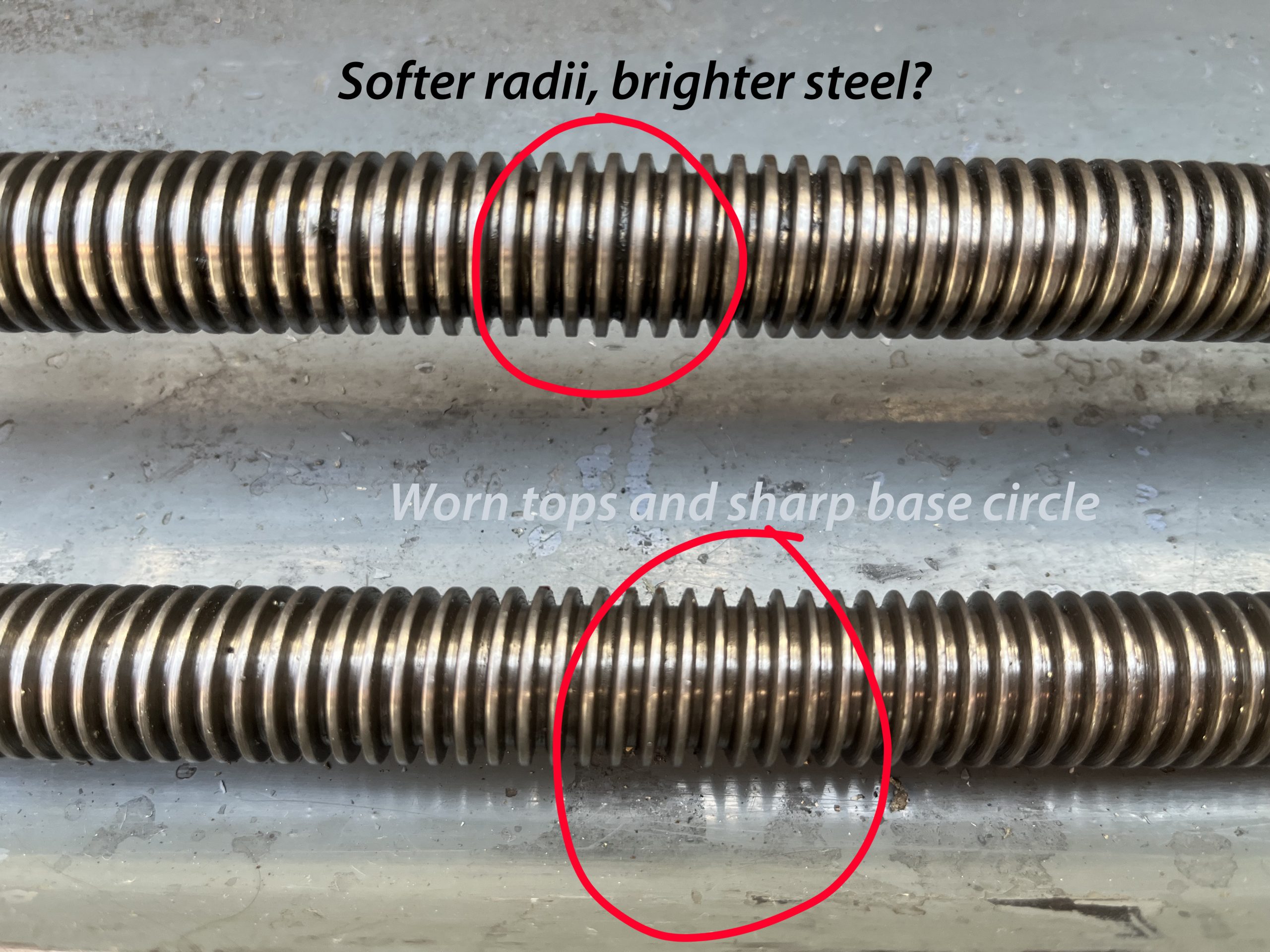
I also treated the carriage/saddlle/apron and tailstock to the re-painting treatment and cleaned up the contact surfaces. The split nut is of bronze, which is suspicious…Perhaps a later purchase? Wrong material, wears far too quickly and is probably the cause of the wear on the leadscrew. At the moment the split nut is not easily available to buy, but the leadscrew is also fairly worn from about 1/6th up to ¼ of its threaded length, so both would need replacing at the same time, of course to do the job properly. Interesting to note is that both lead screws have 8tpi, but a slightly different threadform!
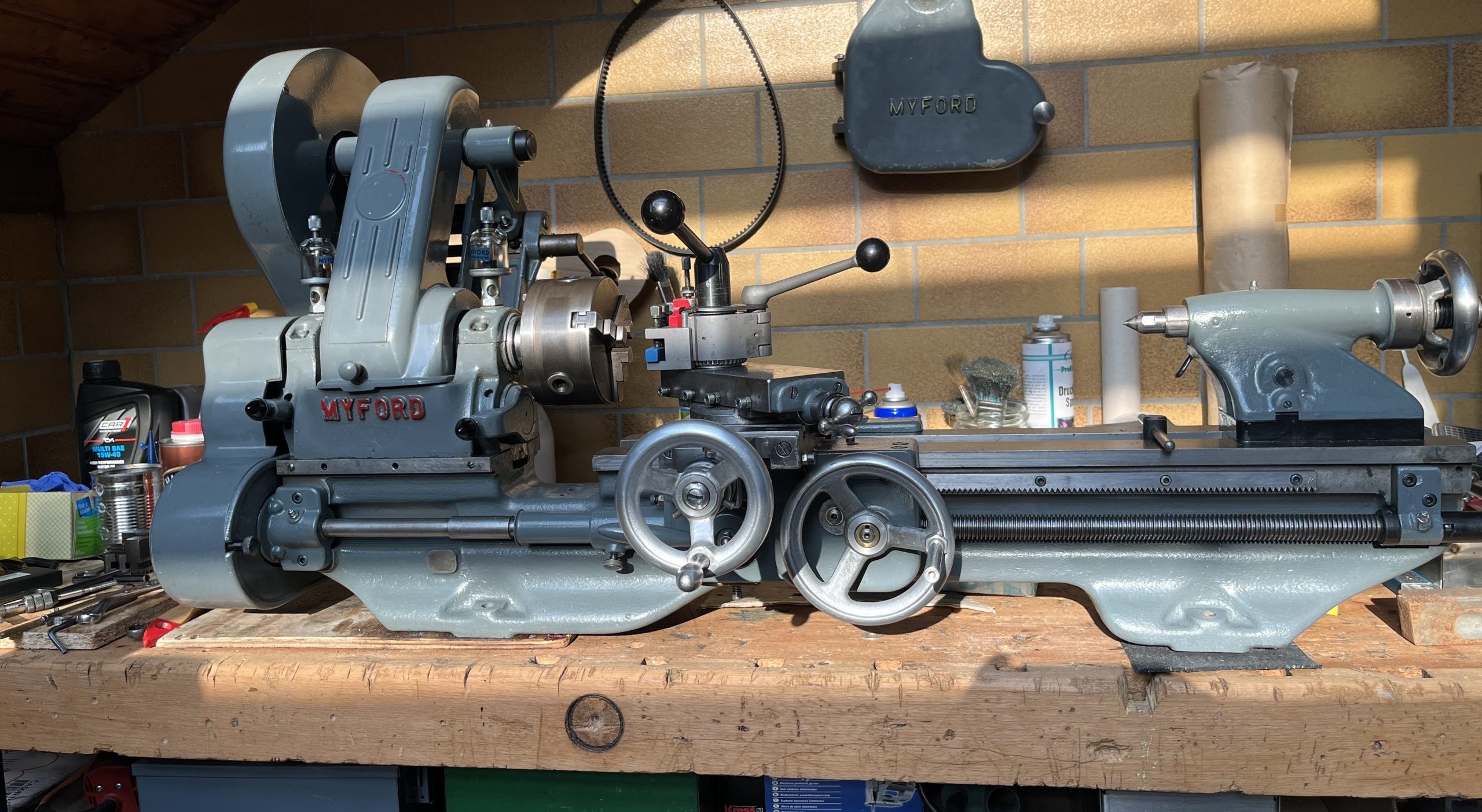
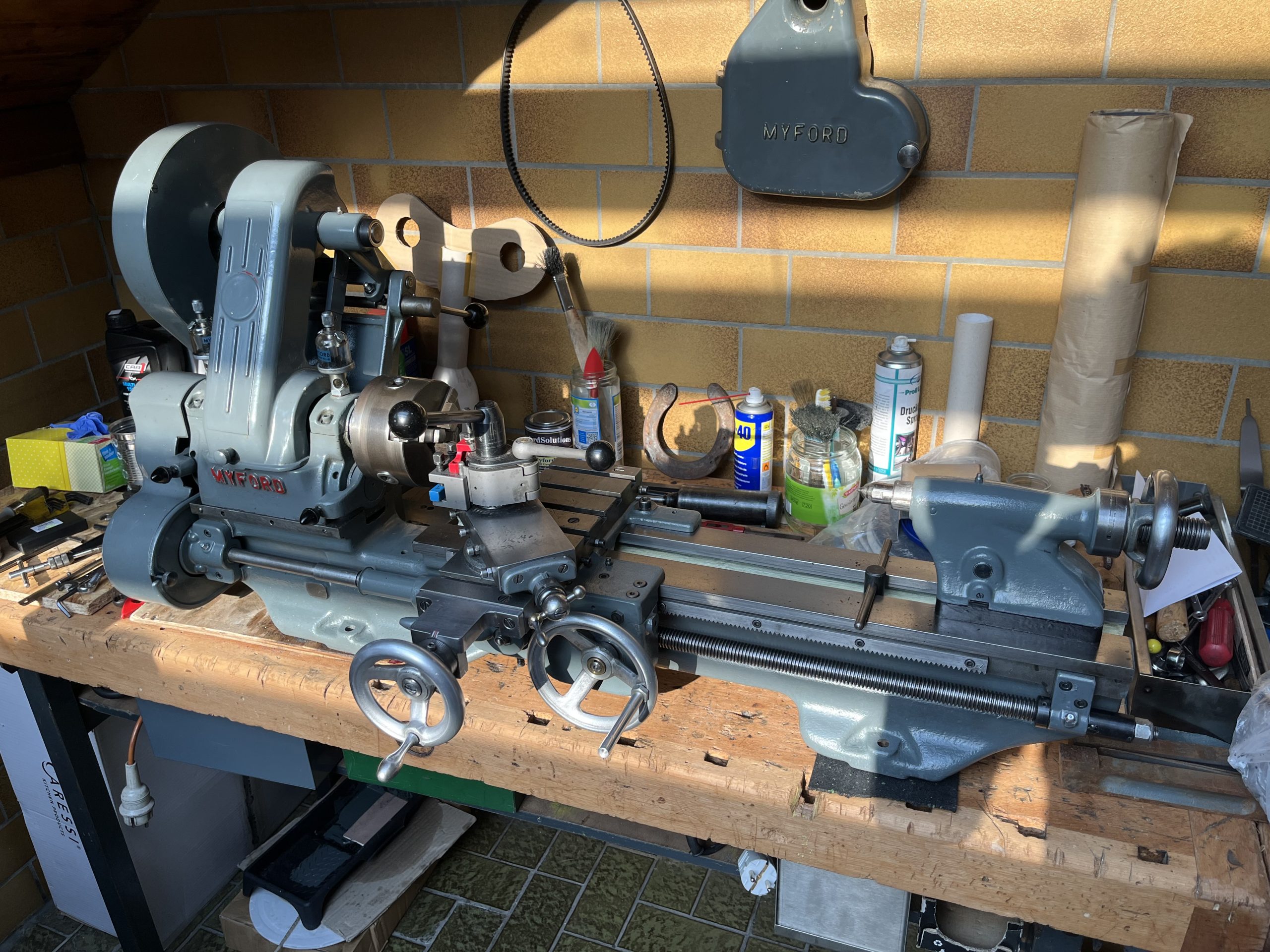
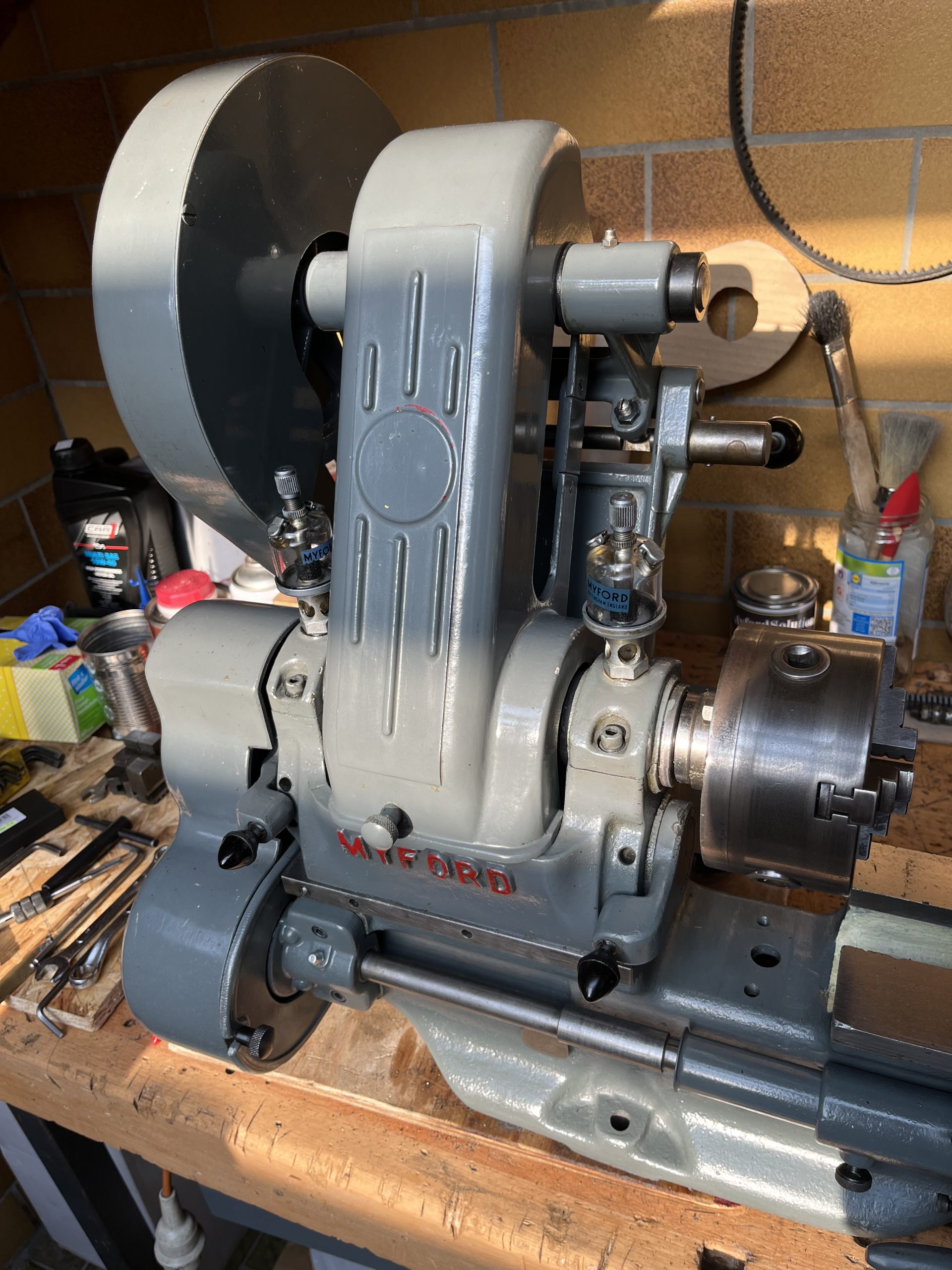
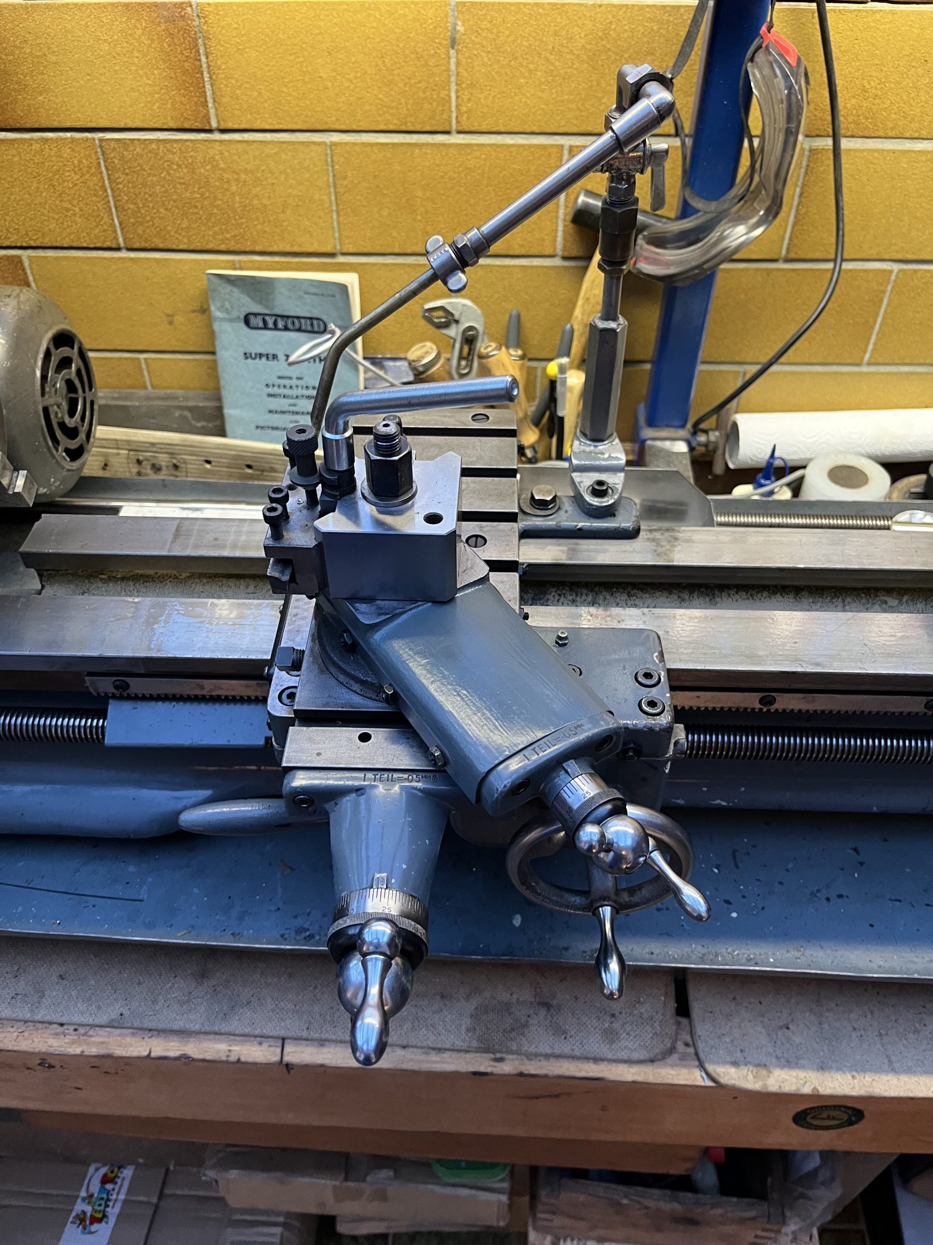
Here is a photo of the setup provisionally put together, sans tailstock. All will have to taken off to get the bed reground, naturally. All done in a jiffy 🙂

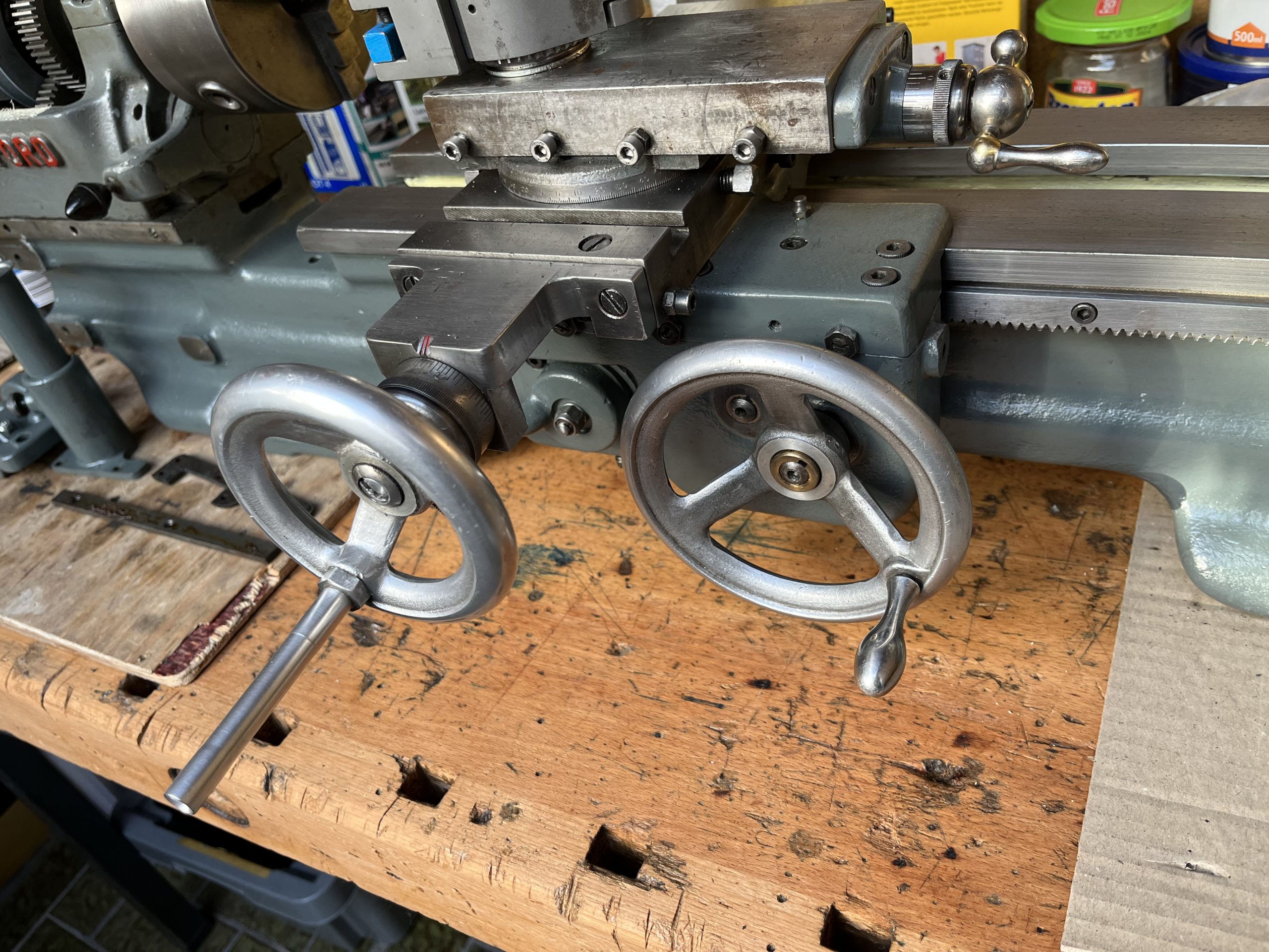
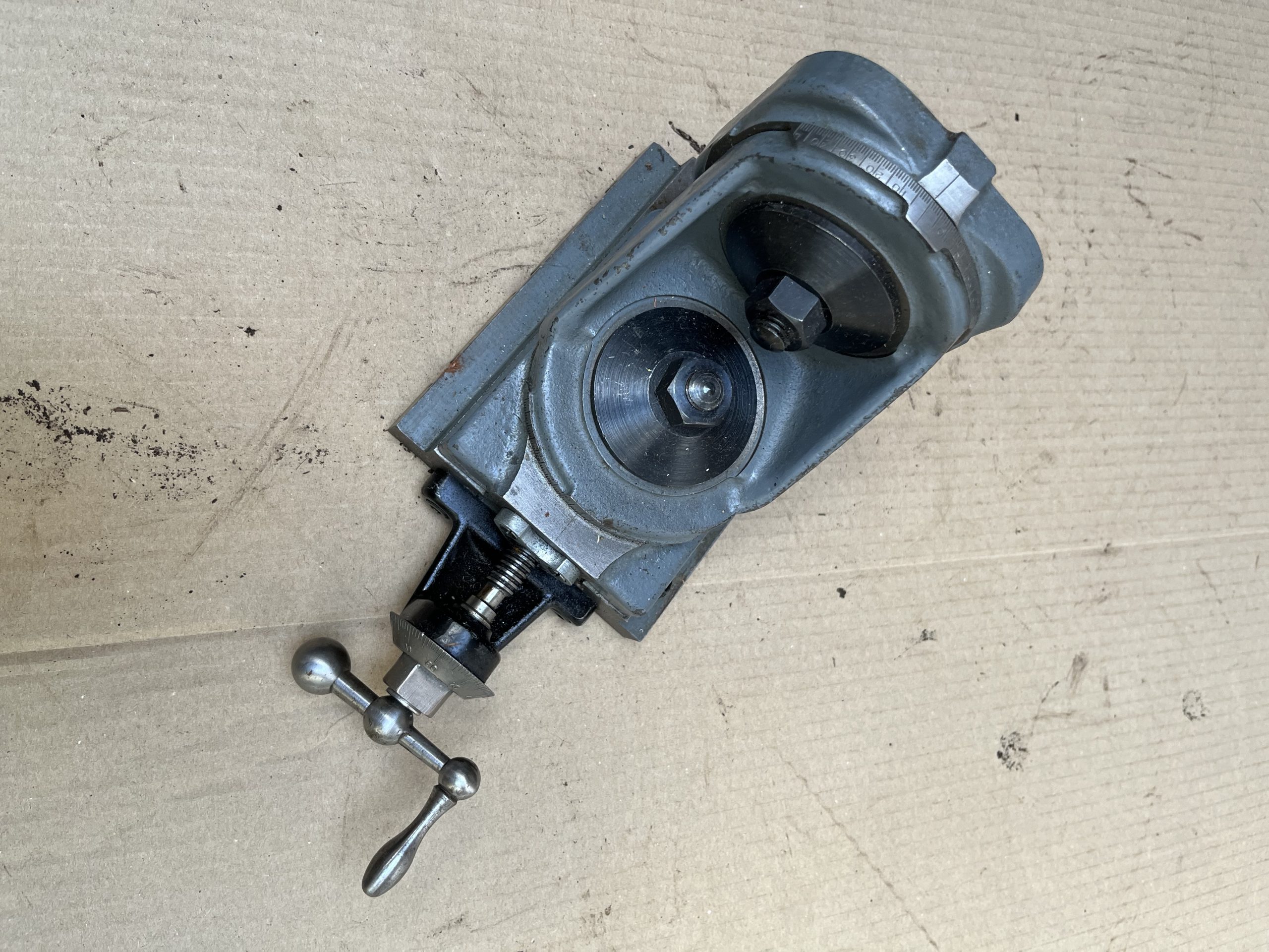
Here the rather square top slide and cross-slide end plate are fairly obvious, as are the large hand wheel on the apron (which catches your fingers on the corners of the cross-slide when you wind quickly, if you are not careful!) and the home-made ‘teardrop’ on the cross-slide hand wheel. Also visible is the ‘Multifix’-style tool holder.
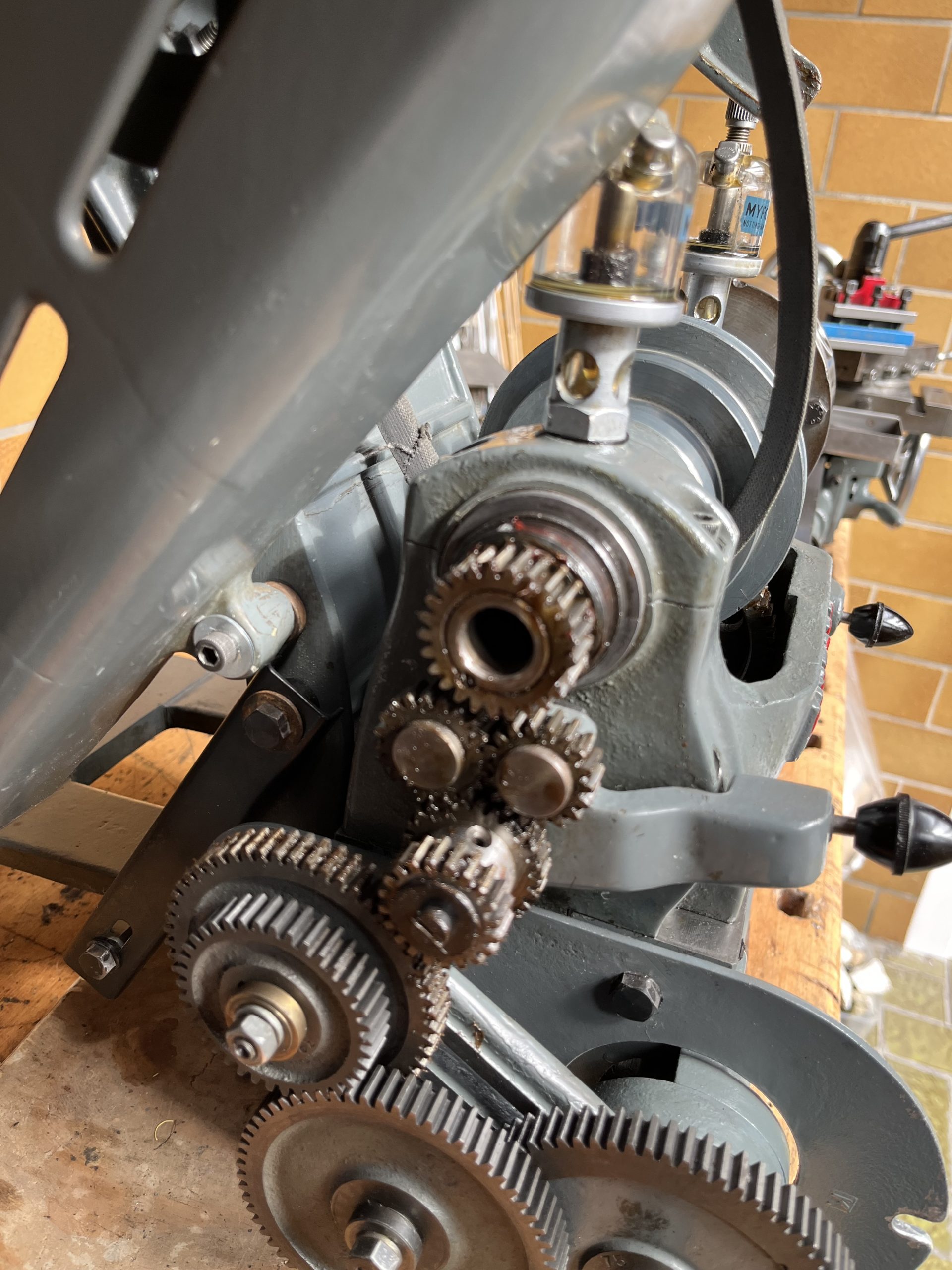
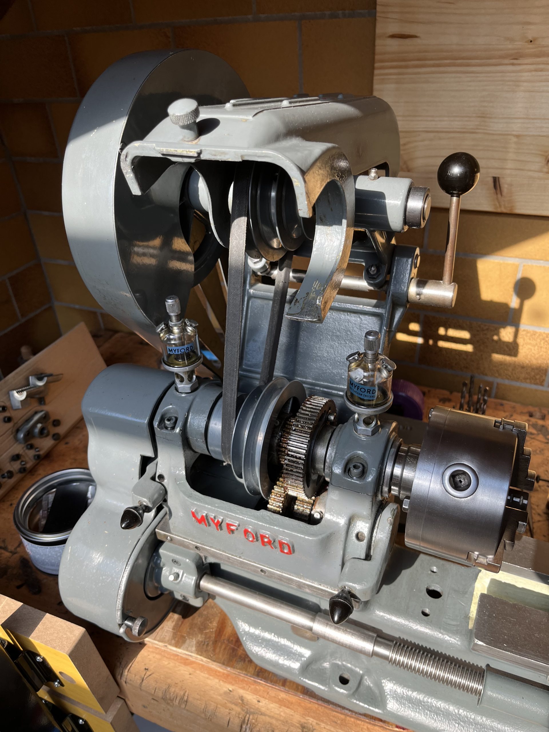
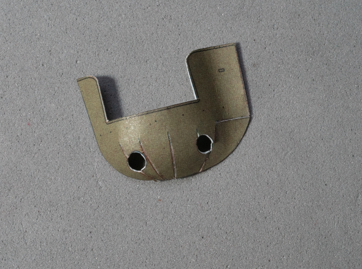
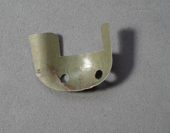
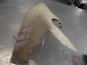
Here are a couple of pictures to show the difference between the two: the first is as ‘should’ be for the Super 7 (notice the top-slide casting and the cross-slide end plate) and the second is what I received on the shorty (originally Super 7).
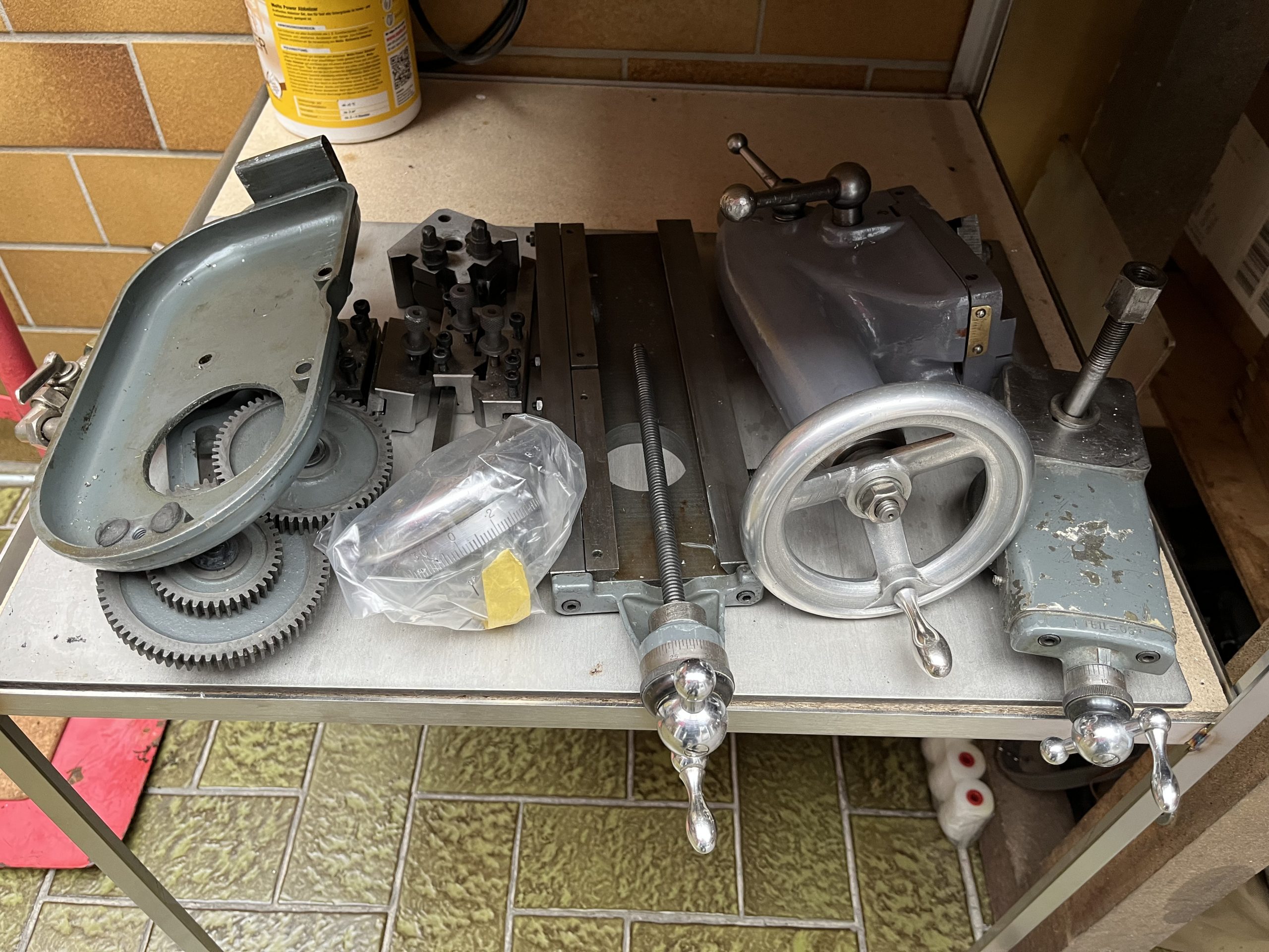
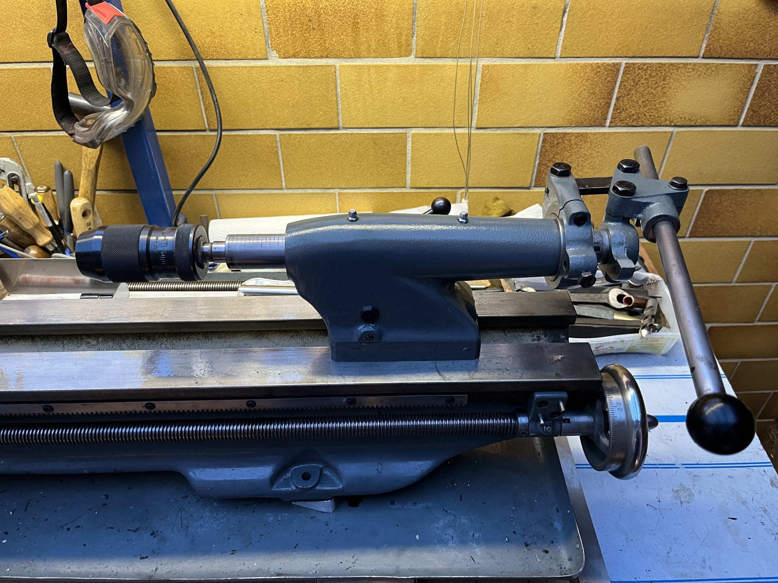
The wheel on the left is what was probably originally fitted to the apron and the one on the apron originally came off a tailstock (compare with the above picture) – apart from the modification! The topside hasn’t been cleaned up yet – that will come later.
———————————————————————————————————————————————————–
02.03.2023
Yesterday I got a call-back from a machine-shop, who said that I could bring the bed around and he would do it for me. So I did just that. Later around 13:00h, he called to say that it was done! Well, I was shocked, as nearly everyone else I called obviously didn’t want to to ‘bother’ with it. So I picked up the standard-bed SK 7246 from the toolmaker’s, NAD-Form, in Lage, Westfalen. Beautifully fine grinding job. Not for nuffink (but very reasonable, I must say), of course, but well worth it, as the shears were rather worn ‘all over the place’. 2 tenths of a mm or nearly ten thou taken off to clean up 99.9%, so not that bad, but better done than not.
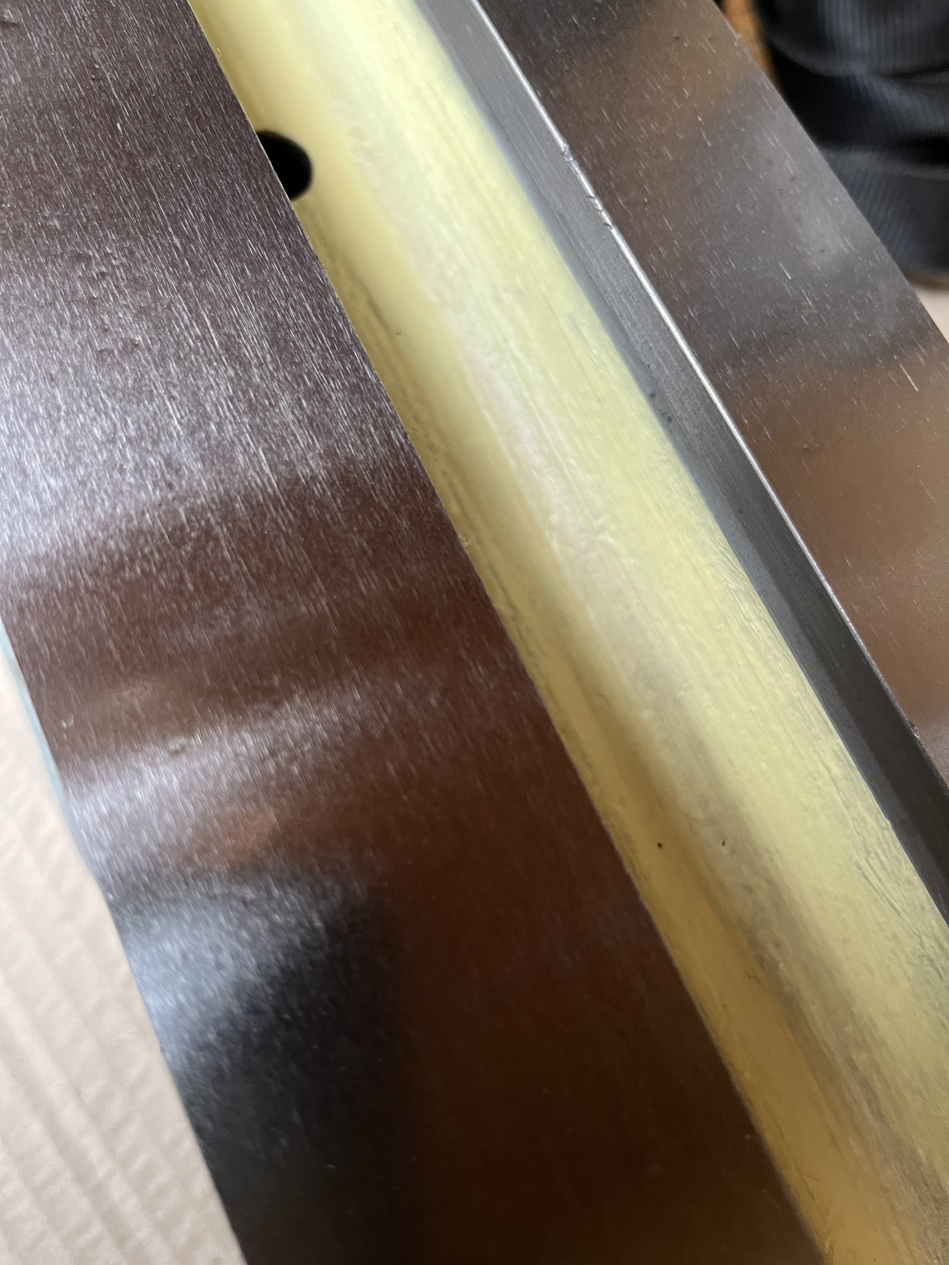
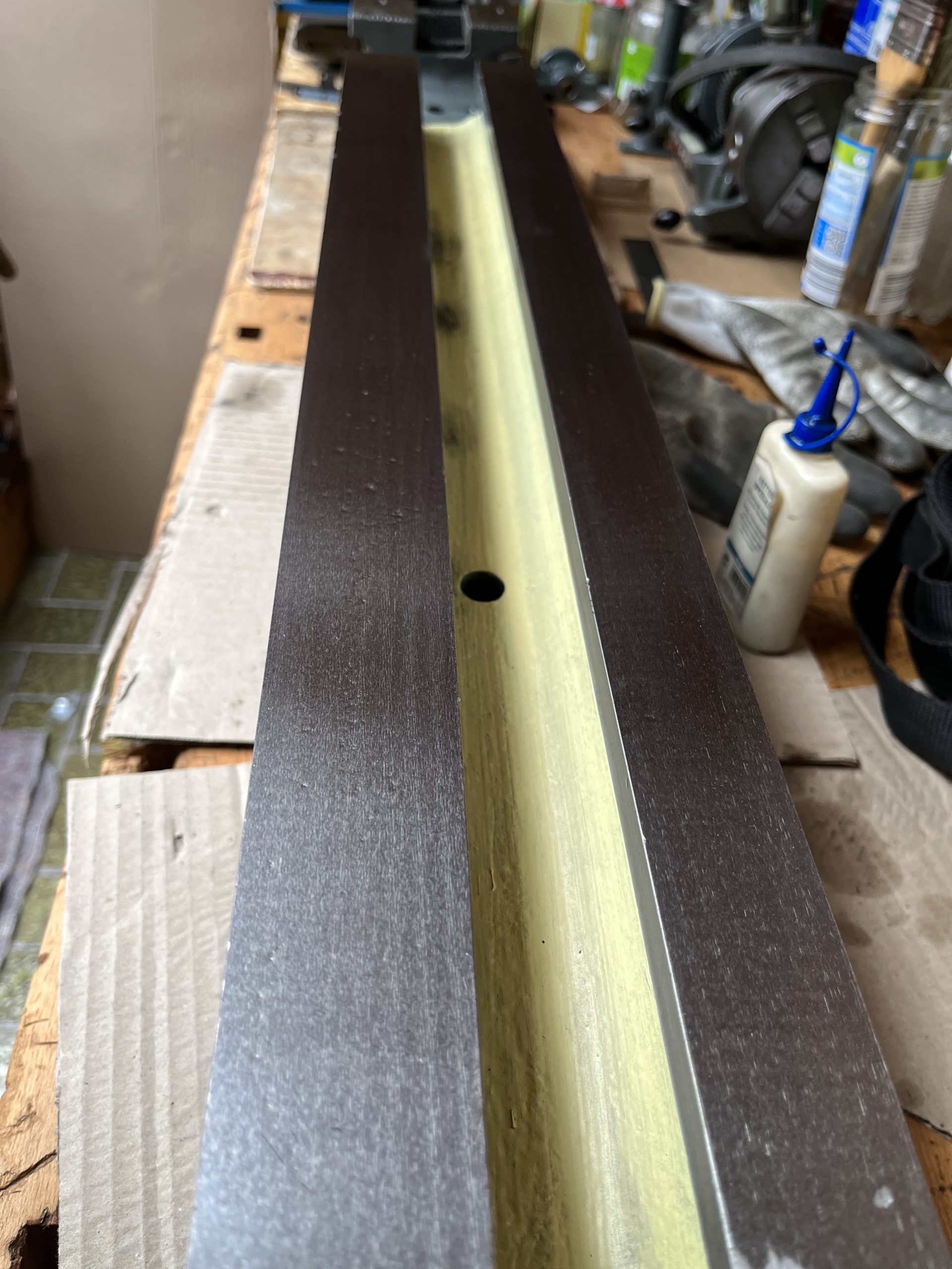
Pictures taken before stoning but after smearing a bit of cycle-chain oil on them for preservation!
———————————————————————————————————————————————————–
24. 03. 2023
Well, I just discovered that the ML7 and the Super7 have different mountings and castings for the motoring department, which means that I have to measure, mark, drill and tap the back of both beds to swap them over to the respective types. Thankfully this is the only ‘surprise’ awaiting anyone doing the same ‘conversion’,is not difficult to do and allows the re-conversion back to the original configuration without any limitations. Pictures to follow, of course, when I get around to it. Left elbow still enjoying being ugly and hurting 🙂
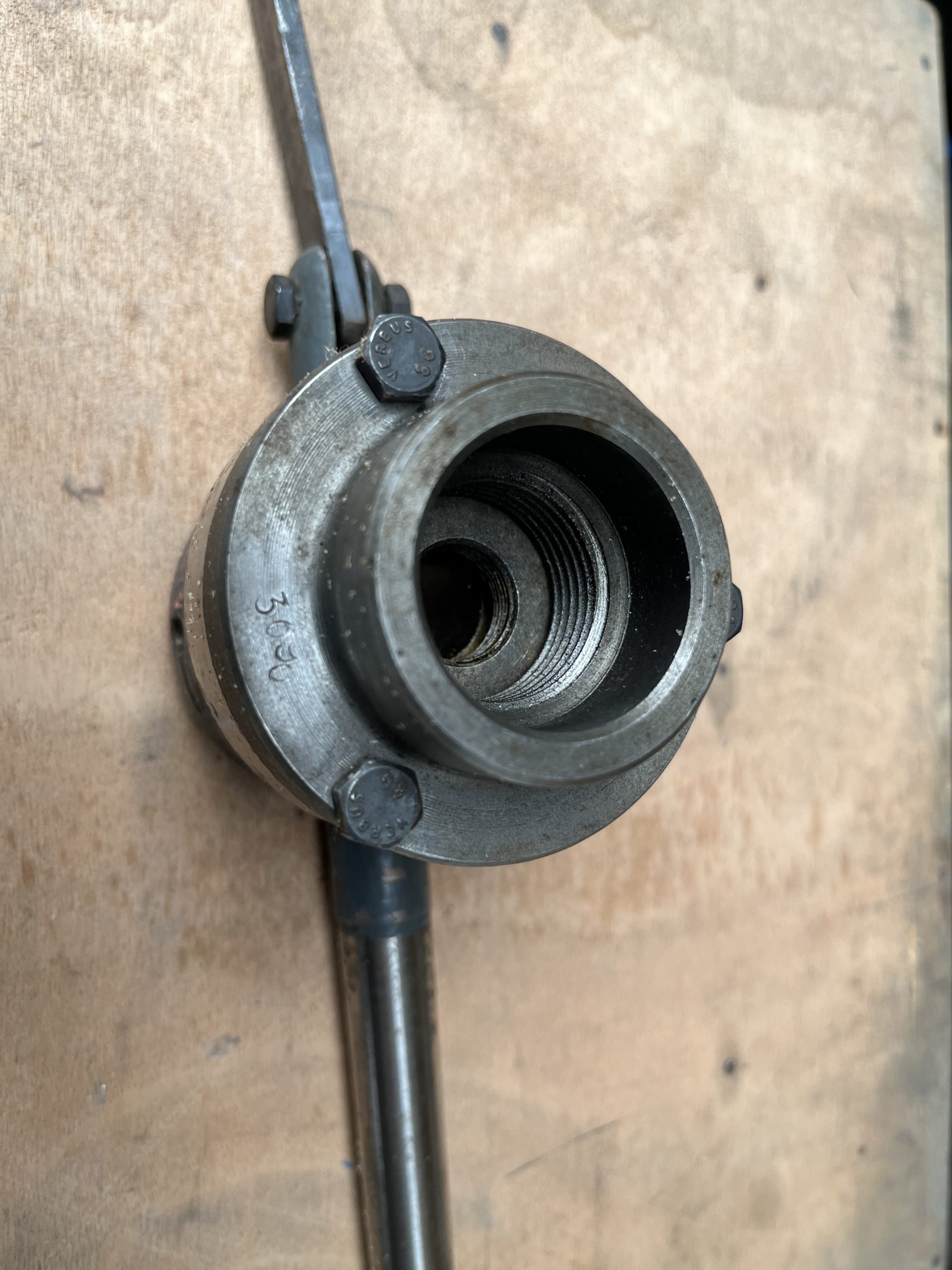 Here are the dimensions:
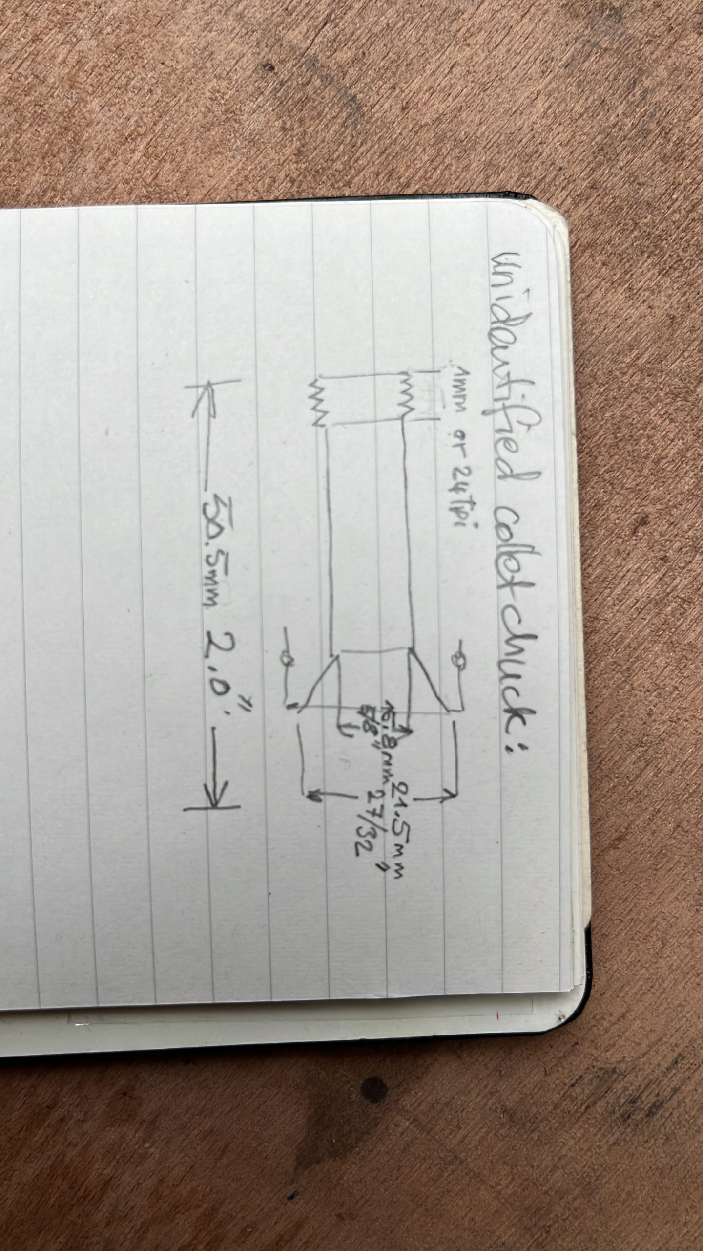
 Now standing in the corner minus chuck, headstock and motor (stored underneath the bench!)
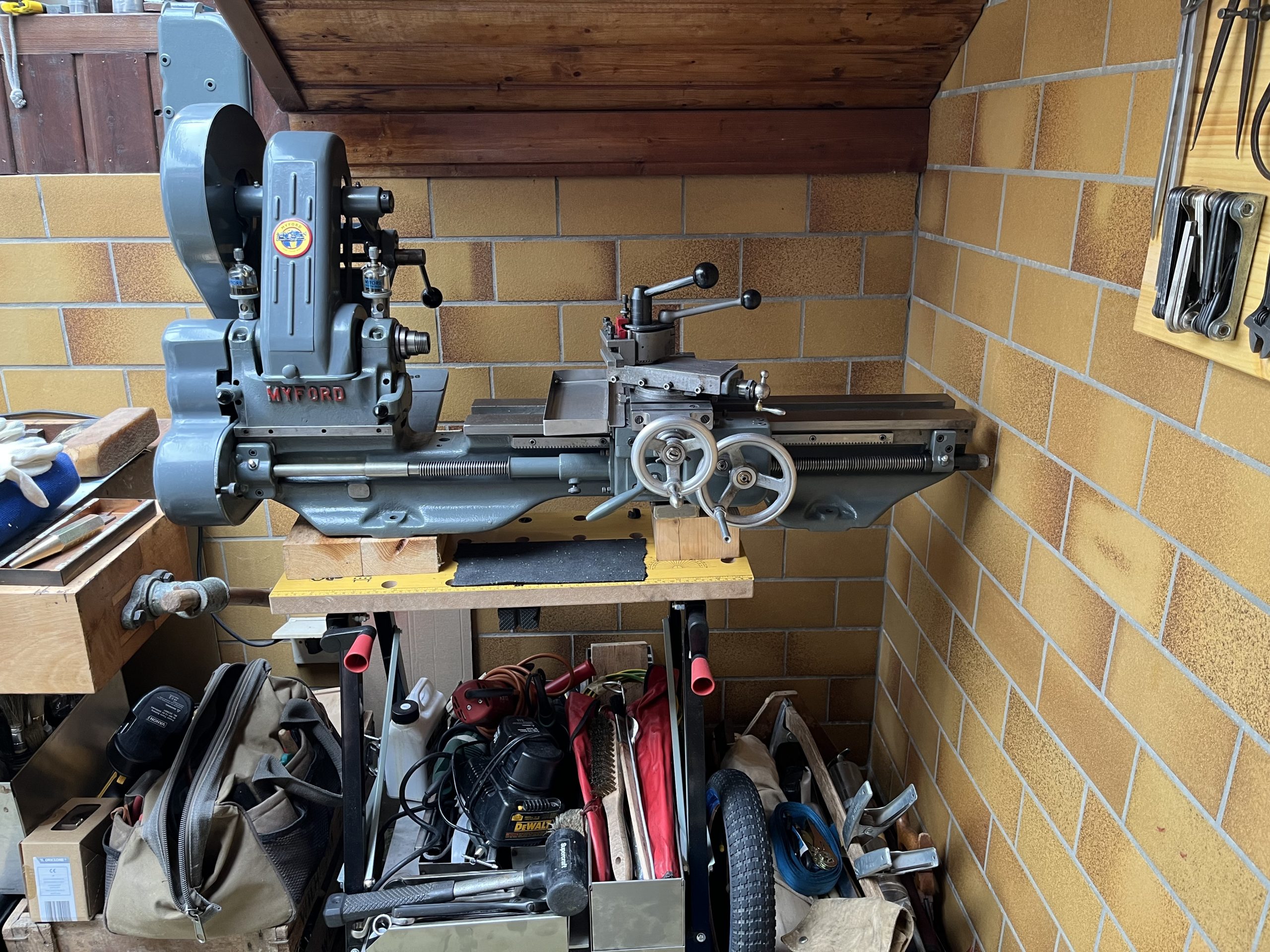


