Minolta AES Viewfinder repair

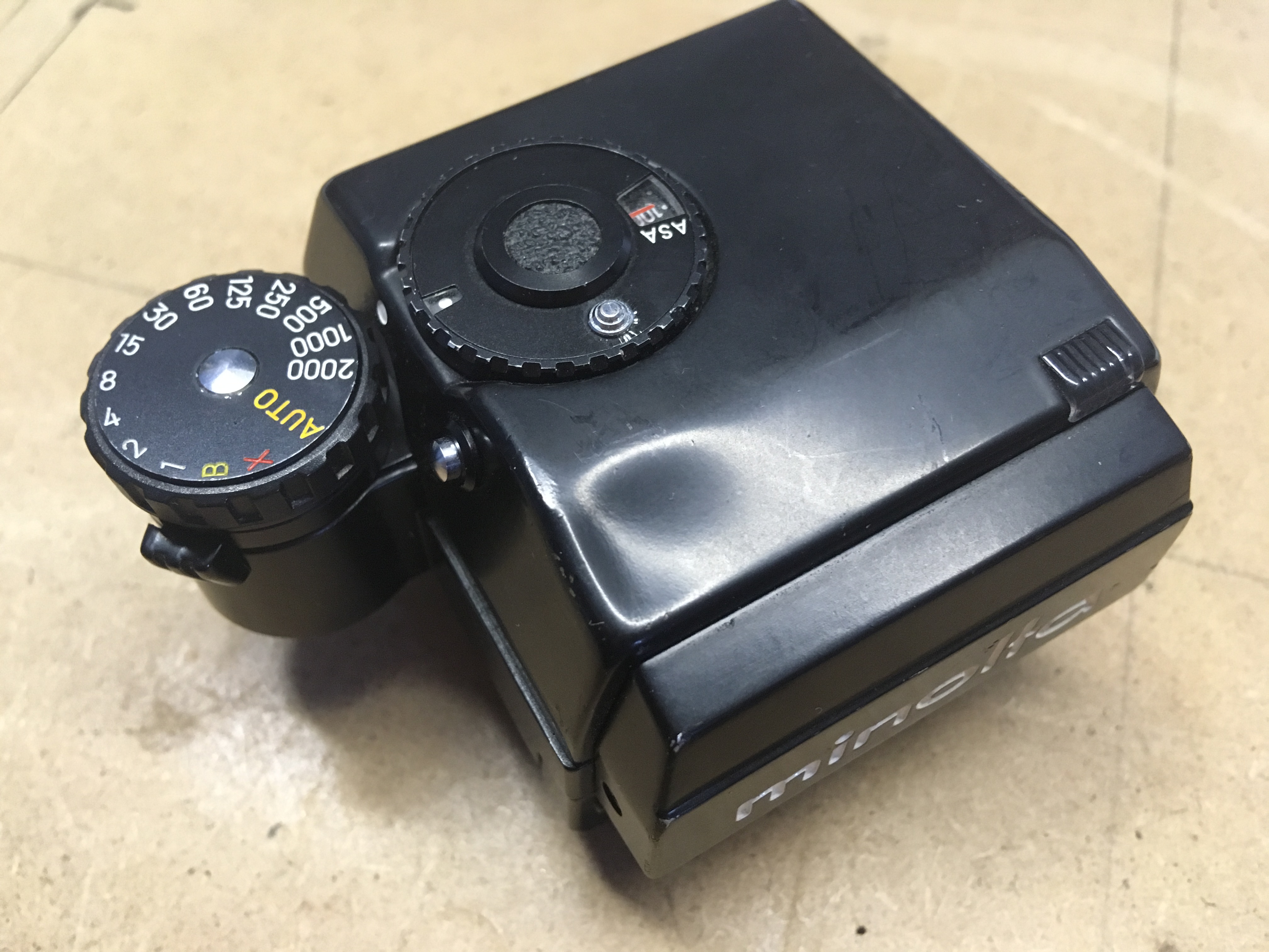
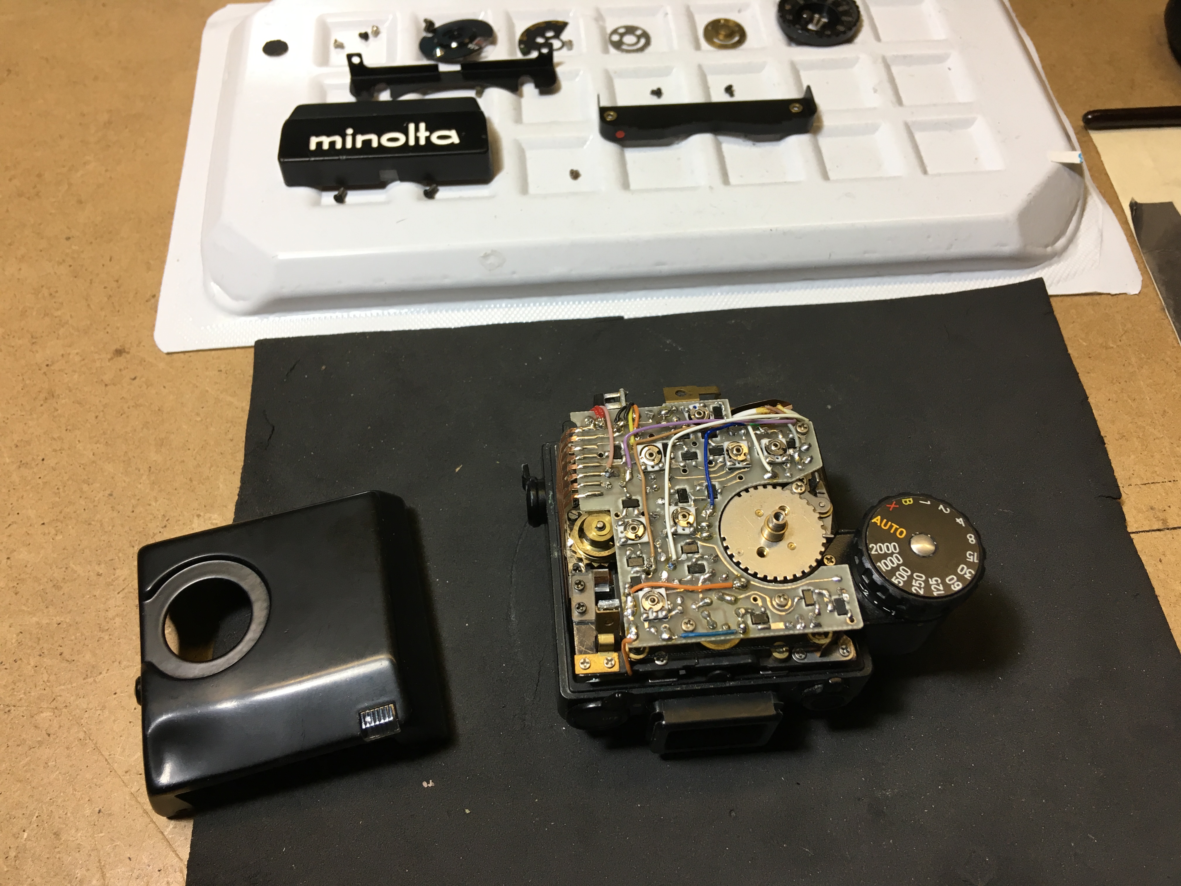
A Minolta AES viewfinder, rather desirable if not so dented! If it were only the dent, that would not be so bad, but usually other things have also suffered as a result of the bash that caused the dent in the first place. Let’s have a closer look ‘under the bonnet’…

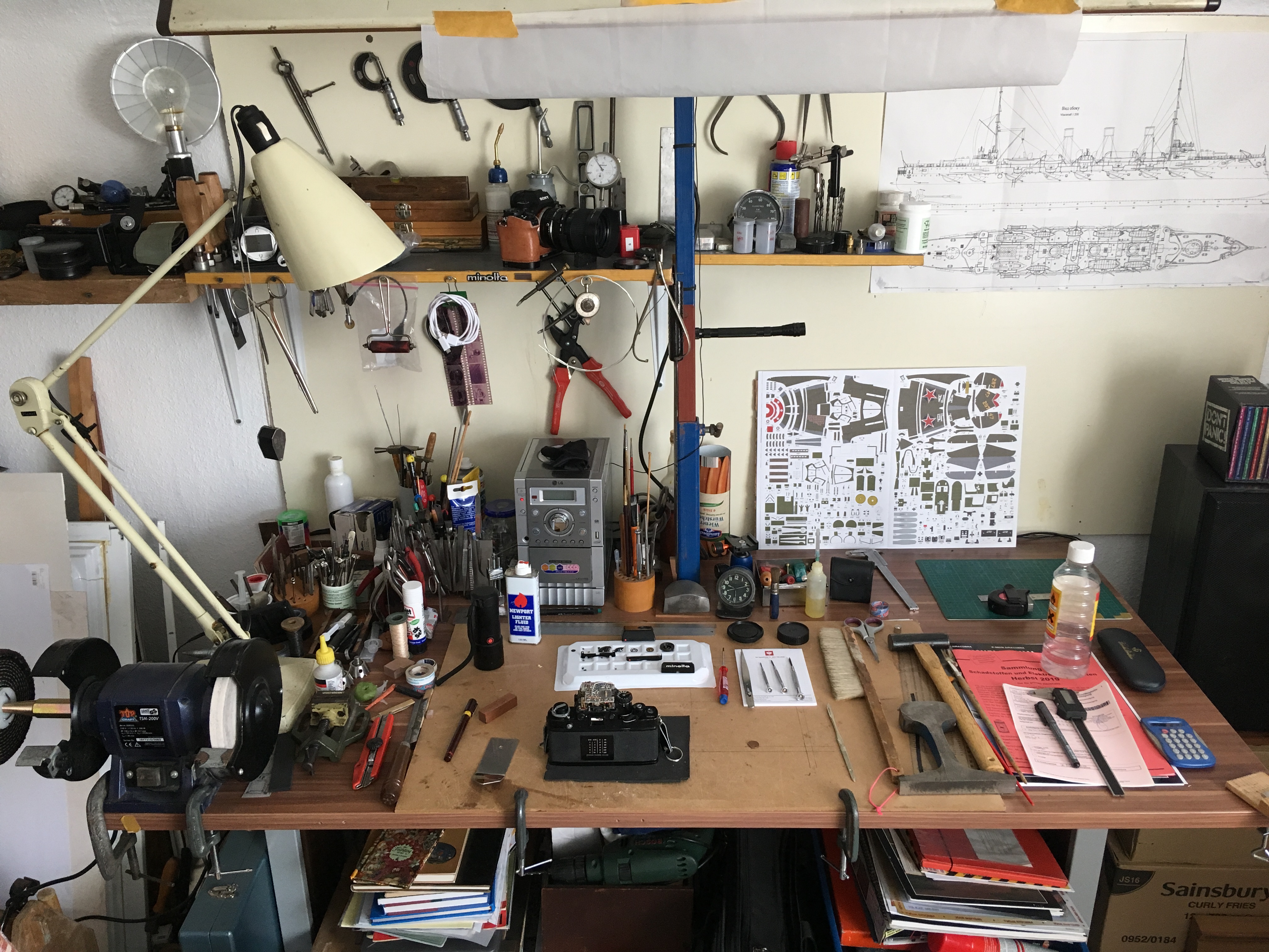
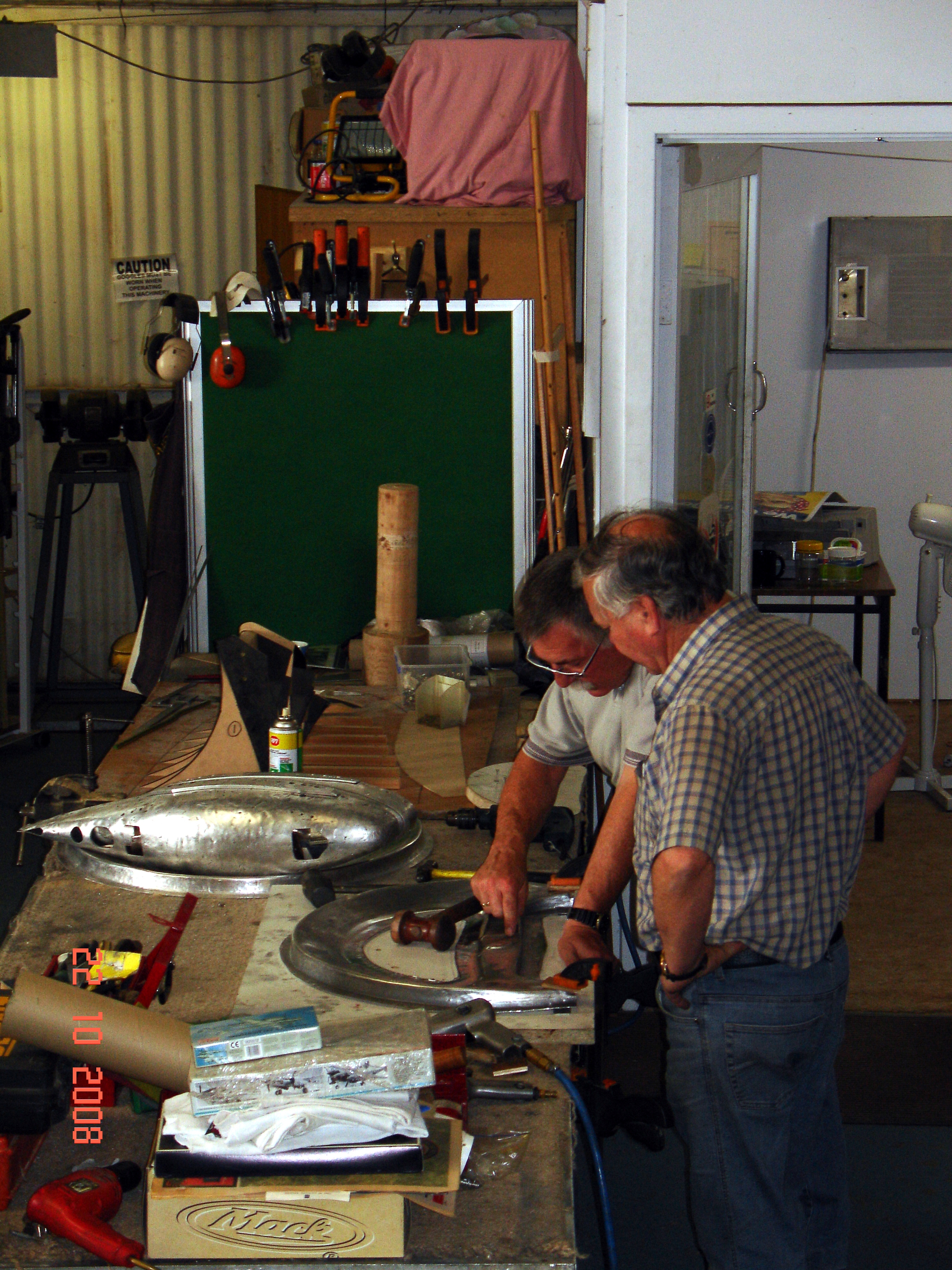
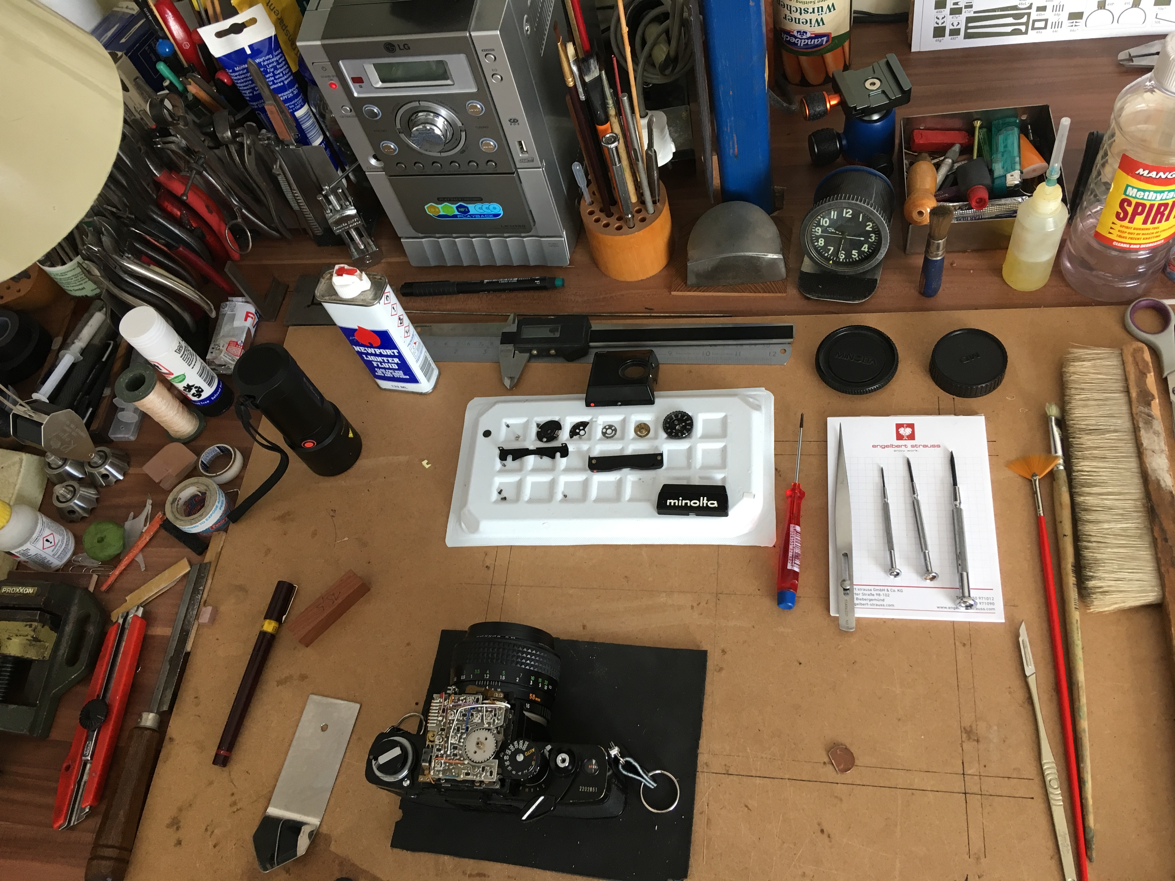
OK, this kind of space is all you need, so there is no excuse for not having a go yourself! Yes, I could have cleaned up before the photo, but it just goes to show the general arrangement. There are tools and materials for all sorts of tinkering and yes, while I’m actually working, there is more space around the working area as such.

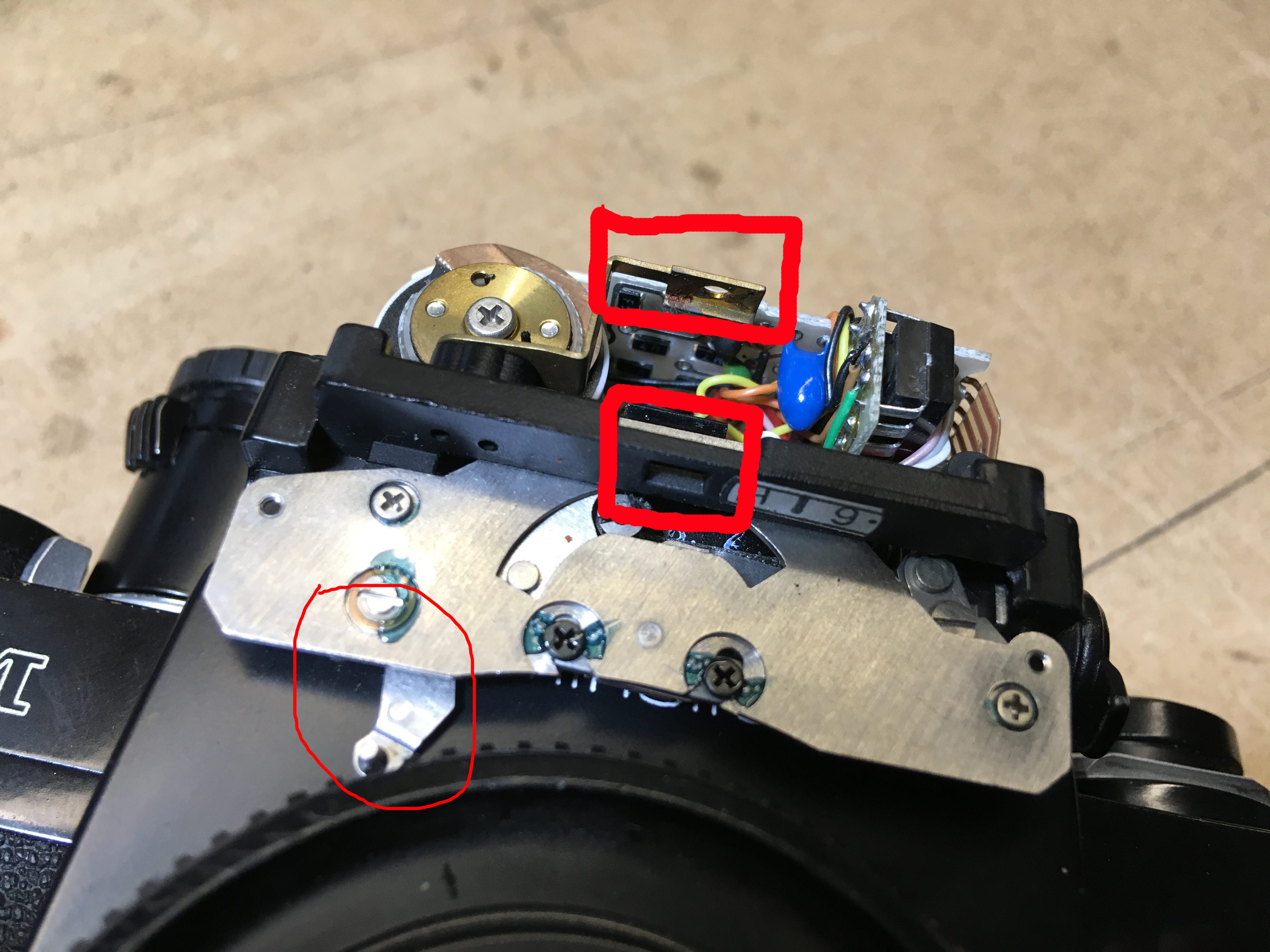
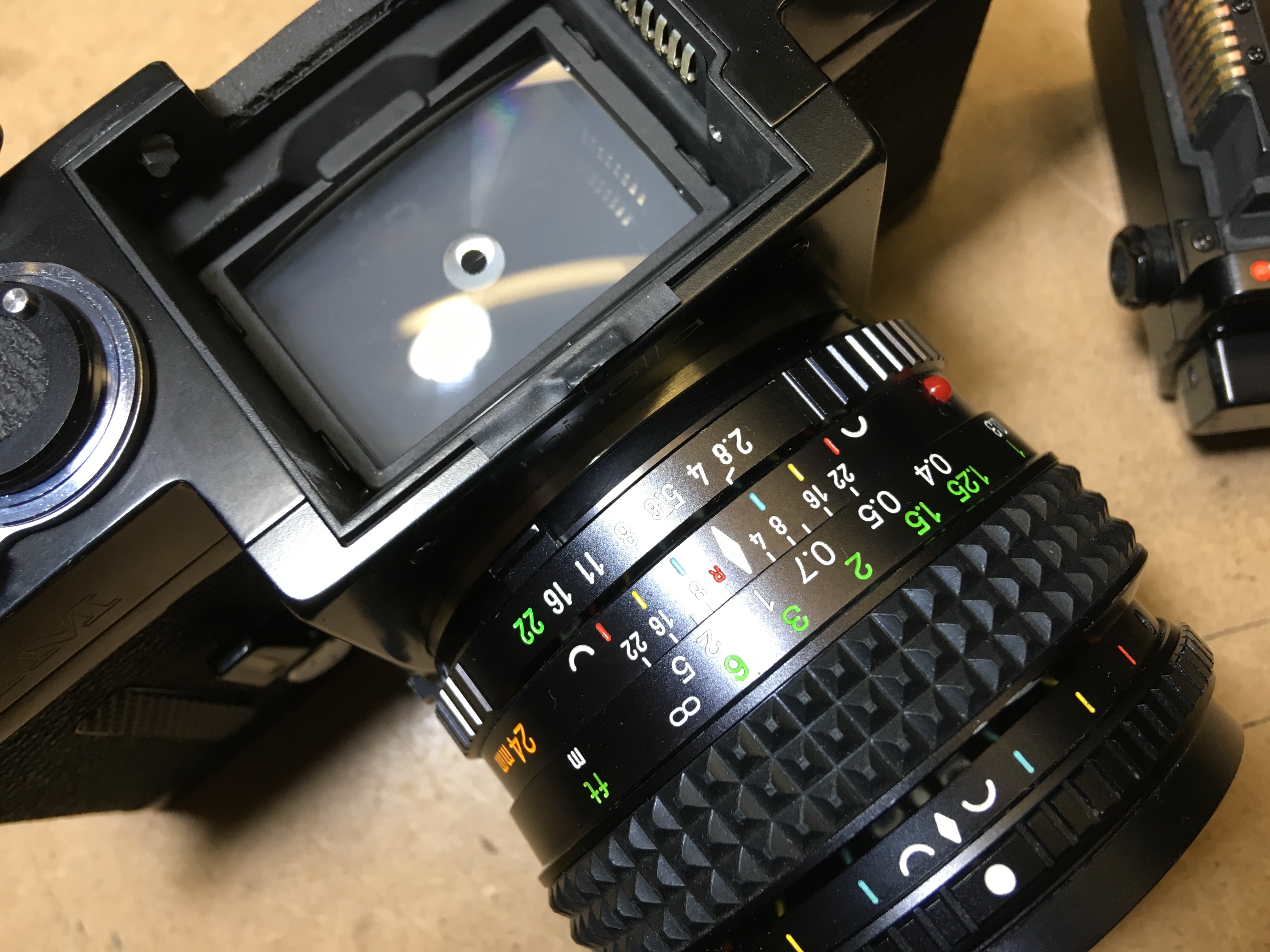
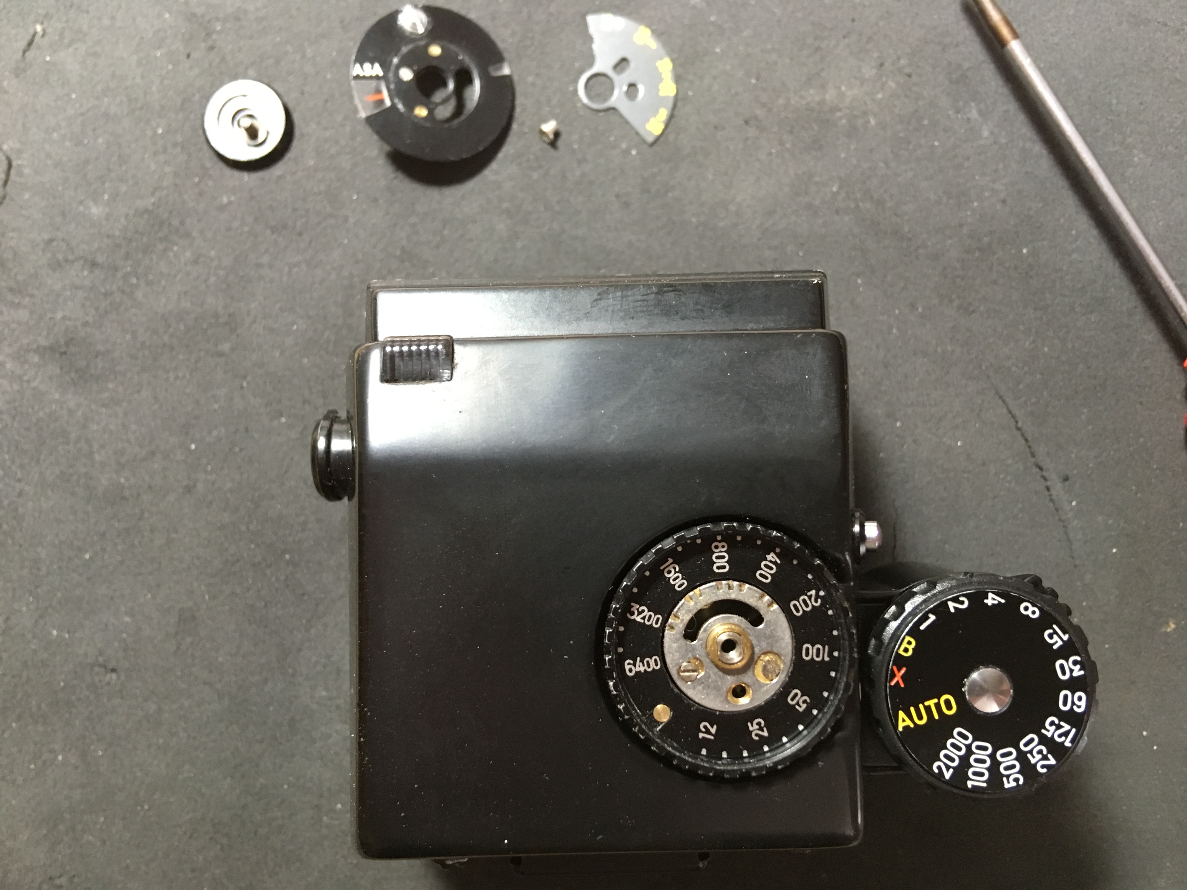
So, having taken the top off (easily enough done on this) it can be seen that the dent wasn’t all that was wrong: the mirror and lens which allow the numbers on the aperture-ring to show in the finder are gone! The thin red outline shows the aperture-link in the ‘normal’ position without a lens in place – more of that in a minute.

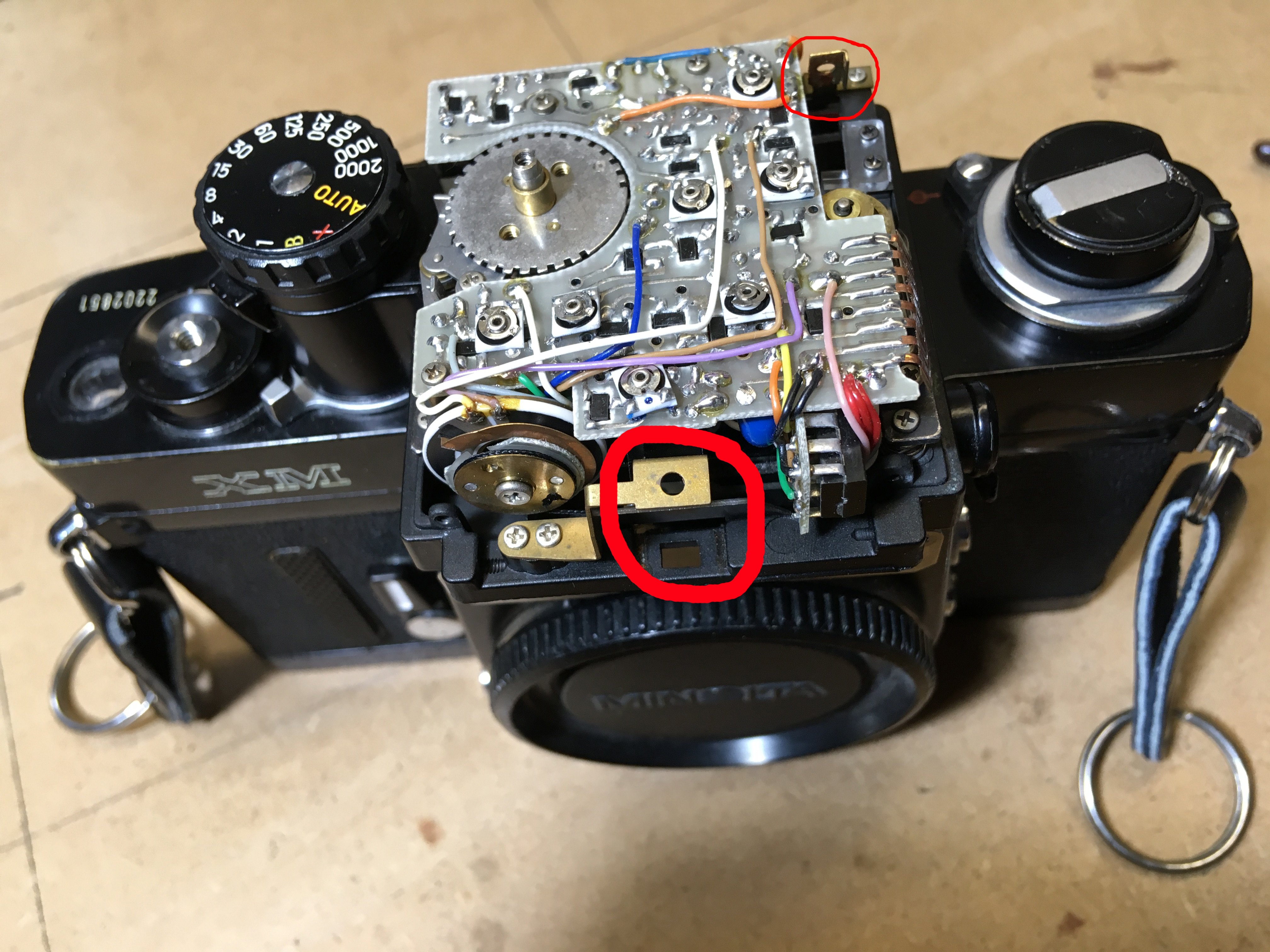
Here a clearer view from the top and at the back, the long mirror for the shutter-speed display is also missing, but thankfully had dropped inside and could be reduced in its proper place 🙂

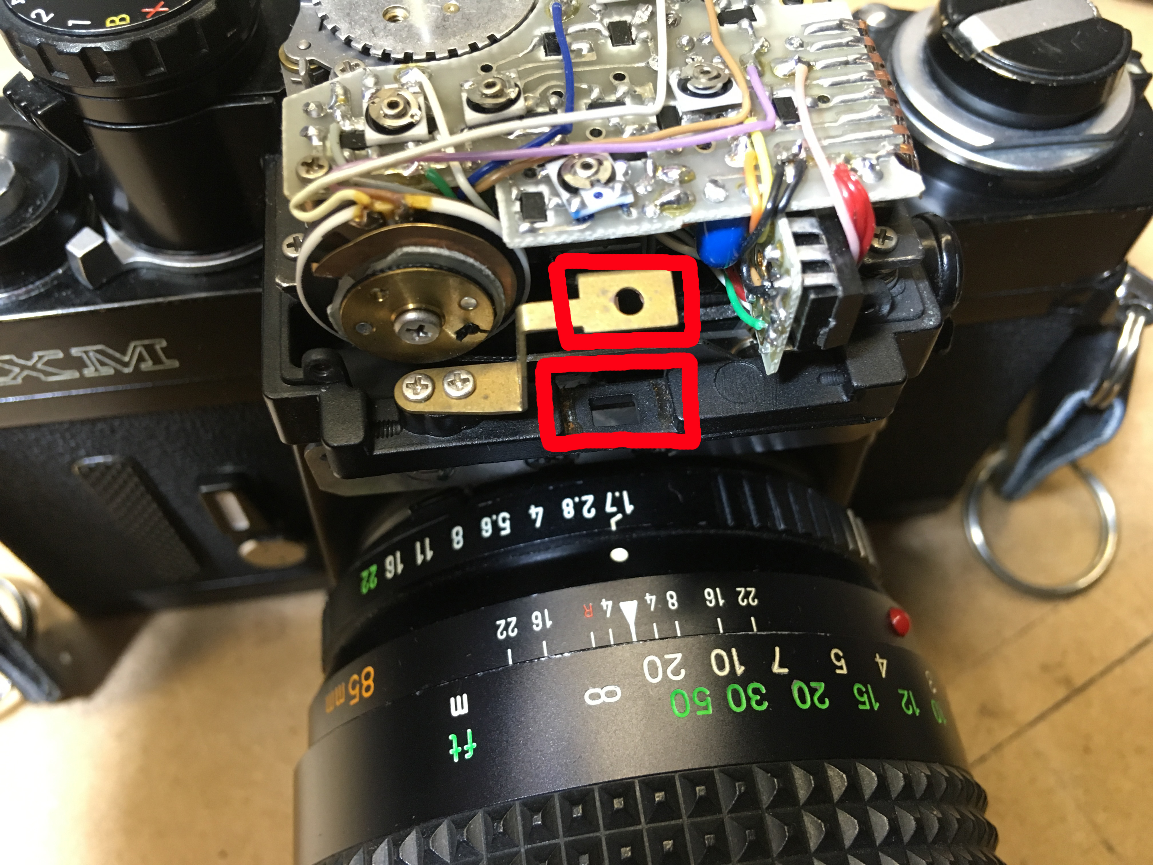
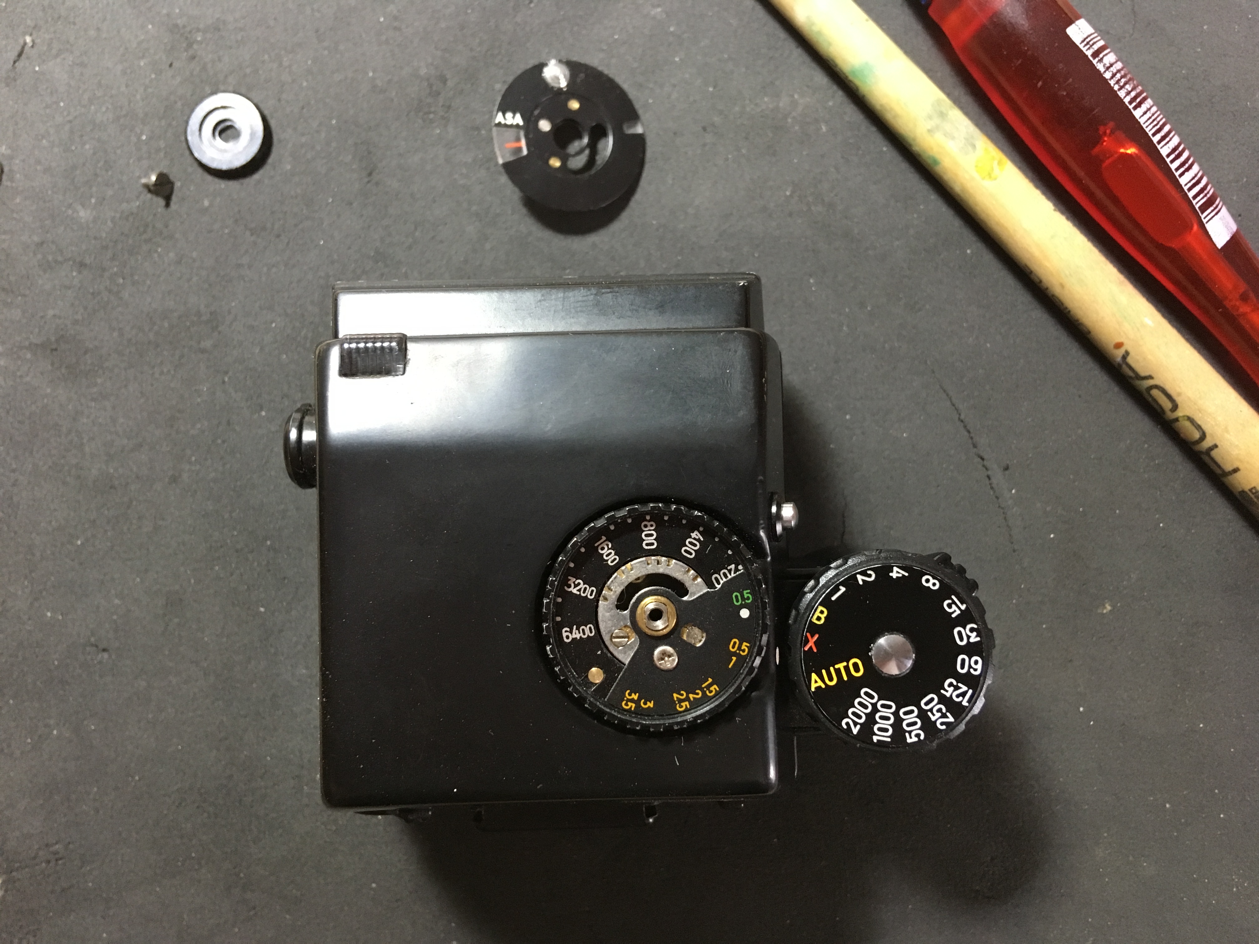
Here even more obvious, the REASON for what it missing and how it lines up with the lens ring. All I needed was to find a mirror and lens in my goodies-box and the case was solved. If I’m honest, a piece of 1mm thick polished Stainless would replace any missing mirror if you don’t have an original handy (the mirroring on these is on the FRONT surface, not on the back like a household mirror). For the lens, any one cut out of another Minolta SLR will do, even if you do have to trim it to size, it will do the same job since the distances of all finders from the lens-ring are very similar.

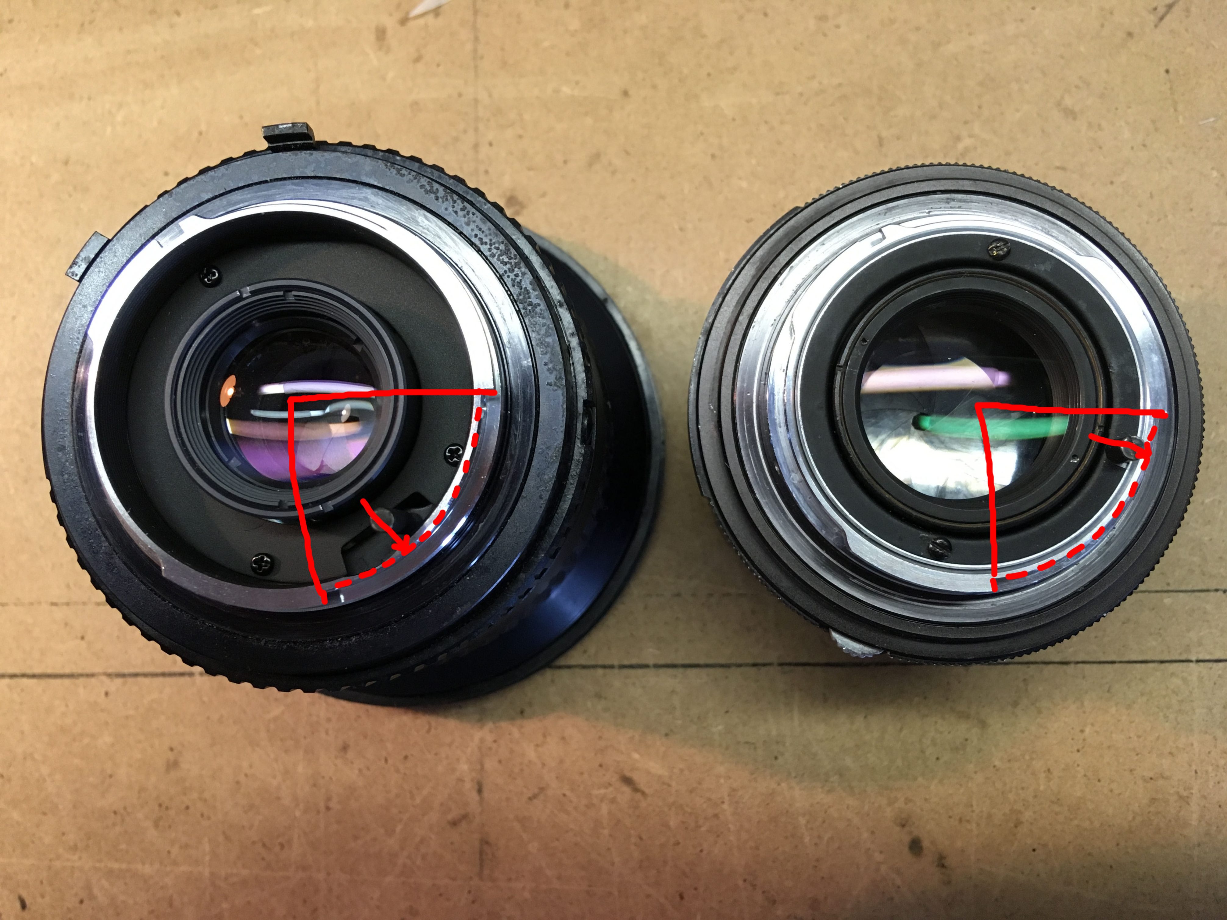
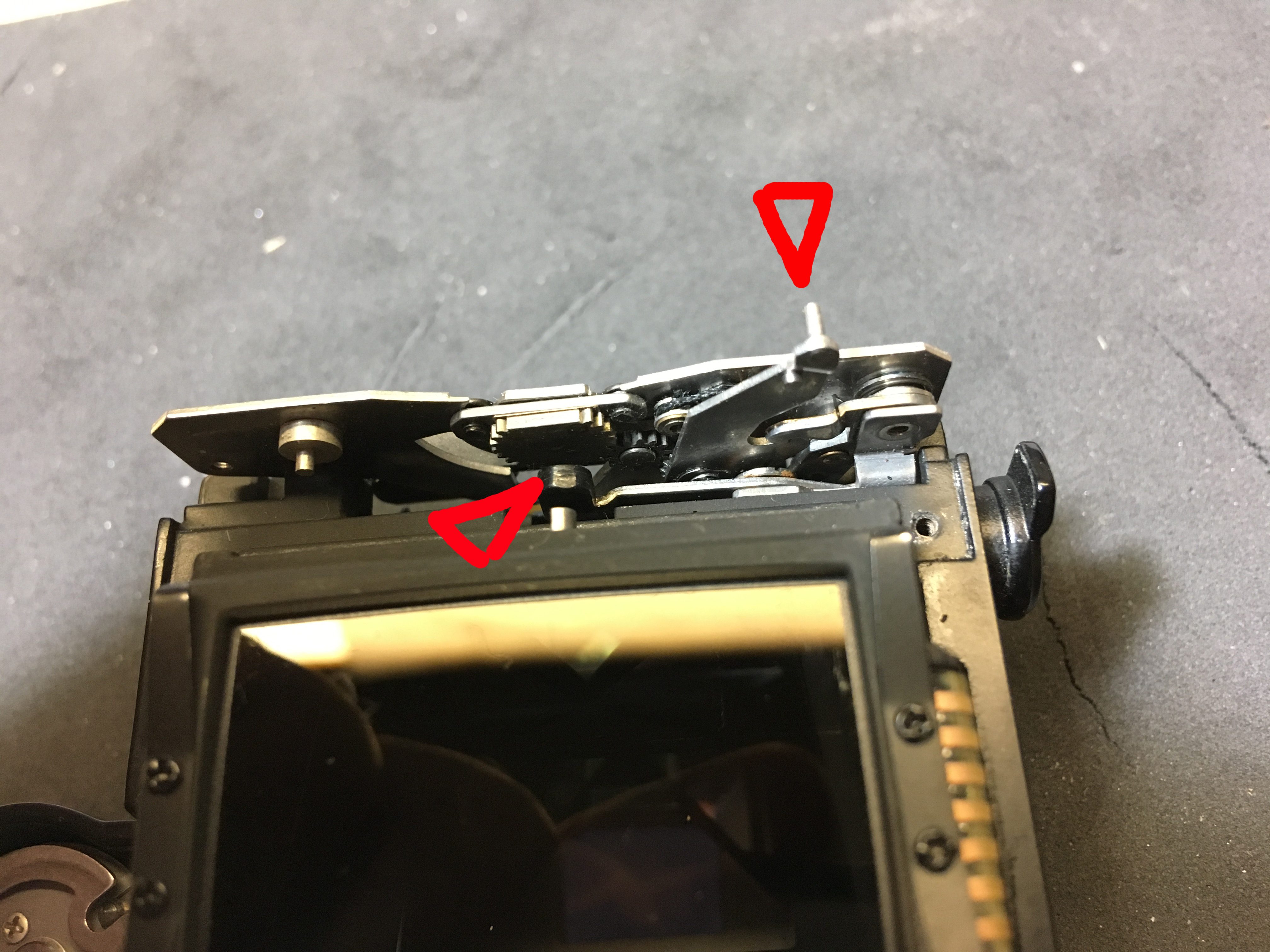
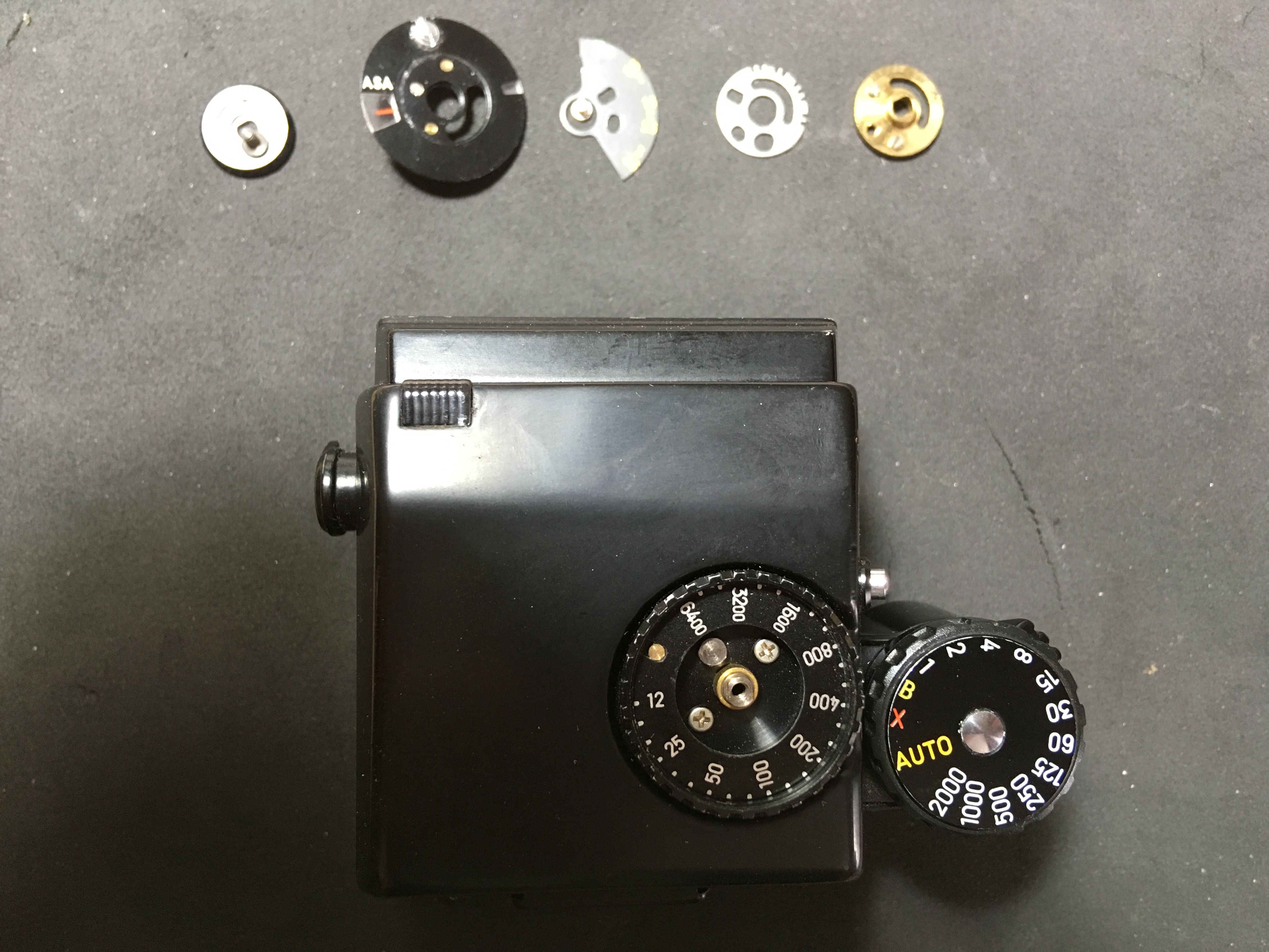
Below is a very different problem which afflicts almost every Minolta AES and AE viewfinder (not the others, since they don’t have metering). When the finder is removed, before replacing it the aperture ring follower has to be ‘cocked’, so that it snaps into the right place, should a lens be on the camera (in use that would be the norm). However, these cameras are a few years old now and have gone through the hands of many people, some salespersons, some of them photographers, some of them collectors and some of them without any knowledge of the workings of such things, from any of the above. This design was intended to save the camera being damaged by replacing the viewfinder with force and perhaps bending the linkages in the process. If you try to replace it ‘just like that’, you will notice that it doesn’t sit quite right at the front. Unfortunately, the uninitiated will just press harder until it clicks in place – the result of which can be seen below! The arrow on the right shows the follower correctly cocked on the right hand side and in the middle the release lever to reset it.

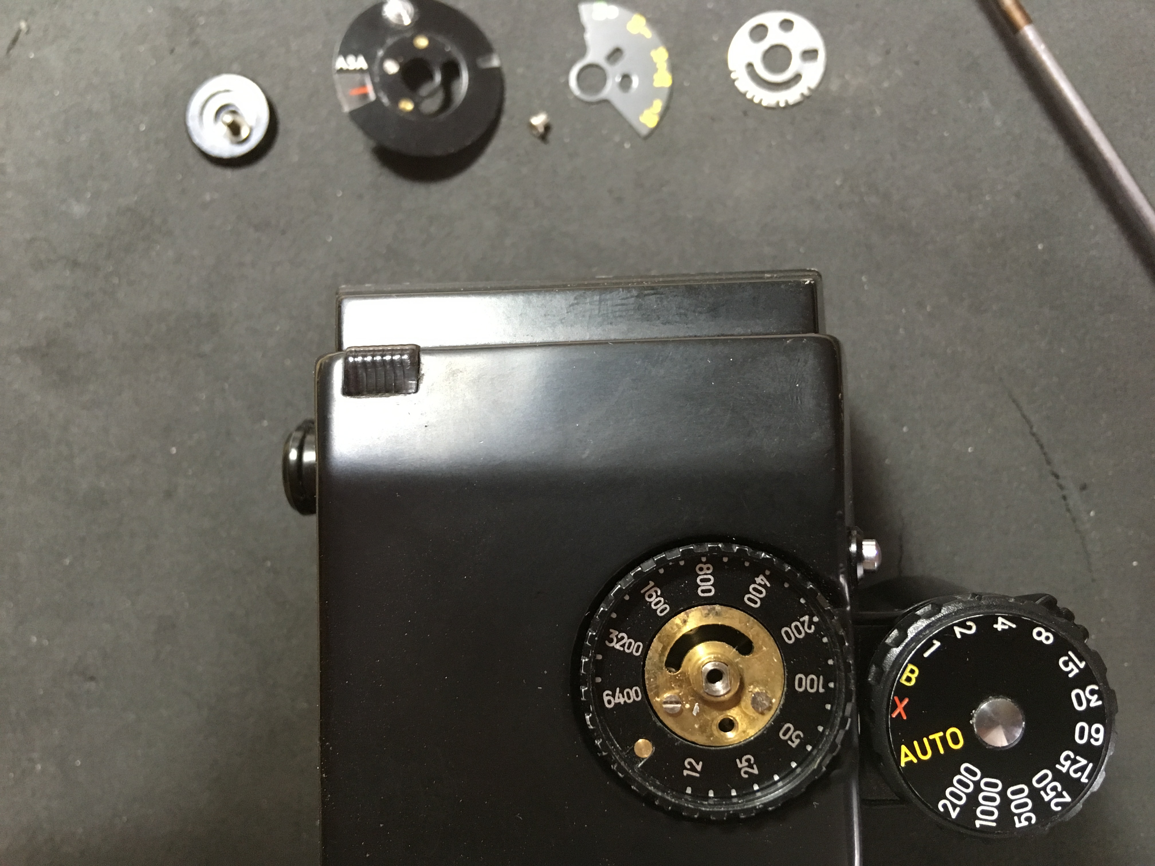
See the flat on the release lever? That comes from pushing the viewfinder down at the front until it clicks into place, as this lever, when the follower is not cocked, protrudes a bit as a reminder… of cocked properly, it retracts out of the way, of course.

So, who cares if it has a flat on it? Well, the user, actually, because having read the handbook and having cocked the lever properly, when the viewfinder goes back on, the follower doesn’t return to it’s proper place again and the metering is all haywire as a result!

The cure is to build up the front of the camera-frame, where the lever ‘lands’ with a strip of tape or whatever you have handy that it just thick enough to ‘trip’ the lever and something that does not permanently fix to the camera or damage it. Here I took a strip of cardboard and some insulating tape to fix it. It’s cheap and easy, works fine and doesn’t do any damage. Win-win! Don’t worry about light-leaks up here, the well is deep enough to shield any light that might come in – don’t forget, the eyepiece lets a lot more light into the prism.

Just a reminder of how the top looked like before. Suffice to say, I did a bit of persuasion with an appropriate piece of wood and repaired the dent without needing any touching up of the paint, which sticks like shit to an army blanket (ask anyone who has ever been a soldier).

You can’t see it here, but once the mirrors etc. have been replaced, the next step is re-assembly, which is pretty straightforward. Working from right to left in reverse order of disassembly.


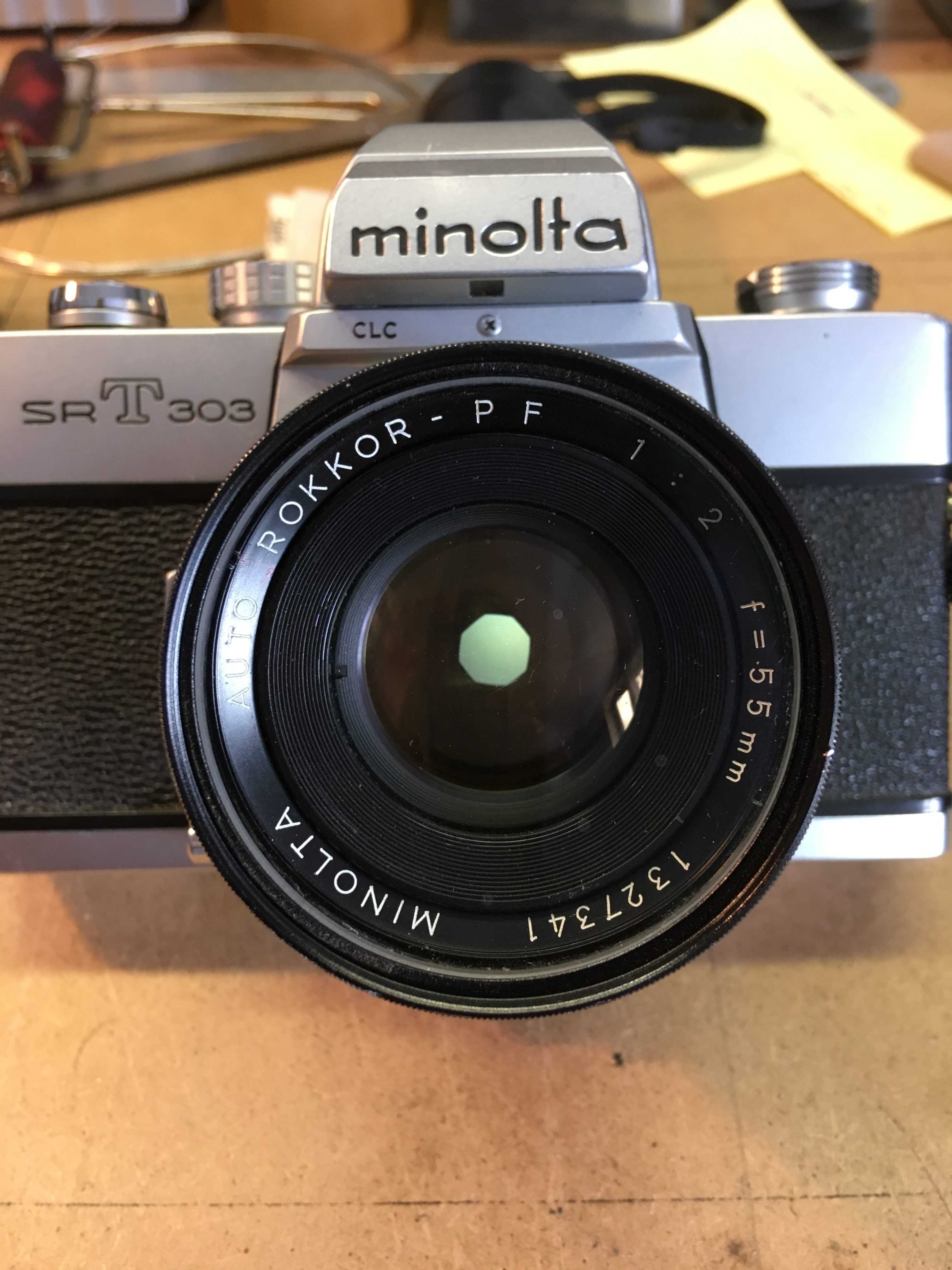
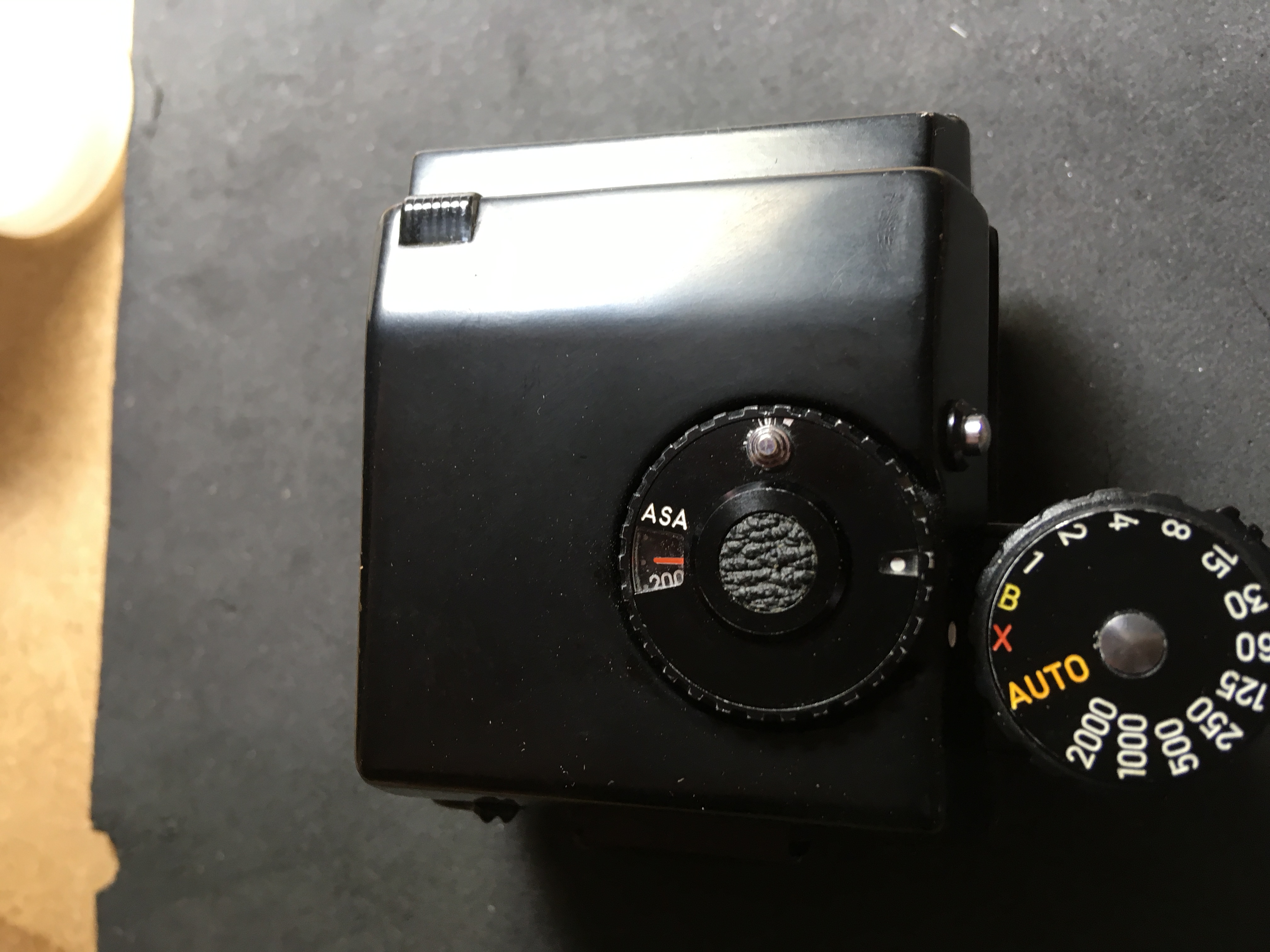
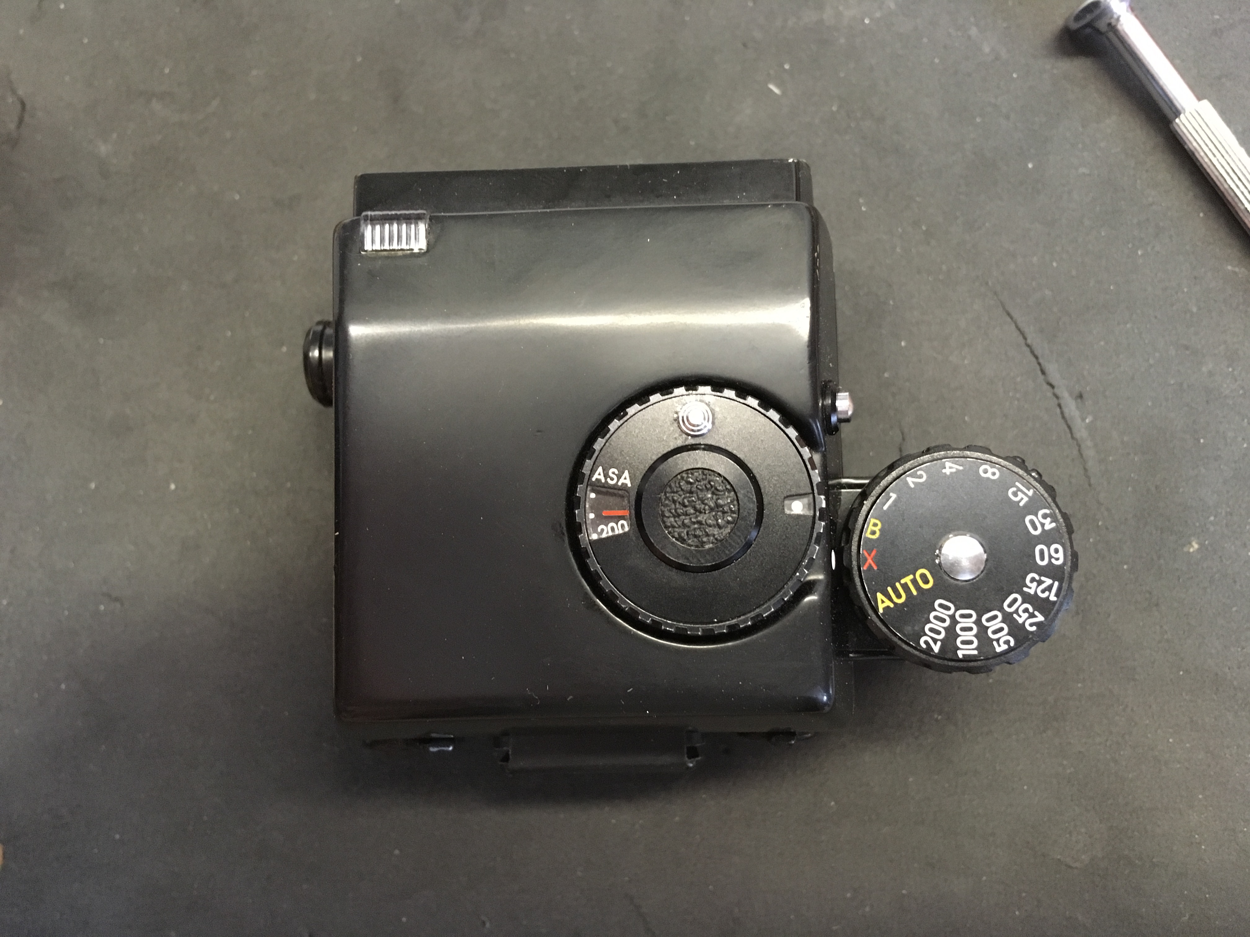
Finally assembled with ISO 160 showing here and ready to go! All adjustments and cross-checks of the mechanics and metering were also done while the lid was off, of course.

The repair to the top is acceptable, I think.

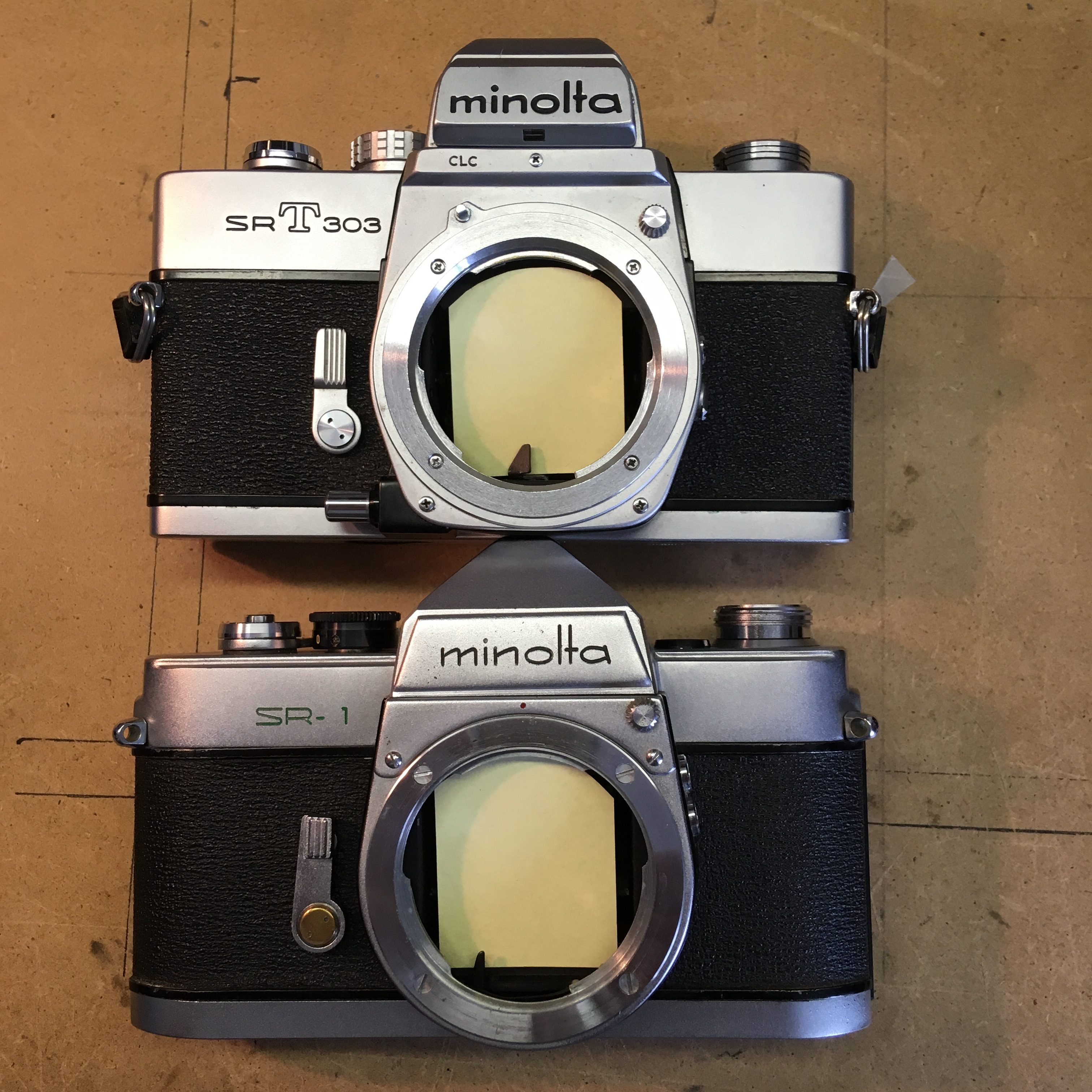
Next up for discussion? The comparison of two very early 100mm F3.5 lenses an AR1 and an AR2 (by the way, one of Minoltas best-kept secrets, an inexplicably underrated razor-sharp lens). Construction, mount, iris, size and weight are different… Though they look very similar, until you have them up close 🙂


P-39 Airacobra Restoration

For those interested in Aviation, warbirds and the modelling of the aforementioned, here are a few pictures I took while working on the Airacobra in Australia at the ‘Classic Jets’ Museum at Parafield Airport in South Australia. Actually the busiest airport in the whole of Australia, mainly due to it’s being the home of a number of flying schools, including one used for flight training of quite a few large airlines, Parafield is also home to a number of classic ‘fly-ins’ and the Museum, of course, where almost all the work is done by volunteers. I worked on a few aircraft, but this is the one I spent most time working on.

Here a couple of views inside the workshop hangar.

Gives a general idea of things. The RAAF Airacobra in question in the background. Here are a few pics of the instruments and cockpit as it goes together:

And here a closer view of few of some of the individual instruments:


Lots of engine-details for the modelling enthusiast. These pictures are big, just click on them for larger, click again for super-size! Not much chance to see one of these up close, though used for many aircraft. Carburettor at the top and induction charger below it, the (shiny!) induction manifold on the top of the engine between the ‘V’. The pic on the top left shows it in the initial stages of build. As we progress it gets ‘smarter’ 🙂


The pictures below are of the other, running, engine in the public hangar which was originally out of a P40, which is why it has the reduction gear on the front, unlike the P39, which had it installed just behing the propeller and spinner, of course, fed by the propshaft which ran between the pilot;s legs… Makes quite a racket in the hangar and we converted it to run on Gas, as when on Avgas, the open carburettor spat flames to the roof on a cold start… 🙂

Here a few official pictures of the engine from Allinson themselves:


Here some detail pictures of the armament and ammo-boxes being built for up front. Ours didn’t have guns in the wings. Two machine-guns synchronised through the prop and a cannon shooting through the centre of the spinner. Convenient that the reduction gearbox, mounted on the front-most bulkhead had a hollow spindle! Drive from the prop-shaft enters at the bottom of the reduction-gear casting and the actual drive to the prop is a larger gear above it, allowing plenty of space for the ‘shooter’.

The rearmost, larger but narrower, munitions-boxes are for the machine-guns, the wider curved rails are for the larger (and fewer) cannon-shells:

Here how it is set up in the ‘plane still in primer:


Not in primer anymore and fitted up in TG*R !

And finally finished and mounted : (this one in Victoria, another A/C, another museum) The red box is a battery! More weight up front, critical for the distribution of weight and balance necessary to fly the aircraft. The mid-engine made it more maneuverable, but more sensitive to weight distribution. Cannon-shells fitted, MC Ammo-boxes not yet.

Here a few pics of some work I did on a pair of rearmost wing-fillets. We had one original on loan to copy and I had to make up left and right copies, hence the reversible template. The finished items were made slightly large all round for final ‘fitting’:


Here the aircraft ready and finished for the Parafield Airport Vintage Fly-In in 2009

Minolta SR lenses NOT the same as MC/MD

OK, So everywhere we see the ads, mostly on eBay, where Minolta SR lenses (the ones called Auto Rokkor, with ‘W’ for wide or ‘Tele’ added on) are broadly equated to MD-Fit or something similar. Beware! This is not necessarily so!  The very early lenses do FIT ON the Minolta Bayonet, but DO NOT STOP DOWN to their minimum aperture. This has physical reasons, which I shall explain.

This means that the first series of these lenses attach correctly (the Minolta bayonet stayed the same until Auto-Focus came along) BUT the lenses only stop down on the later cameras to an aperture of around f8, no matter what you pre-set on the lens. This is due to the placement of the lever inside the cameras and lenses, that are, to put it simply, in different places! From f8 upwards in the direction of ‘more open’ I have found no limits and the restriction does NOT apply to fitting to Digital cameras with adapters that anyway don’t stop down, which is great news.

Take a look why: I have taken shots of an early SR1 (‘b’ series) from 1960 and compared it to the mount on the SRT* (in this case a 303) when the ‘MC’ notation was introduced. Note the placement of the lever at the bottom of the mount, that closes the lens down at exposure.

Firstly here, the back of an SRT/MC/MD Mount lens on the left compared with the early SR (Auto Rokkor without the MC/MD) mount lens on the right. You will note the difference in the placement of the Iris-Lever, although both are stopped down to f22. What you can’t see, is the range of travel of the lever for the lens on the right, which is almost the whole arc as drawn in. compared to the tiddly bit which is obvious in comparison on the left lens (physically limited by the slot it can move in axially – less than half of the arc); on the later Auto Rokkor lenses, from about 1960, the stop-down lever for the iris is the same as for the MC lenses operating from inside a ‘window’ and will work perfectly on later cameras – definitely any camera made after 1961.

Below the positions of the actuating levers inside the back of the mount on the cameras themselves can be seen. The SRT 303 is representative in its proportions of ALL manual Minolta mounts from then up until the introduction of the Auto Focus mount.

In this picture, the lens would be STOPPED DOWN, on the SRT using the button on the side of the mount and on this early SR (1959) by simply not cocking the shutter – fully automatic diaphragm came in 1961 when both the SR3 and SR1 got the modification. The difference in the position at maximum deflection is pretty obvious.

The same two cameras when the aperture is held open: Actually identical.

Here we have both cameras with the lens mounted and stopped down to f22. I think the difference speaks for itself. The picture speaks a thousand words?

The SRT manages just smaller than f8. This will happen to ALL early Auto Rokkor lenses if mounted on SRT and later cameras (actually any Minolta after at the latest 1961, when the automatic diaphragm was introduced). The other way around, ANY Manual lens will work correctly on the earlier, pre-SRT cameras and of course with any of the Digitals, too – with an adapter.

So, it’s up to you, but buying the earlier lenses, with very few exceptions, is not better than a comparable MC or MD, despite being cheaper (mostly). Quite apart from the mentioned deficit in the usability on later cameras, for the most part the performance and definitely the coatings just doesn’t make it worthwhile – unless you have the very much earlier cameras! The thing to look out for to positively identify the first series of lenses is the flat ring on the back of the lens without the ‘window’ for the iris-coupling, as clearly shown in the pictures above. Another indicator, if not definitive, is the aperture-ring with the engraved yellow ‘LV’ values below the f-numbers. Some, however, even with these engravings also had the later mechanism 🙂 The thing to look for is the evenness of the aperture engravings (if they look ‘wonky’ then they probably have the long travel) and the back of the lens, of course. If the pin sticks out of a narrow window, then you are fine. Watch out for lenses over 100mm, they might be long-travel AND have a window for the pin: the length of the window will give it away.

The SR-2 and both ‘a’ (first series with ‘lift-up’ shutter-speed dial) and ‘b’ versions of the SR-1 without the meter block all have the long-travel lever, but in 1960 alongside the introduction of the SR-3, there was also a ‘plain’ SR-1 (‘c’) without the block, but with the automatic diaphragm…