How it works

Building card-model ‘Diana’ by Dom Bumagi

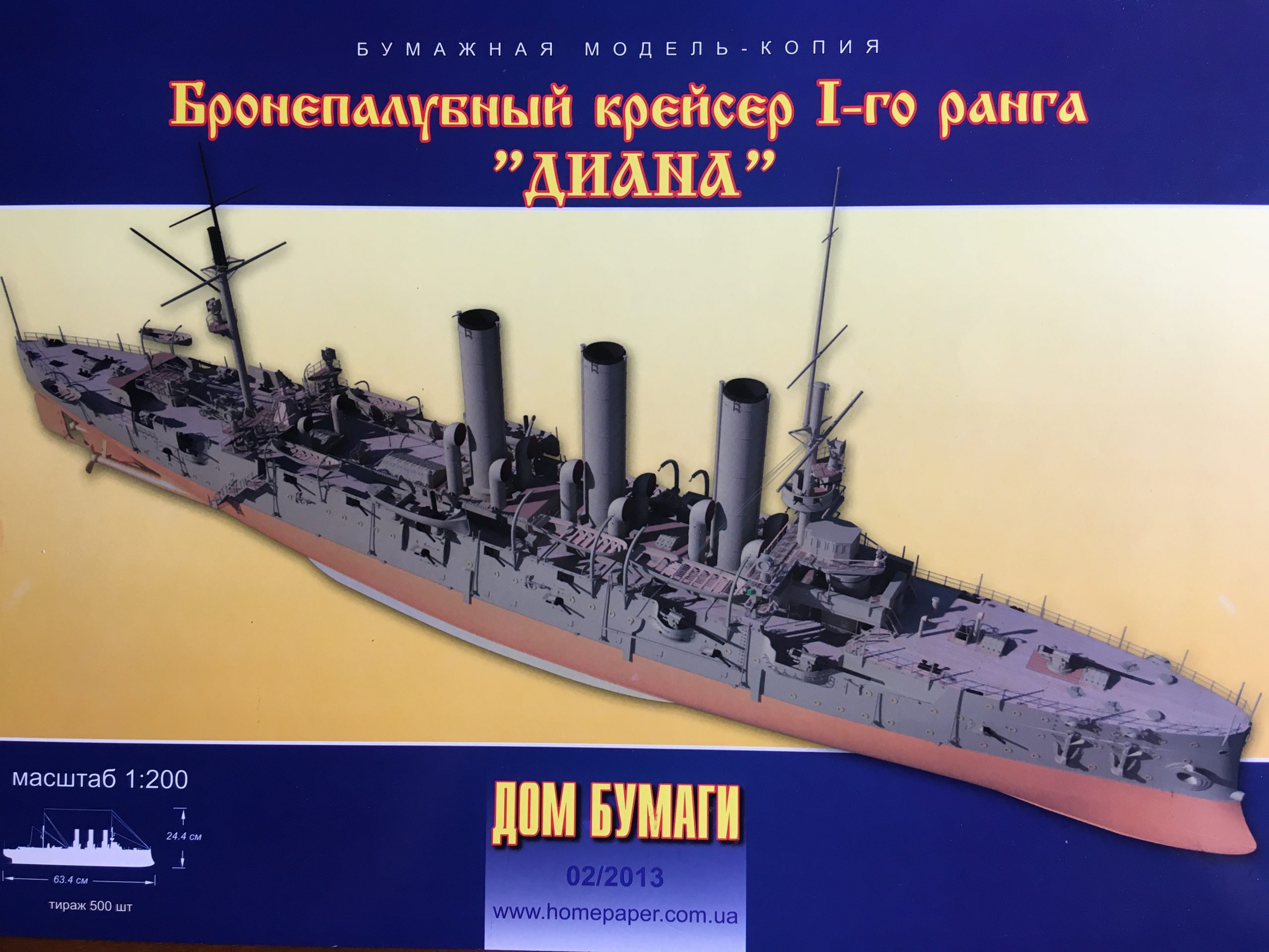
I decided to get back into paper modelling at last and chose to start the ‘Diana’, which I bought while living in Ukraine in 2015. I have a number of (unmade!) models of the Pallada class In 1:200, the other ones are all of the Aurora depicted in different build years and by different companies, Polish, Russian and now this, Ukrainian, one.

Looks very impressive and I have not yet built one of their ‘super-detailed’ models, so here goes!

This is actually only my second warship in paper, my first having been the Ark Royal by ‘Maly Modelarz’ probably twelve years ago… a very satisfying build and an impressive display piece, despite its comparative simplicity. That one was stolen (!) during a break-in in 2010. I did have a go at another Russian ship of the line, Bogatyr, but that was damaged badly during the build and had to be scrapped last year 🙁 Up until now I had built quite a few aircraft, which made very pleasing models (but take up a lot of space ) and so I started a  sailing ship , the ‘Coureur’ – still work in progress and the SMS Götzen, which is undergoing a conversion to it’s present livery and build state as still used in Africa.

Regarding the Diana, I’ll skip the history etc and go straight to the model.

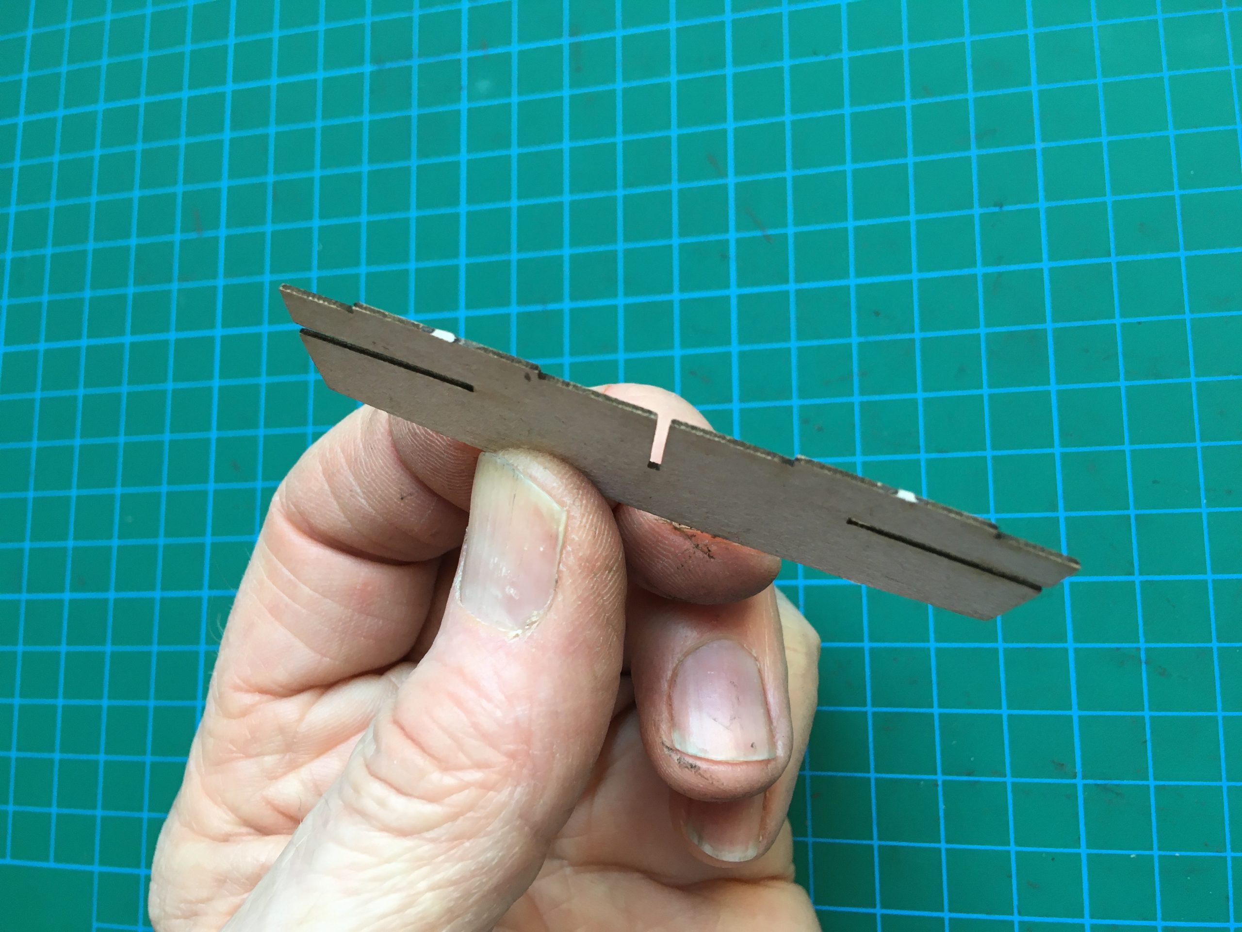
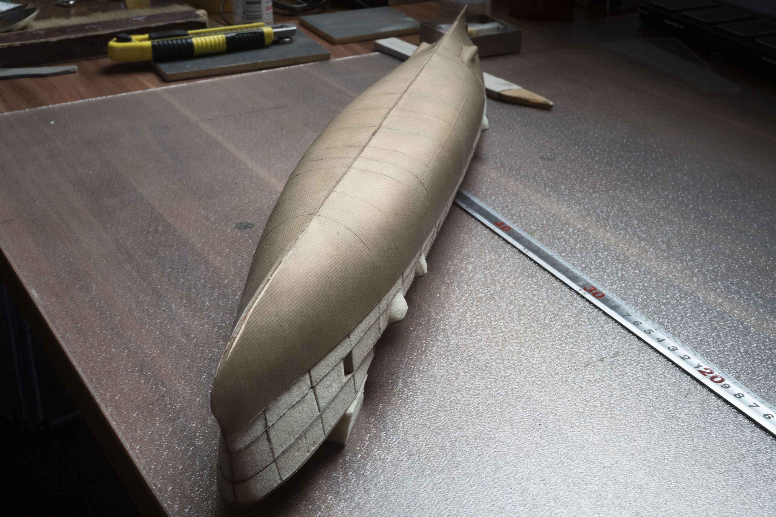
I decided to buy the laser-cut frames to save time. Nice is that it can be built either as a waterline model or complete with the hull below the waterline. I didn’t think to compare the laser-cut to those printed As templates in the sheets, I’ll definitely do it the next time, though. The reason I say that is, the width of the laser-cut profiles for the hull below the water-line was wider than the parts for the upper half. Not by a lot, but definitely so. A little less than 0.3mm all round, which is thicker than the card for the hull covering, which will leave an unsightly step? This also means probable trouble fitting the top half of the model? The frames fitted nicely together and were unproblematical, bottom and top halves being made separately, checking them regularly for squareness.

Each individual part of the frames is trimmed and sanded prior to assembly after cutting free, so there are no ‘nibs’ sticking out where they were cut from the card carrier-frame, which would possibly distort or ‘grow’ the assembly unwittingly.

Having glued them up and left them to dry, I filled the hollow frame of the hull with a new material I wanted to try out, but which it turned out is very messy (it leaves a fine dust which sticks to everythingand is too soft. Can’t even remember what it is called, but it was used at the wharf for coring out the reinforcements in the hulls. I shan’t be using it again. Below, you can see that the left hand side is finished and the right is not! It is also visible that it is subject to crushing and therefore difficult to glue.

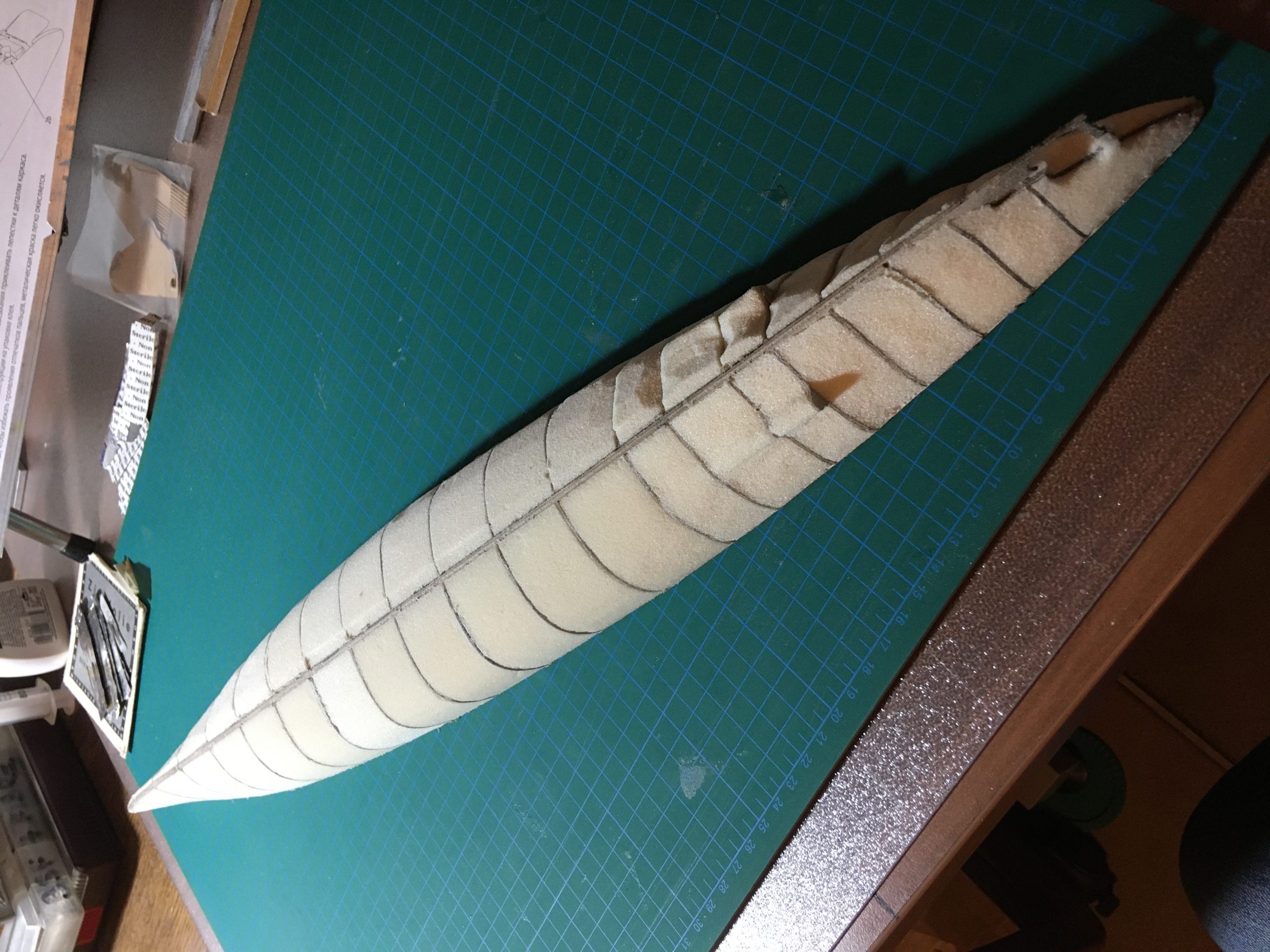
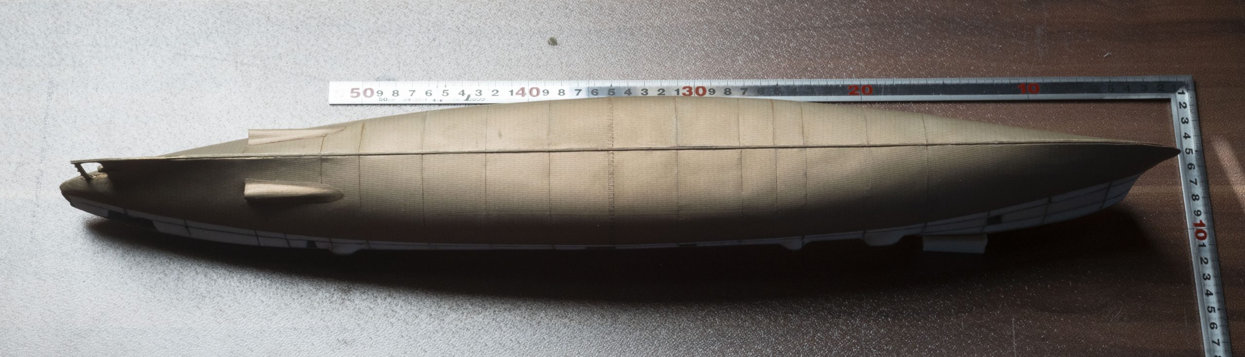
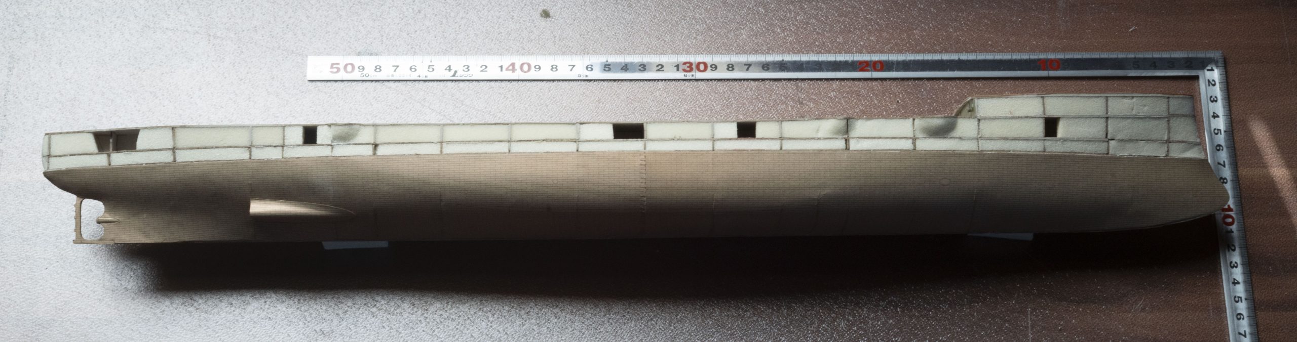
After sanding the hull to shape, I then filled out the upper half above the waterline (NOT sanding it to shape yet), glued the upper and lower parts together put it all aside to dry and settle:

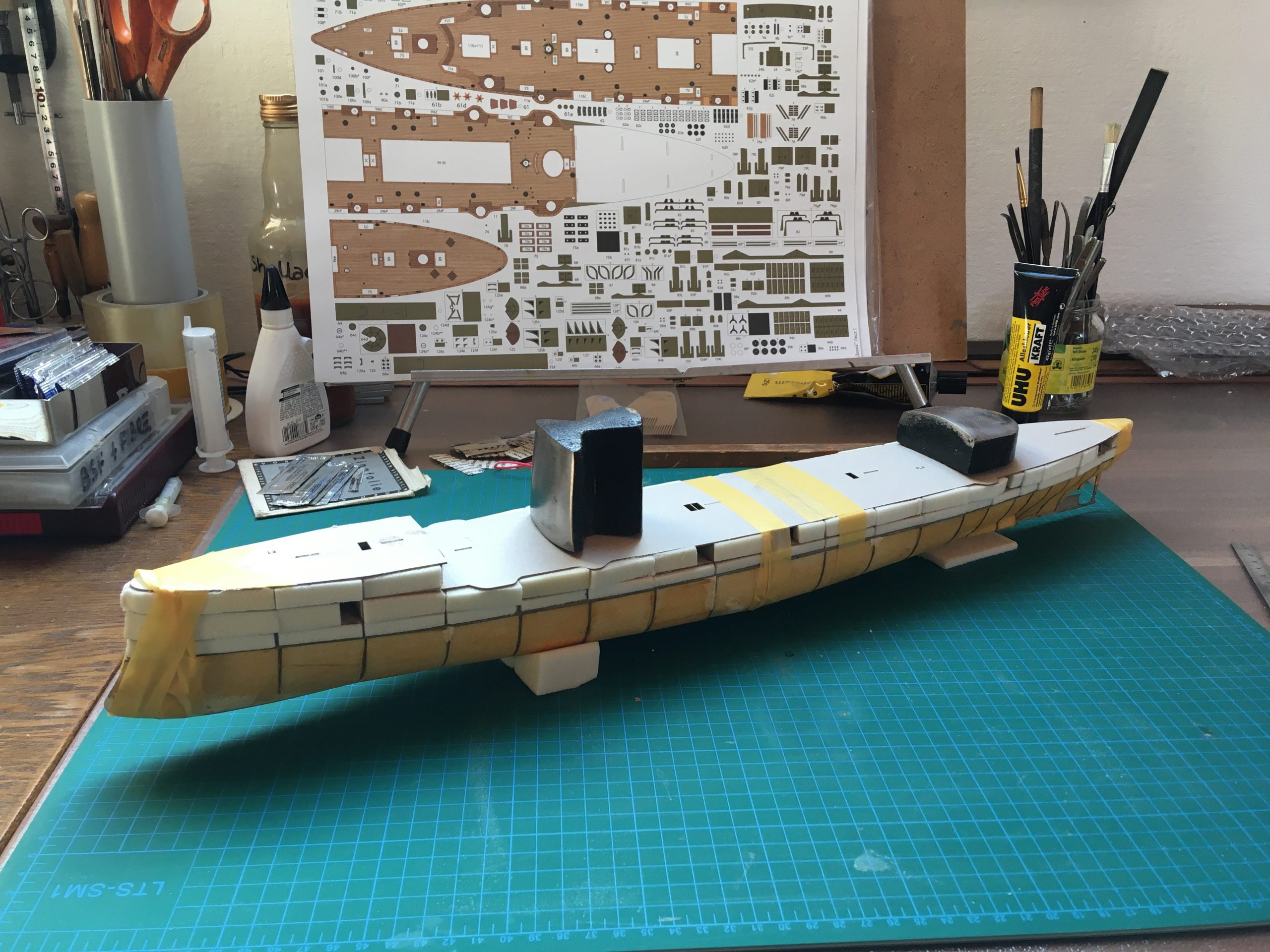
The next stage is the ‘copper’ hull: Not perfect, but doesn’t look bad either 🙂

For the full report, please go to https://thingummybob.com/modelmaking/building-dom-bumagis-diana/


Minolta RF Rokkor 500mm f8 sunshade

Well, I don’t know about you, but the pitiful length of the sunshade on both mirror lenses I have owned have always disappointed me… I realise that the coatings on these lenses are nothing short of wonderful, but especially mirror lenses are very sensitive not only to vibration, but also to adverse light conditions. So I thought I’d do a test. I made up a sunshade out of card and tested how far I could go without vignetting on the 500mm shown here. Believe me, I was surprised! The whole inch of the original sunshade was well under a sixth of the shade I built WITHOUT any sign of vignetting. I don’t think that anything shorter than the diameter of the front lens is useful or that anything much longer has any actual added benefit (I’m willing to be corrected on this), so I decided to improvise myself and use ‘easily available resources’ (i.e. without resource to a lathe) to make a usable and effective sunshade. Originally a little tongue-in-cheek, the finished product works wonderfully, was really cheap to make and is light and can store all sorts of stuff – even a lens – inside it in the camera-bag! Win-Win 🙂

The diameter of the lens makes it unusual, so getting one from another lens was out of the question. Looking around the house, I found a consumables tin that fit actually very nicely and also had he benefit of a plastic lid that would be handy as a lens cap! Originally filled with nuts bought from a supermarket (the same size is currently available here for the equivalent of £2.50), I carefully removed the bottom with a cutter and pressed/rolled the ragged inside edges flat with a cross-head screwdriver blade (anything metal or hardwood would do the trick) and put some ‘zebra’ tape (paper, actually) on the inside to stop it scratching the paint on my beloved lens… 🙂 At this stage, the functional work has been done, as it now slide-fits snugly over the front of the lens including the original sunshade and butts up nicely against the barrel, without being loose. I then decided that rather than spraying it matte black on the inside, that I would line it with black rubber foam sheet available at almost all supermarkets in their craft department in various colours. A strip 44mm wide is perfect, as it fits exactly from the front to where the original sunshade is and gives extra ‘Register’ there, to hold it nice and snug.
Look at the photos to convince yourselves of the fit and function – regarding the optics of the outside, perhaps you will decide for yourselves what is more appropriate. I went for a cover of thin, black leather, but matte black spray paint, card or anything else will do according to your taste; you could even leave it as it is (as I have for months!) or do a pink fur and Smarotzi-Diamond job on it! Enjoy!


To be honest, even the Original cap fits (as seen on the photo above), but the original for the tin is of course a perfect fit.

You May also have spotted another ‘modification’ that I have for this lens to take the light input down a stop, without having to swap filters in the back! I converted it to an f11 lens with a ring of the same foam rubber sheet as above (formerly tested with black card) which is cut to fit nicely under its own tension in the front of the lens. No glue, just fits nicely and doesn’t fall out an can so easily be removed or replaced, doesn’t get damaged or damage anything and doesn’t take up any space either! The doughnut-ring Bokeh ist thinner, of course, but for a quick and dirty solution, this works nicely. I can’t claim that the depth-of-field is influenced to any degree, though. Still, it does offer a bit more than just one ND4 in a pinch!

The case on the Sony is also one of my handmade additions, too, by the way. The top will be completed soon, too!

Here is the budget sunshade as finished and used at present: I could have used black thread, but, “what the hell”, I thought… 🙂

Dr. Peter is a frequent contributor to thingummybob.com

Minolta SR Slow Speed governor checkup

Hallo SR Fans! Ever wondered where the slow speeds (less than 1/15th) are clockworked? Like most other mechanical movements that are past their ‘sell-by-date’ (in this case nearly 60 years out of guarantee!), the works are often glued up or just plain sticky. The oils and greases after so long turn to sticky goo and don’t do the intended job anymore.

With this particular camera, as with many others, a good clean with lighter fuel is all that is needed to keep things running smoothly for many years to come without any lubrication. Let’s face it, how often do you use shutter speeds of ⅛ or less in general – or the self-timer, for that matter, unless you are needing the slow speeds, of course… For macro work, for example?

Nevertheless, it is annoying when they don’t work on an otherwise usable camera, so here is a quick fix for those who are interested:

The clockwork for the low-speeds are under this cover; hold the mirror up and be careful when undoing the screws, as they are not very ‘deep’ and you are going at them at an angle, because the prism housing and lens-mount are sort of in the way 🙂 The paint scratches easily and you don’t want anything bright or reflective in there!

This is what it looks like under the cover and is where the buzzing comes from:

Upright the camera when rinsing out with lighter-fuel (as in this pic), please and then cock the shutter and release a few times at each speed, until it sounds right. Don’t be be tempted to add oil, it really isn’t necessary. Any traces of old oil will pool where it is needed through capillary action and be left when the fuel evaporates. If it sticks again in ten or twenty years, you now know where to fix it! 🙂

l recently received an SR-2 that behaved strangely: The shutter seemed oddly stuck, but somehow released, but left the mirror up… One shutter blind worked, but the other just stayed put. What was the problem? When I took the front plate off, I found the shutter blind completely wrapped and stuck to itself. Melted, actually! Some over-zealous previous owner had diligently removed the top cover and ‘cleaned’ the works by pouring acetone over it… No problem for the metal parts, but what dropped through onto the roller-blind fused it together for keeps! So, please remember, use a fine artist’s brush to apply fuel/cleaner or a very thin Pipette, so that you can control where it goes 🙂

This is what greeted me inside:

Minolta SR-2 vs SR-1 comparison

Ever wondered what the real internal differences are between Minolta‘s first SLRs? First pic is of an SR-2 stripped of the ‘leather’, top and bottom plates off and my high-tech protection for the mirror box internals. The front plate with the mount and self-timer has not yet been removed.

SR-1 partially dismantled, but with the front mount section already off and the self-timer no longer fitted. Notice the difference between the castings and the ‘SRC’ in relief on the front next the mount: on the SR-2 there is not any such marking.

Here I’ll give a short look inside to still your curiosity (and mine!). So the SR-2 was the first in late 1958 and is put next to an SR-1 from around 1961, the ‘c’-version; the last one before the change was made to the aperture automatic. Two quite different mechanicals altogether, despite looking very similar, especially the bottom end, where the aperture and shutter actuation takes place.

Optically, the early and later models are relatively easy to tell apart if you know what to look for.. all the 1959 models have a much smaller eyepiece on the back, which is not so easy to spot at a glance. Easier to notice is the shutter-speed knob on the really early ones (the SR-1, too) that needed to be lifted to change the shutter-speed. On the top the scale is not quite evenly distributed, the 250, 500 and 1000 look evenly spaced, but they do have a little white line engraved to show the actual position needed to dial in those three speeds. From the front, the early dial is more conical in shape, wider at the bottom and smaller in diameter on the top than the later model (there is about a 2mm gap to the winder-lever). The later one, as you can see, is more straight from the side, and is as a result larger on top and has evenly spaced engravings up to 500, without the extra lines. The earliest SR-1 shutter-speed dial was similar in shape and size to the SE-2, missing the top speed, of course. There follows a series of photos showing some of the the external and the internal differences. Later I will show the internals of the first SR-1 model, but the differences between these two models are more obvious 🙂 The picture below shows the SRC on the casting rather more plainly.

There are, of course, lots of detail differences, that are too many to mention here, but worth mentioning and visible in this shot, is the mirror-fixing with screws, rather than the riveted-on mirror in the SR-2 🙂 There are also subtle differences between the self-timers, not only the front casting which they are mounted to: The one on the bottom or the right in this picture is off the SR-2 and fits behind the oblong brass plate. It also has an extra large flat screw (taken off on this picture below, but visible later once mounted) on the front side and the teeth on the spring-gear (the largest one) look like they have been ground or worn down… look closely at the pictures and you will see what I mean! The difference in the gear is plain to see.

SR-2 with the sellotape and here the differences in the gear-teeth are more obvious on this one. Note also that the backing plates are not the same, though the mechanisms are largely interchangeable:

Here the SR-2 self-timer is fitted and the large screw which is no longer on the later models at the front is rather obvious. The screw behind it on later ones is also significantly thicker (see pictures above).


Below shows the shutter-release mechanism in the base which is distributed half-half between topside and bottom. Most jamming can/must be sorted down here, the shutter speeds are controlled on topside. The lead-wires are for the flash synch and every camera seems to have them differently routed, depending on the wishes of the assembler! Here the difference in the size and shape of the tripod-mount is also visible, along with the completely different mechanical layout… few interchangeable parts here!

A look at the base plates shows that both are also different, as the mechanism on the SR-1 needs a cut-out at front (behind the lens-mount) to accommodate it – in preparation for the following model. At this stage, they both still have the long-travel aperture lever. the hole for the tripod-thread is also larger on the baseplate of the later body.

Well, that wraps it up for today. I will sort out the orientation of the pictures when I get home… I wrote this on my phone and it won’t let me do everything I want to!