Uncategorized

War in Ukraine

Due to the current situation in Ukraine, I have other priorities than posting my irrelevant rubbish here.

My dear wife’s whole family are stuck out there, in Khmelnytskyi, Kyiv and Kharkiv, so two of the cities right in the middle of all the troubles. We keep in touch as much as possible, but that will be more and more difficult as time goes on, assuming that they remain alive. Her mum and dad are in relative safety (so far), her 17-year old nephew is studying in Kyiv and her brother is 45 and has to serve in the military now. God only knows where.

I also have many close contacts from my time out there who are now being split up as families and the men being sent to fight.

I shall refrain from airing my opinions of the World response (and lack of foresight/preparation/hindrance of the situation), any more than to say that I am disgusted at their burying their heads in the sand/looking the other way, when they all knew exactly what is and has been going on for at least since 2014.

God bless and protect those in the Ukraine and the rest of the world when – and I choose my words carefully – when the situation inevitably boils over into Europe and the rest of the world.

Diana large davits Part 2

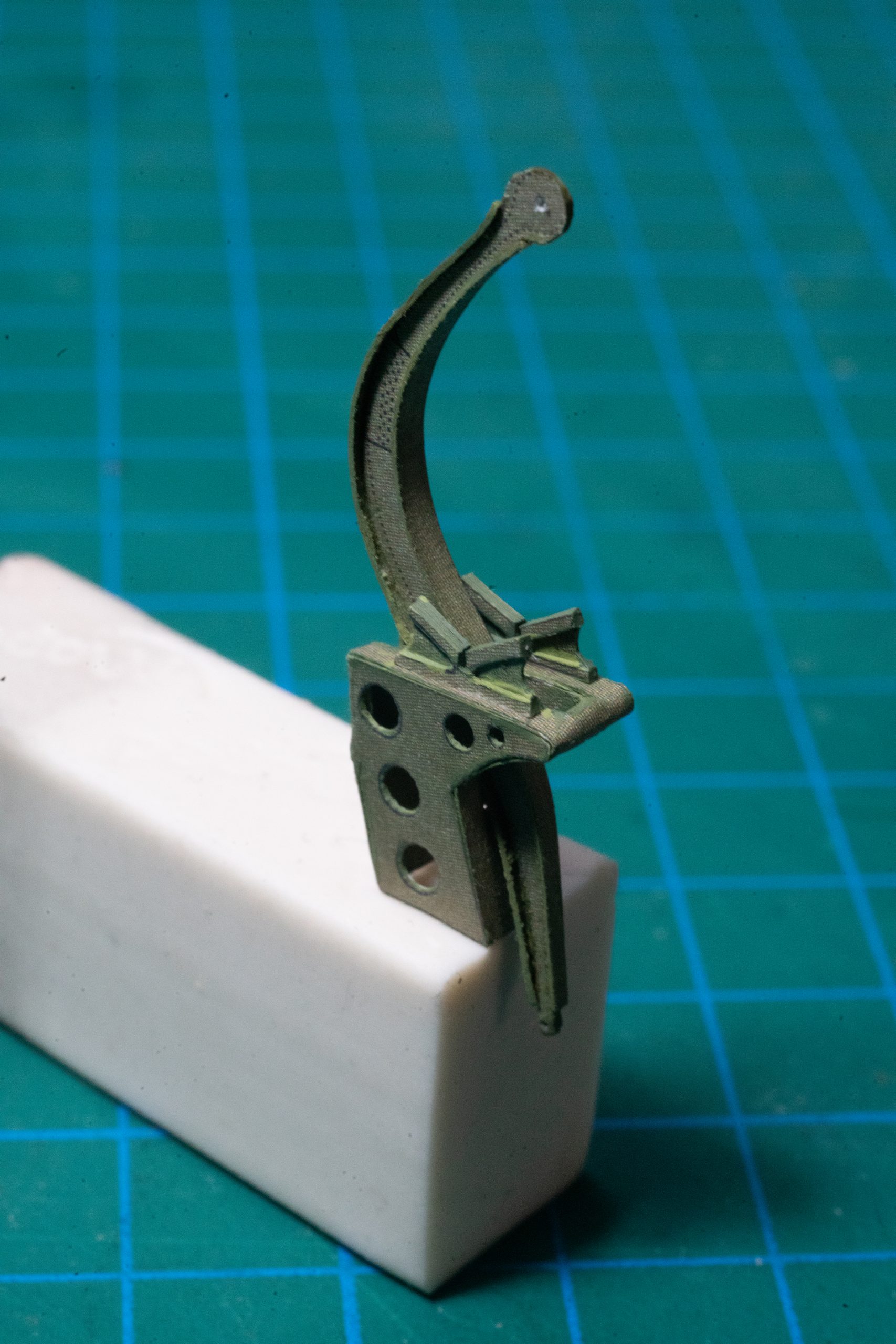
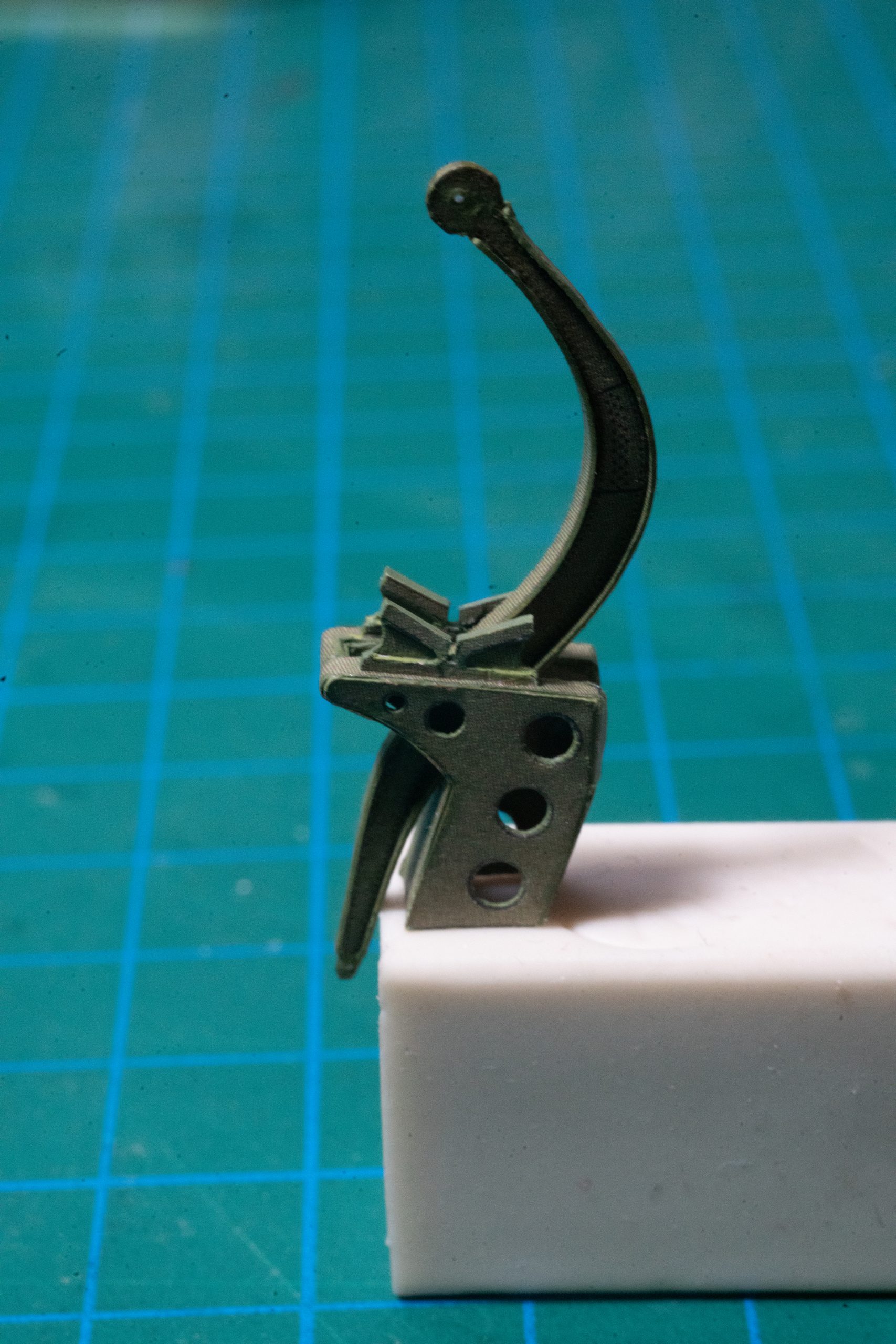
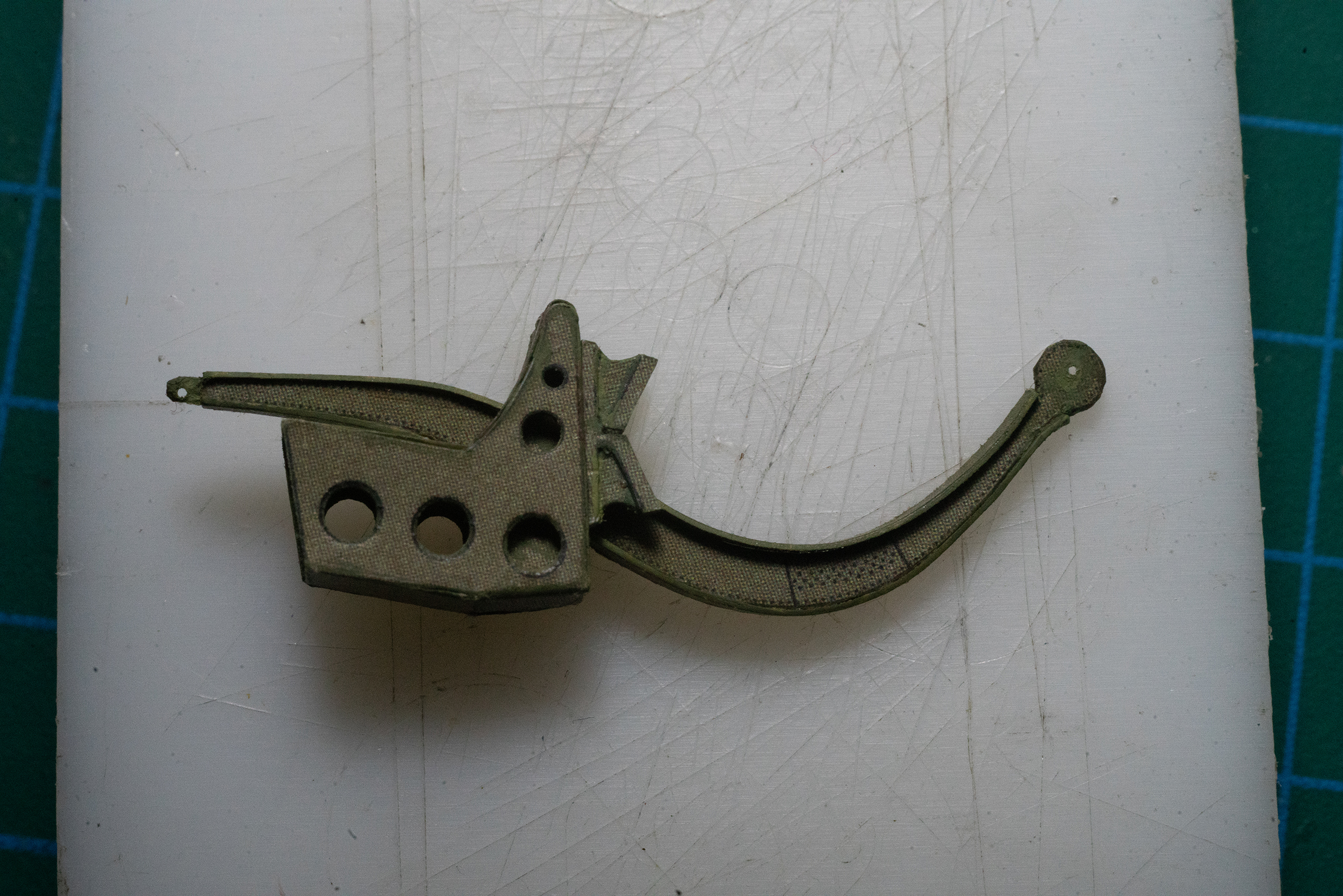
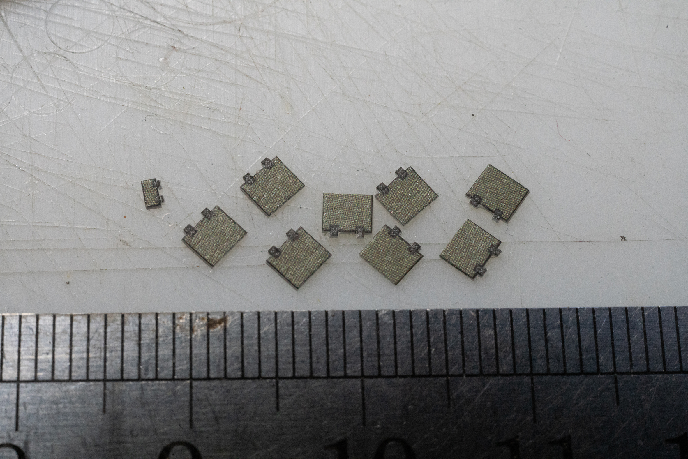
The construction of the davit block was fiddly, requiring more than two hands and ten (fat) fingers, so I need time to work out a better way to do the other three with more precision and less luck. In the meantime I managed to steal a few minutes to cut out the hatches for the hull, which required some accuracy:

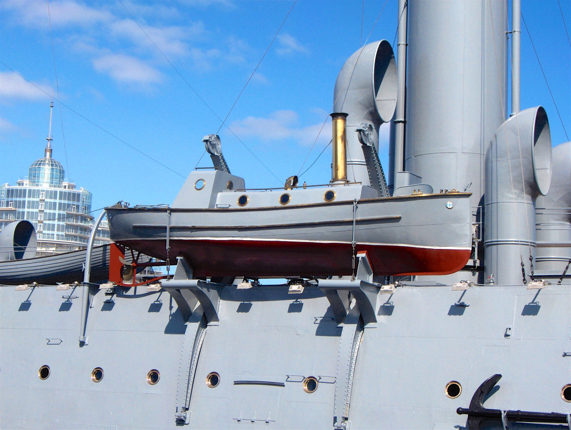
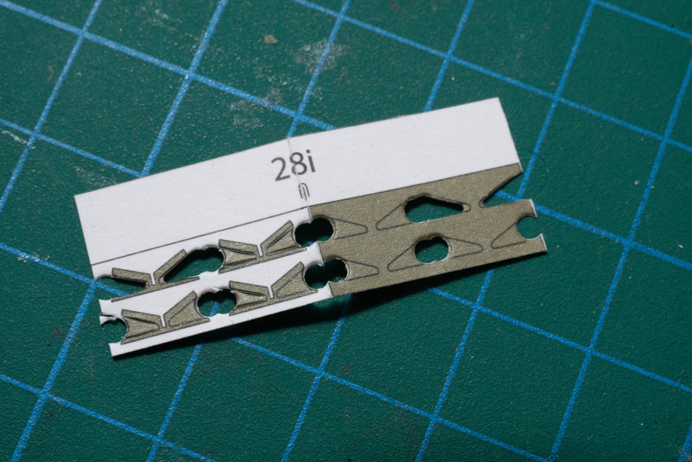
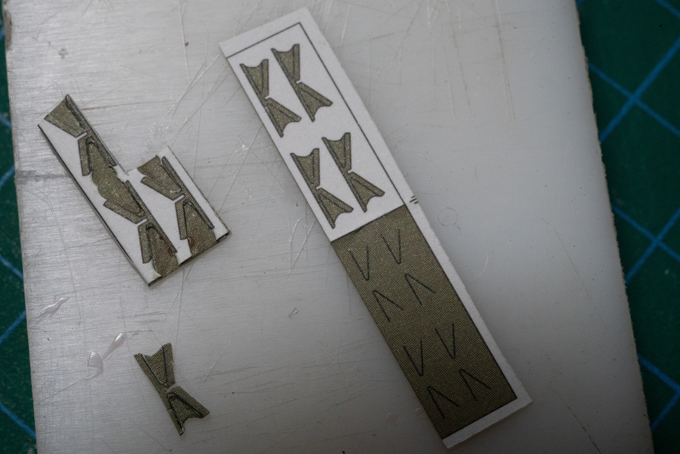
To complete the topside of the davit block, I decided to have a go at the blocks that the launch sits on. As proposed in the kit, these are flat-sided and so not very true to life, so I decided to make them  three-dimensional as they should be, to improve their appearance in the rather prominent position that they sit in!

This is what they should look like:

They were primed for folding as originally planned and carefully lined up on both sides. In between I placed a third sheet (made of two printed layers back-to-back after thinning them down by wetting, rolling and stripping the printed side from the white back). You will see that the sheet is both cut and punched to give the right shape, here only part-finished.

Look at the difference between what was originally intended and my extra effort:

After that the pair I made were mounted on the davit-block:

At this stage, after trying it out for size on the ship, I discovered that the curve of davits themselves was a bit flat, meaning that the launch wouldn’t be able to sit on the blocks at all, so that has been corrected and the others have been corrected to suit. The davit-heads still have to be addressed as well as other details before the davits are fitted properly later.

Like other protruding and/or fragile items that might become damaged while handling the ship during the build, these will be fitted near the end when I consider it safe to do so.

Some of these parts were included in the acid etch sheet, but would have been difficult if not impossible to incorporate, due to the construction. The whole sheet I find was filled with unnecessary parts and omitted many more that would have been far more useful – the wheels for the Lafetten, for example, that are missing altogether and would have been more appropriate. I shall use those left over from my Bogatyr 🙂

For the full report, please go to https://thingummybob.com/modelmaking/building-dom-bumagis-diana/

Diana Decking entirely of real wood planking…

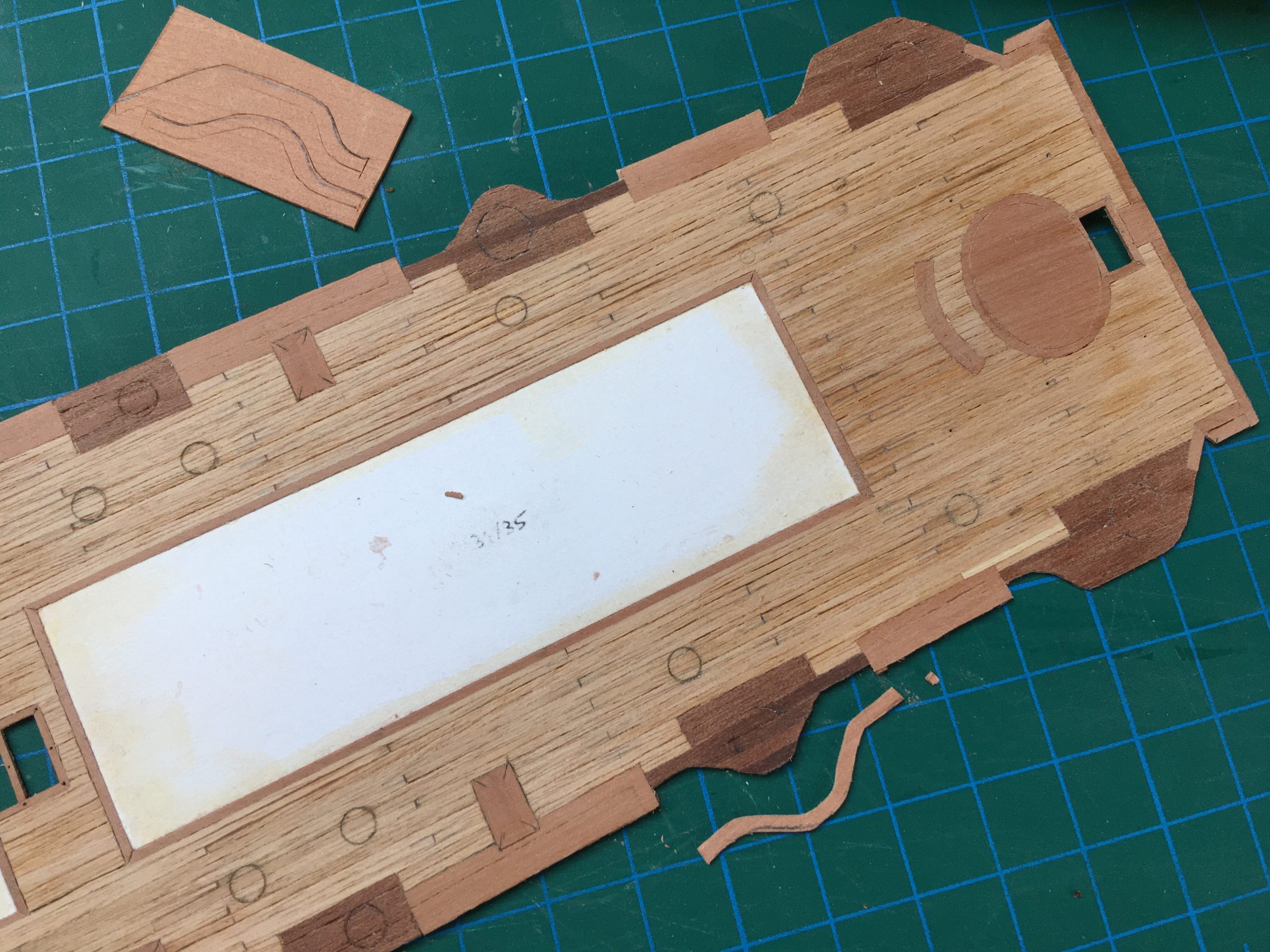
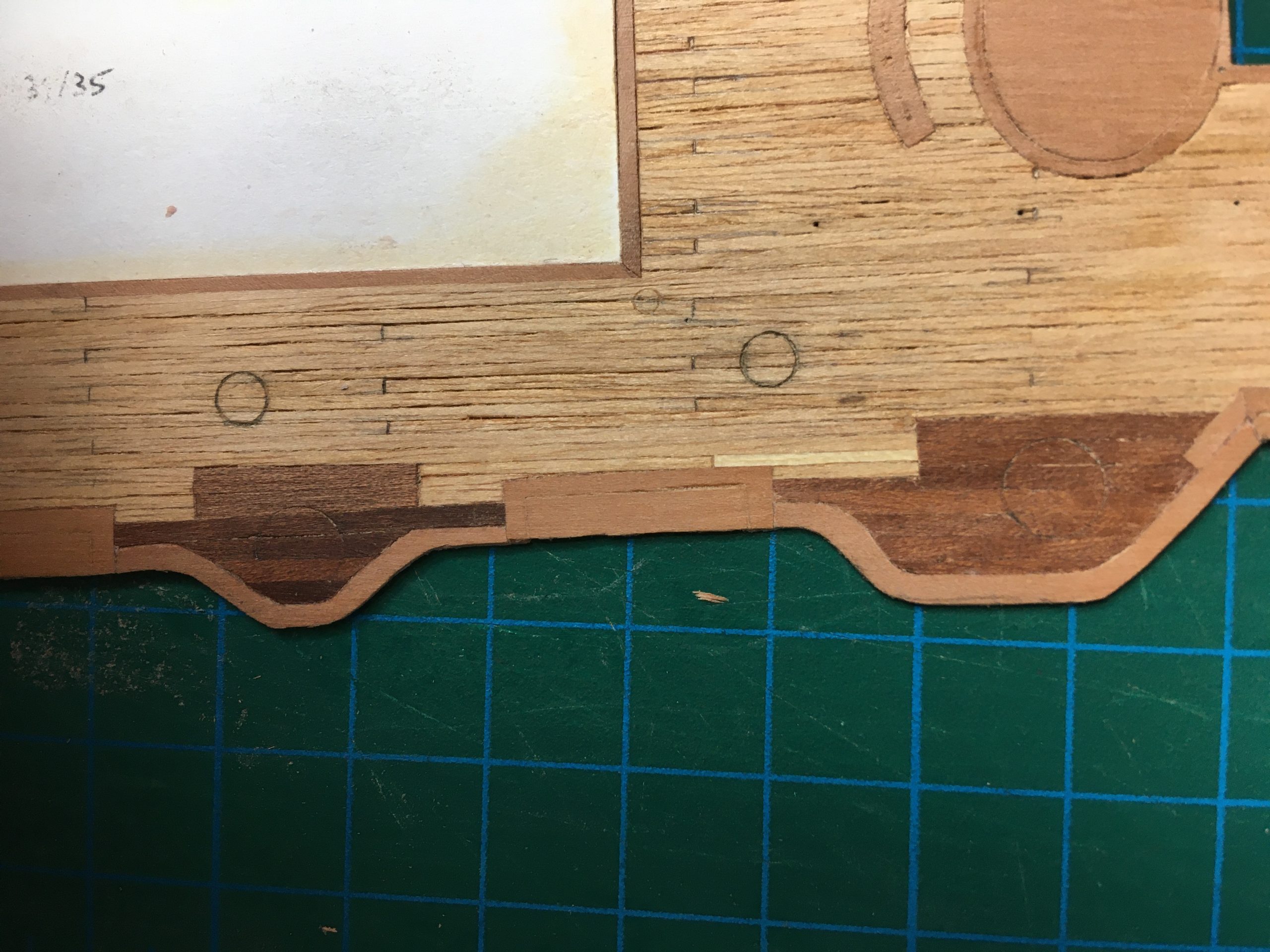
I made the decision again to do the deck in real wood, planked as the original, like some of the other ships I have done – to me it really is worth the trouble. I still had some very thin veneer of the right sort and set about cutting strips about 0.7mm wide in preparation for the bow-deck. Here the deck is started, a sharp scalpel and ruler for cutting and placing the planks. A razor was used to cut the strips, the scalpel is used to cut them to length as I glue them to the reference base – a scan of the original checked for size (VERY important, as scanners and printers do the strangest things to proportions!) and printed out on very thin typewriter-copy-paper.
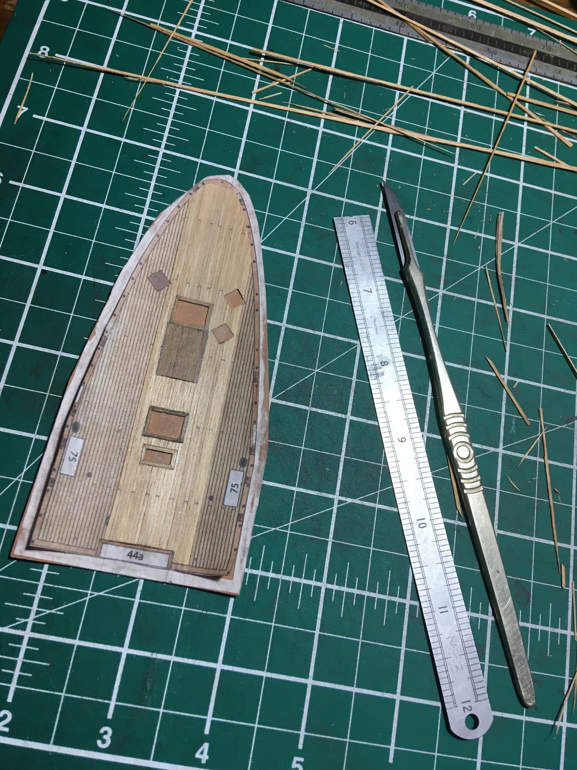
Cutting is a lengthy process and requires an extremely sharp and thin blade and a good straight-edge. As a straight-edge I prefer to use a scraper, as it is sharpened to cut on the edge. Very usefully, the mushroomed edge grips the paper or wood under it, which is ideal to stop creep while you are cutting. If you don’t have one or know how to sharpen it, any carpenter or furniture-maker will lend a hand, I’m sure. Any metal ruler will do, of course, too.

As a blade, use a safety-razor-blade, an old cut-throat razor (my favourite), a scalpel or a ‘Stanley’-knife, whichever is more comfortable. I actually use all of those, depending on the job, though for the decks, both the razors are more accurate for the strips, cutting a proper 90 degrees as the blade is so thin and doesn’t ‘cut and wedge’ like the thicker scalpel and Stanley tend to do, leaving the cut edges in a ‘v’ shape. Any tendency to wedge can be nasty when combined with a slightly angled grain, too, pulling the knife along it. A thin blade is paramount when ‘correcting’ the width of the planks, since realy minute amounts are shaved off to get them ‘just right’. What you cannot see, is that I actually sand the edges of some of the planks to get them at right angles and to be the right width 🙂
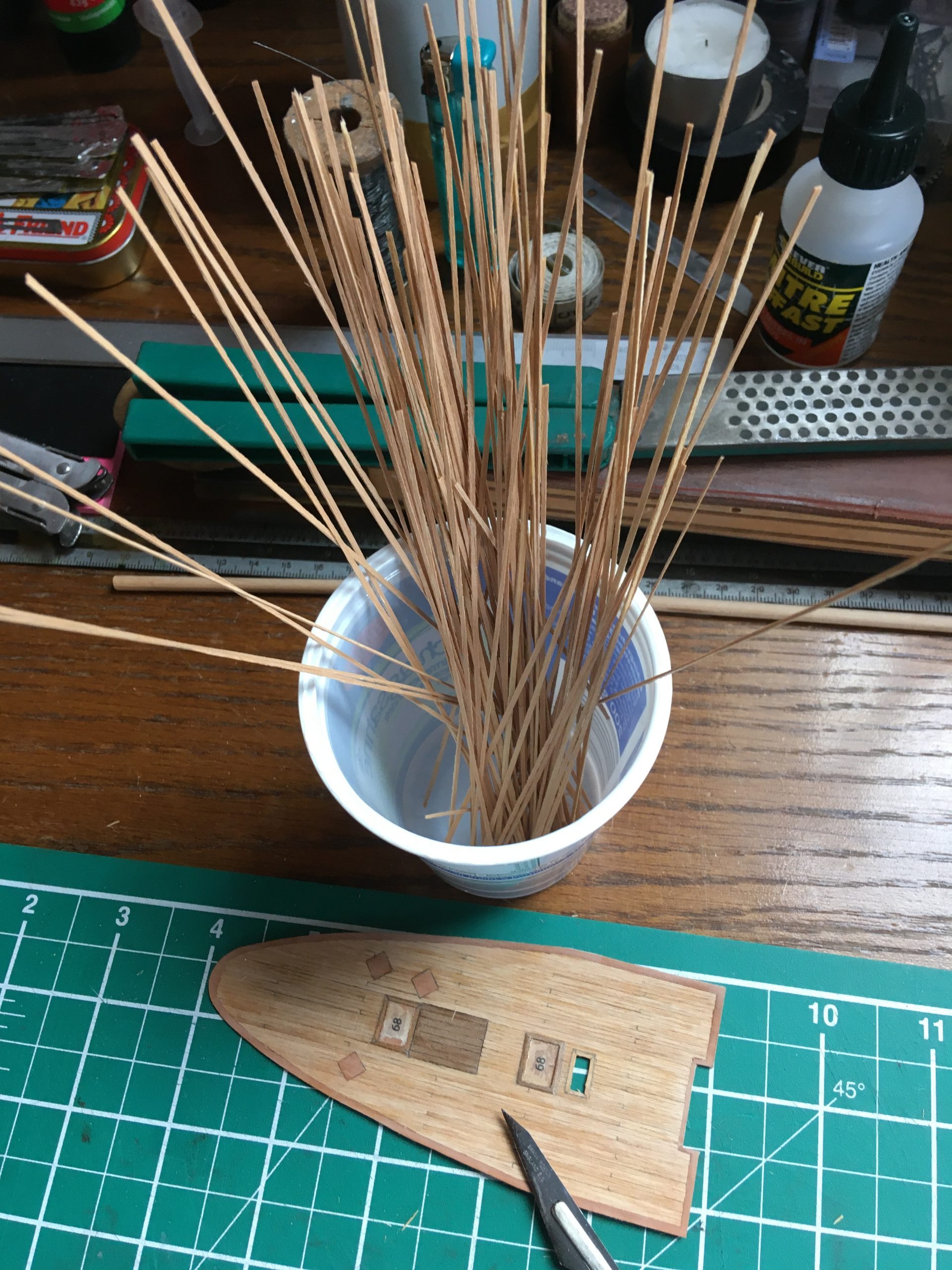
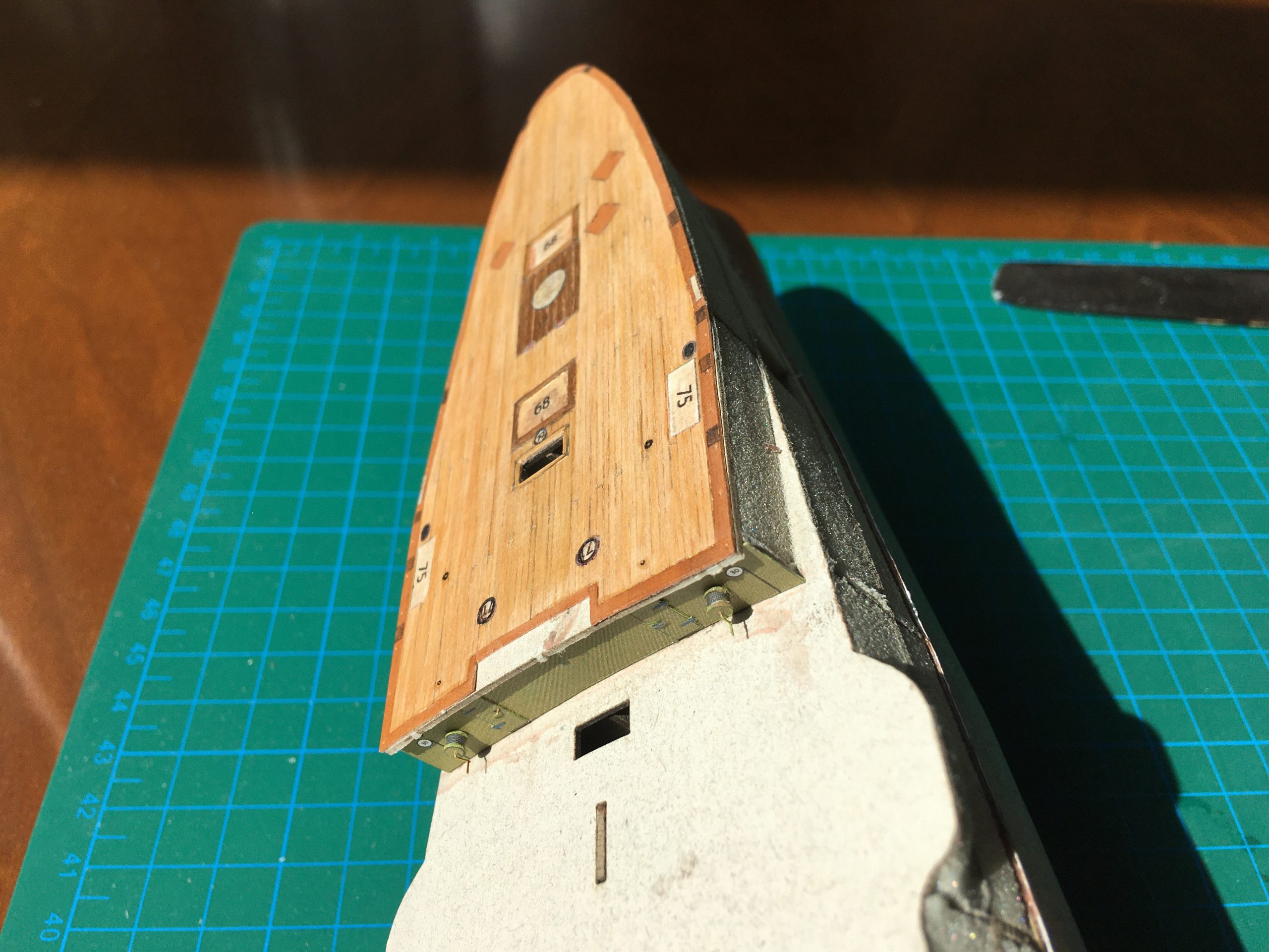
The forward deck is planked and there are some more planks ready for the aft portion of the deck, which comes next. Here are a few pics at the beginning of the planking process and the started work.
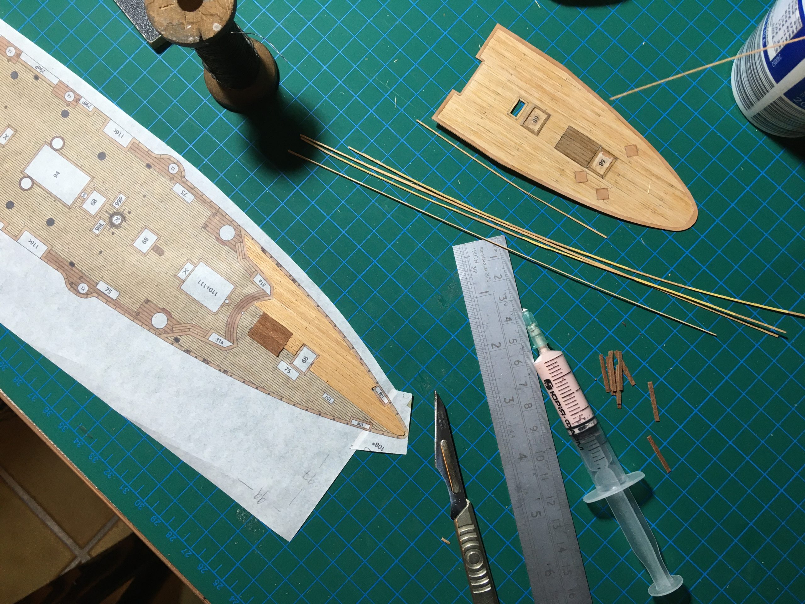
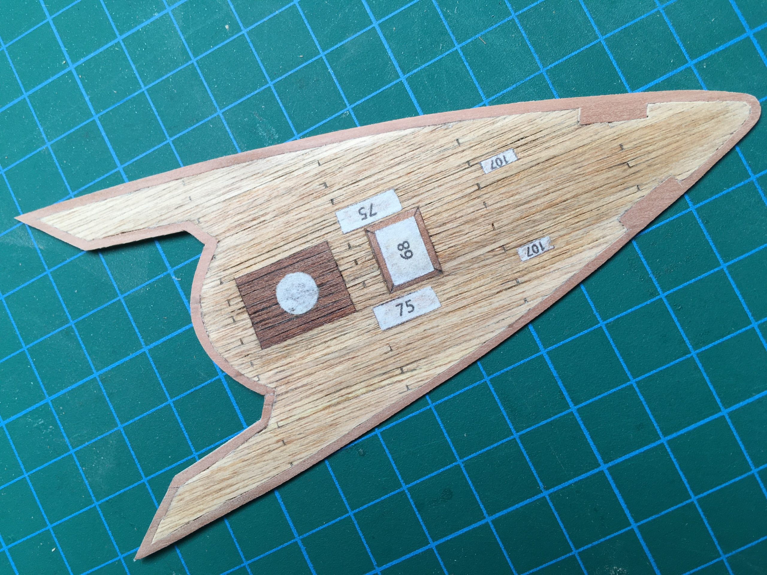
Here we see the finished aft deck planked in various woods placed over the original printed sheet from the model. A nice weathered look achieved with Schellack and elbow-grease. Hopefully not over the top when it’s finished. The individual planks are never cut from the same strip when they are laid, I always mix them up, otherwise I could take any piece of veneer and draw the plank lines on it. My rather more complicated method gives a little more of an ‘authentic’ look and feel to it, I hope.
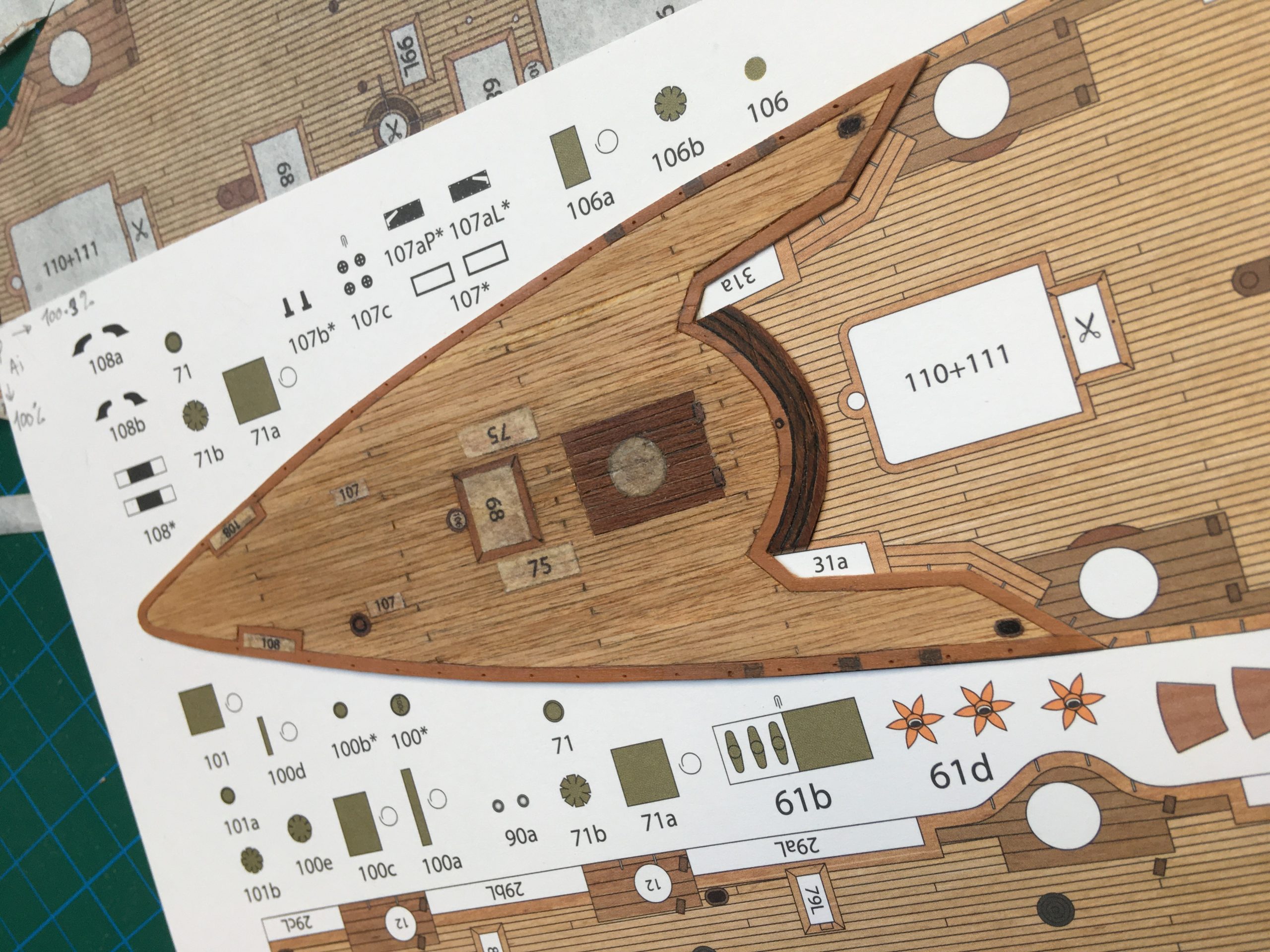
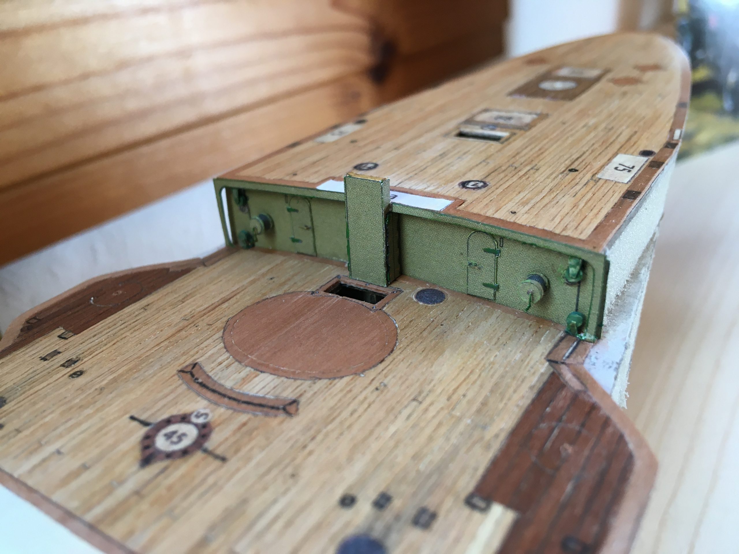
And here the fore-deck in the same manner.
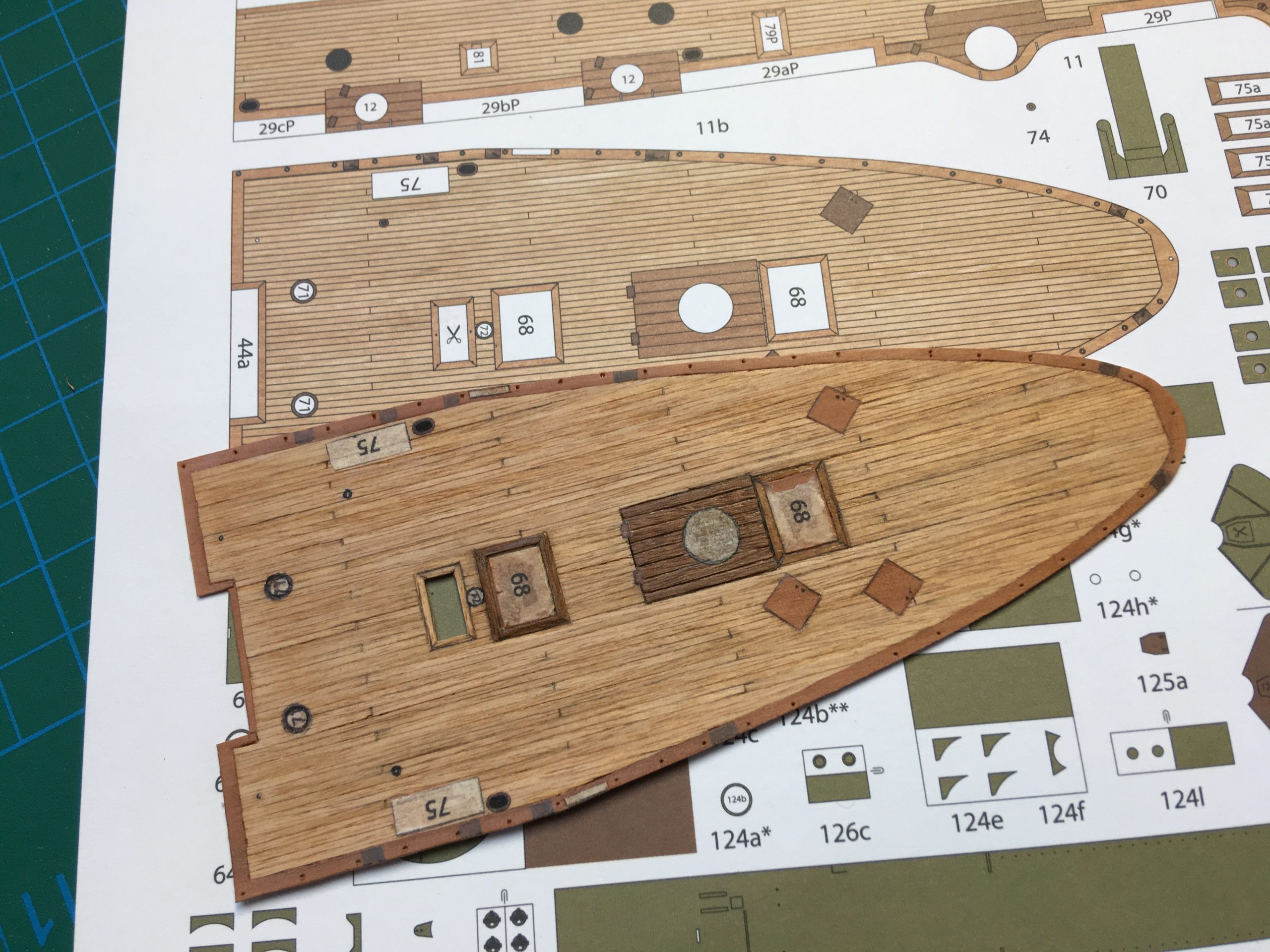
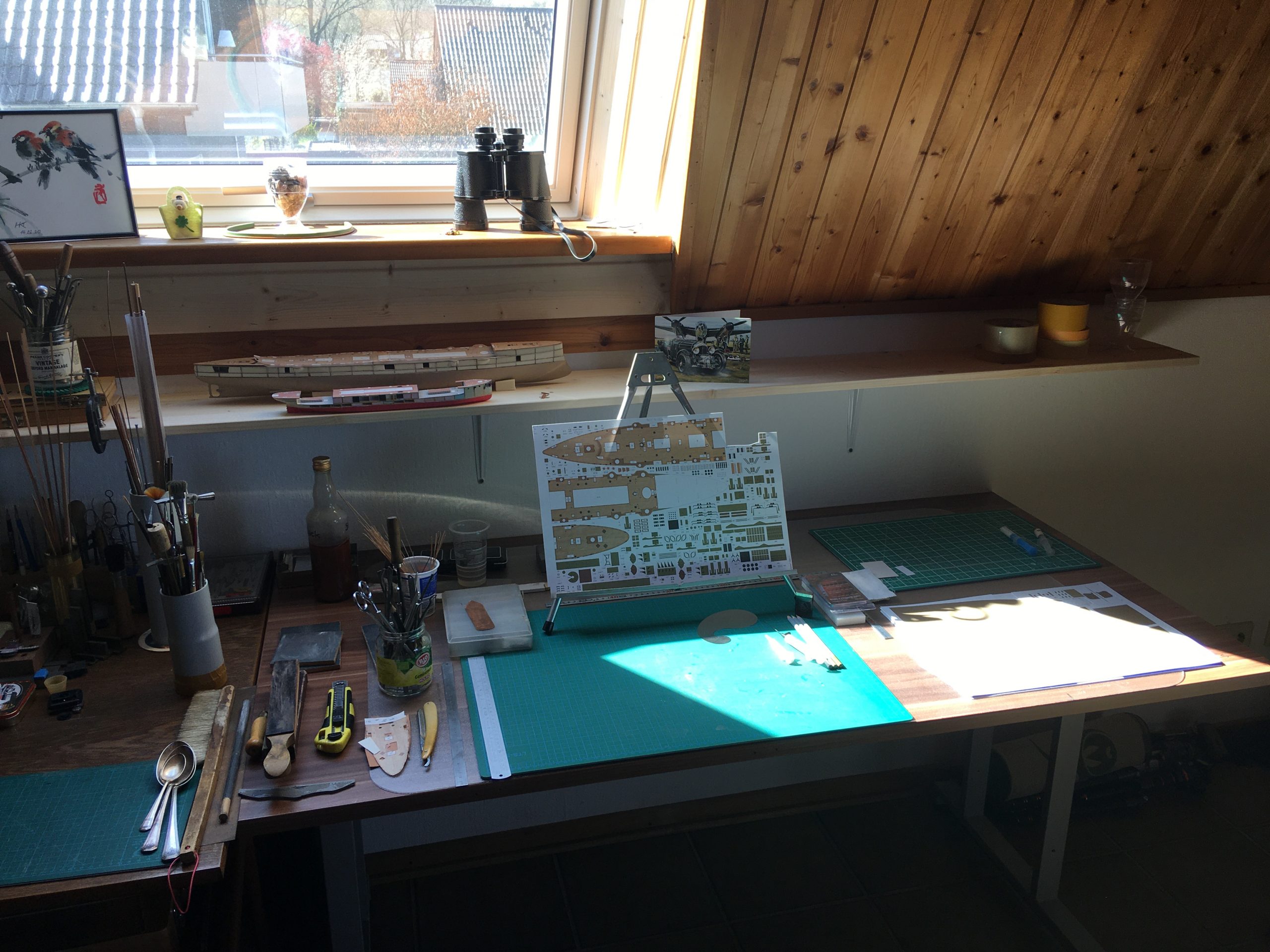
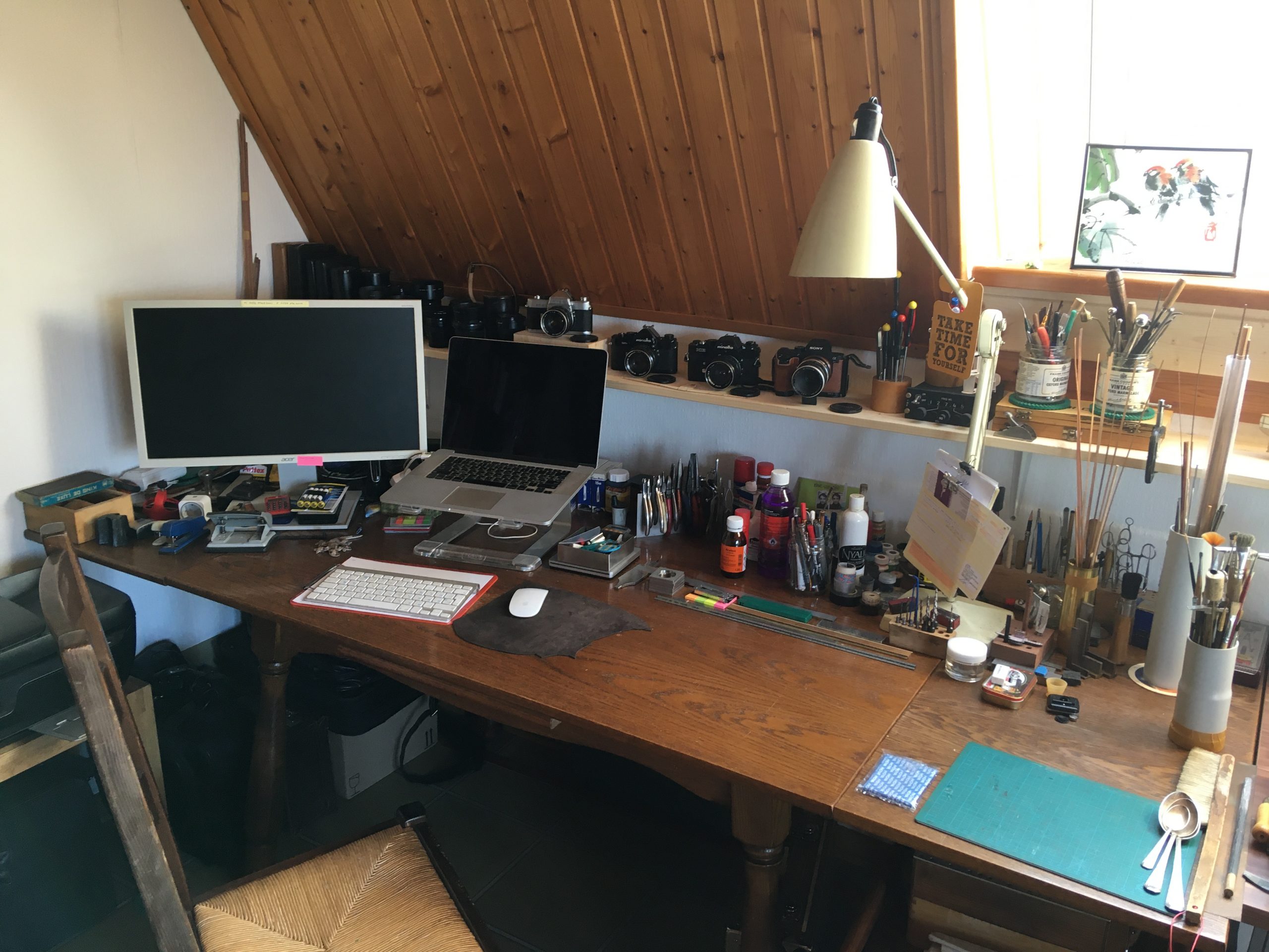
You may even spot the array of tools and useful bits and pieces in the background now and then. Here is a view of my workspace in the ‘living-room’, where Maryna does her art (mostly painting) and I do my various tinkering. Looks nice and tidy here, doesn’t it!
While the deck was drying, in between I finished most of the hull below the waterline, as shown earlier. Before I can even think of attaching the hull-section above the waterline, the below-decks 75mm Canet guns have to be made and installed in the hull and the deck has to be completely finished.

The finished deck now looks fine glued in place:
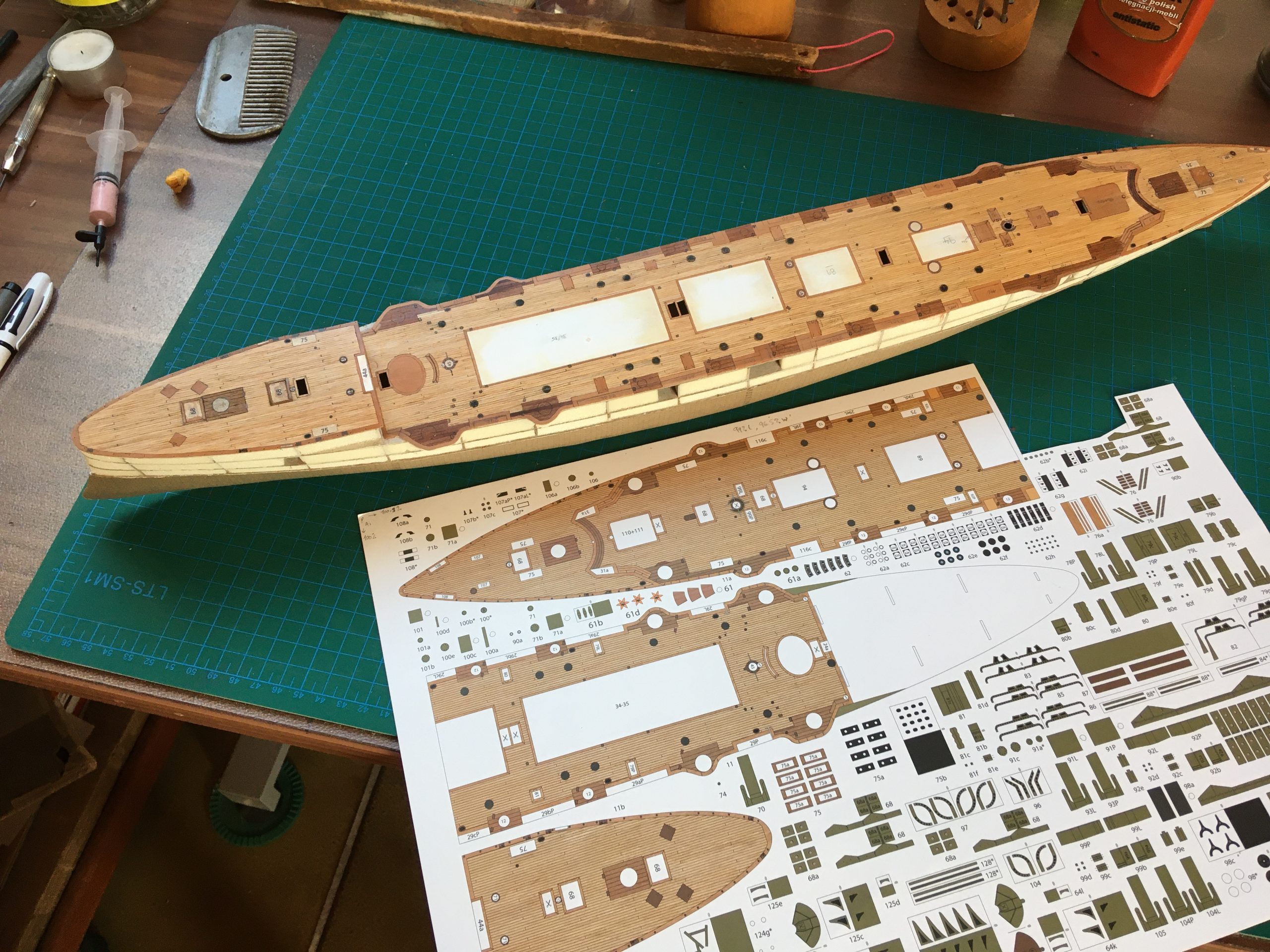
Some close -ups showing the laid up decking:
The foredeck fitted + the entrance to the deck below – just trying for size before fitting the main deck.
For the full report, please go to https://thingummybob.com/modelmaking/building-dom-bumagis-diana/
Removing the top of an SR- camera safely

The whole SR series of cameras from Minolta are similar in their construction. The only departure from the theme would be the SR-7, which has an in-built light meter and battery, but the basic principle is actually valid for almost any mechanical SLR (with notable exceptions, of course, like cameras with removable finders).

I have prepared a short video to show how it can be easily and safely done without doing any damage to camera or yourself. What you do afterwards I can take no responsibility for. I only need to access inside the top to clean the prism faces and check the cleanliness of the film-winding mechanics. In the case of a stuck camera, 99% can be done just by removing the BASE plate and adjustment or cleaning of the slow-gears are inside the mirror-box, as previously described.

Here is a link to the video, while I try to resolve the uploading problem that I now seem to have…

https://www.dropbox.com/s/wezkvi41sao6h2z/Video%2006-12-2019%2C%2014%2043%2017%20Copy.mp4?dl=0

The video will soon be uploaded, but first I have to do a light edit to remove my head from blocking the view… 🙂

Interesting for those that have never looked inside one of these, there are internal differences even between early and later versions of the SR-2, as demonstrated here!

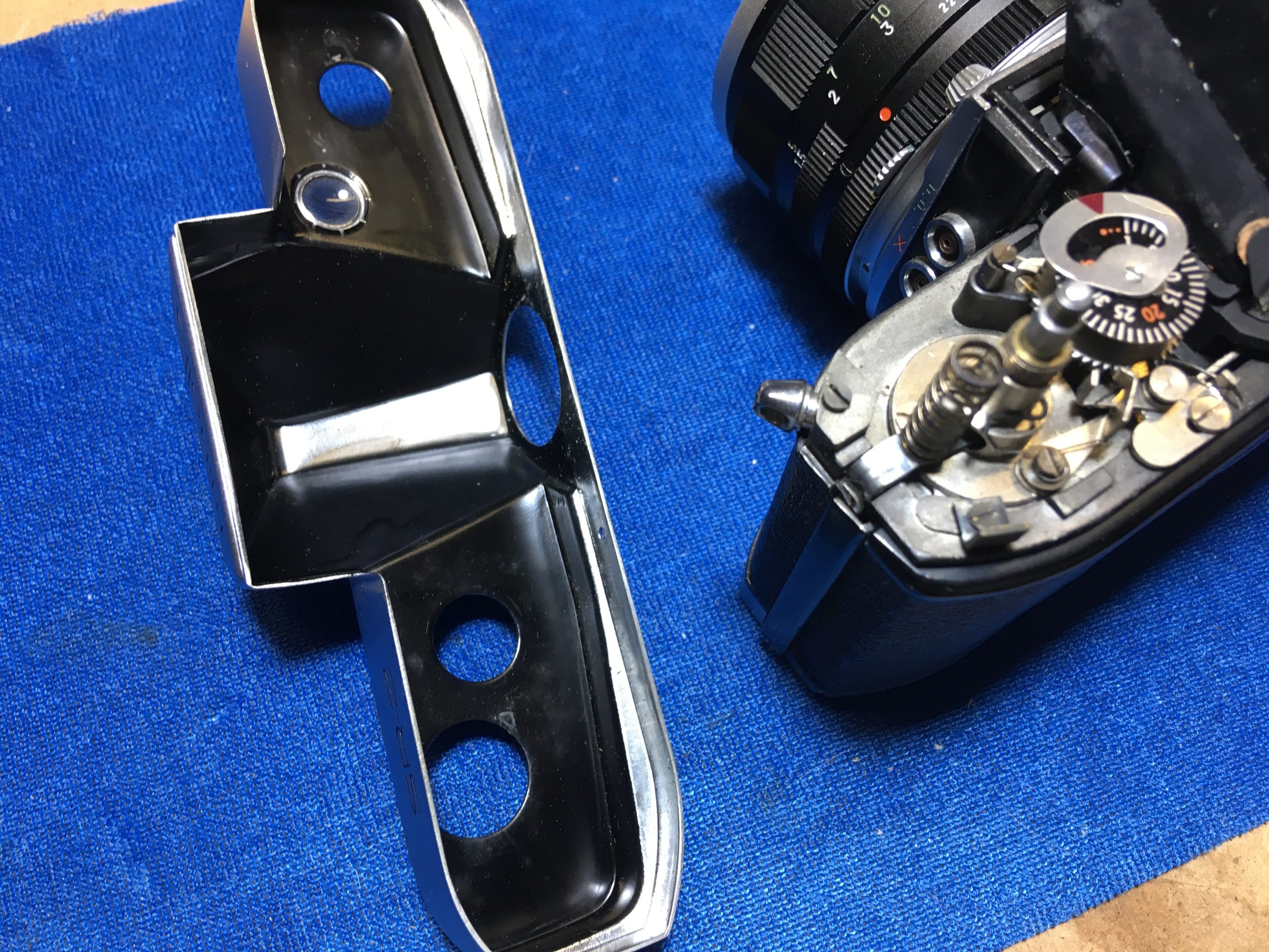
This is an early model (1100783) and just look at this! The inside of the top pressing has been hand painted in black on the inside

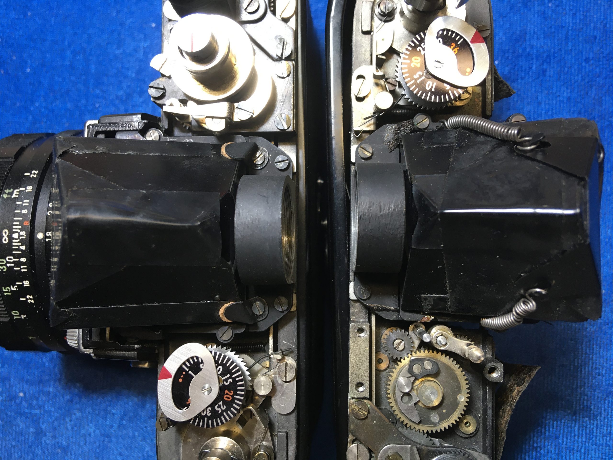
Before wiping off, there is a little mould on the prism (corners masked off with black insulating tape) and the holding mechanism for the prism is very different to the ‘later’ models (as of when?) Clamped at the back and sides instead of the customary overslung bracket and springs, over a plastic moulding protecting the prism. (See below, both are SR-2s – the one on the right has the film transport partially dismantled)

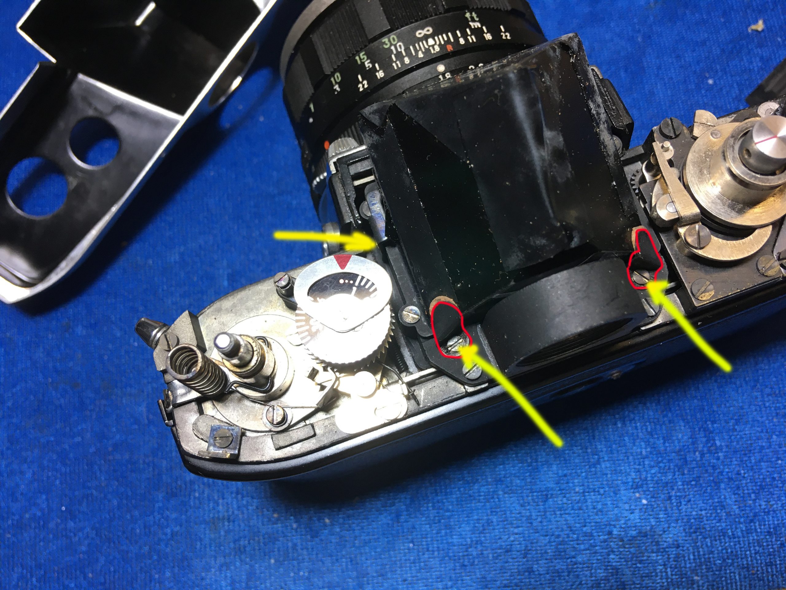
The yellow arrows show the screws on the brackets to remove them, the red outlines the brackets somewhat…

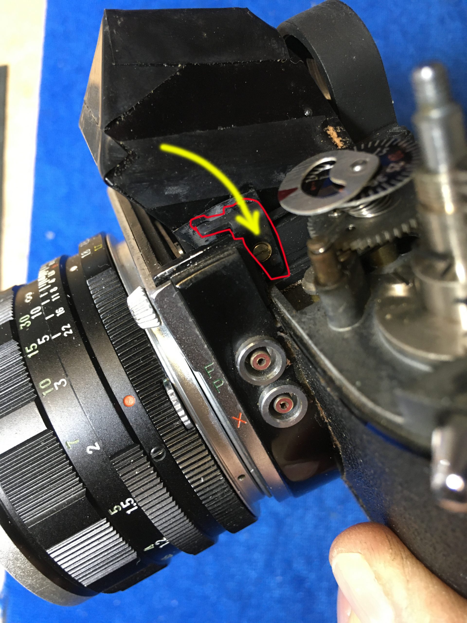
This is the one that is accessible on the left – the one on the other side is not! This one only needs to be loosened.

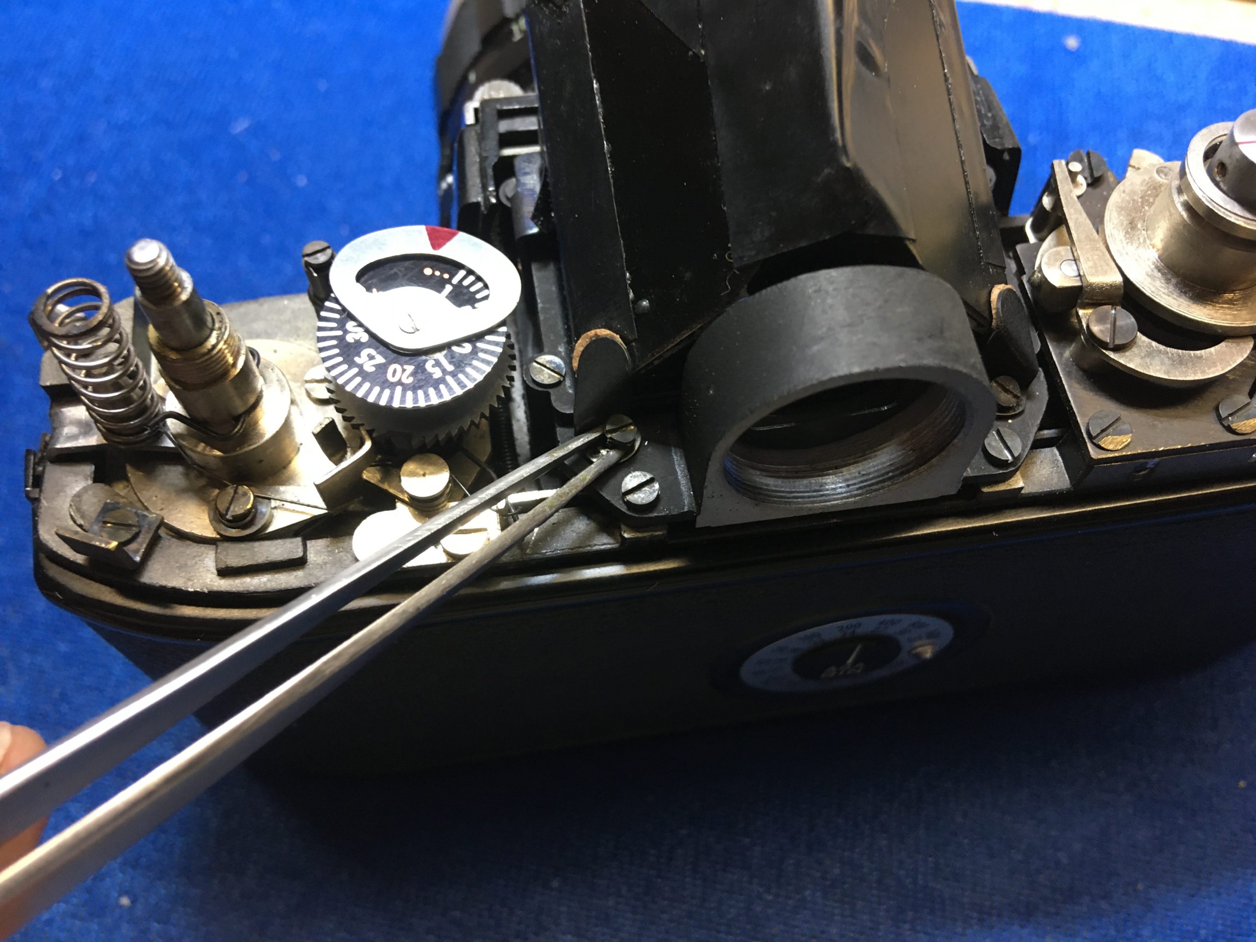
Once having removed the screws and brackets, the prism has to be lifted about ⅛” or 3mm upwards to release it. Here is mine and, though not really very visible here, the specs that you can see are  fungus ‘spiders’ settled and spreading on the prism… easily removed with a 3%-10% peroxide solution applied with a soft artists’ paintbrush and a quick wipe-off – no costly coatings to worry about here, anyway! 🙂