Masspacher finals :)

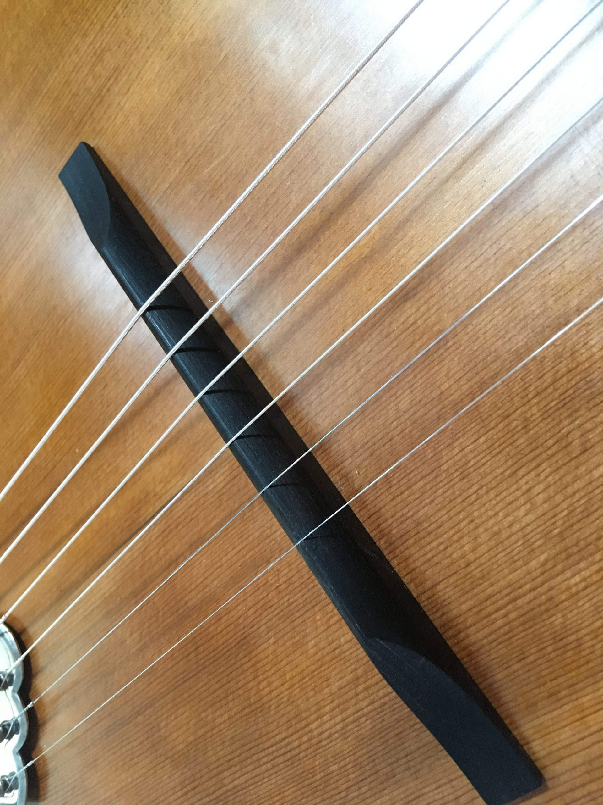
Now at last I am approaching the time to assemble everything and try out the bridge that I made (of ebony, of course!), string it up and try it out for the first time…

The new machine heads – without screws (still waiting for the correct domed slotted ones instead of the modern cross-head-screws)

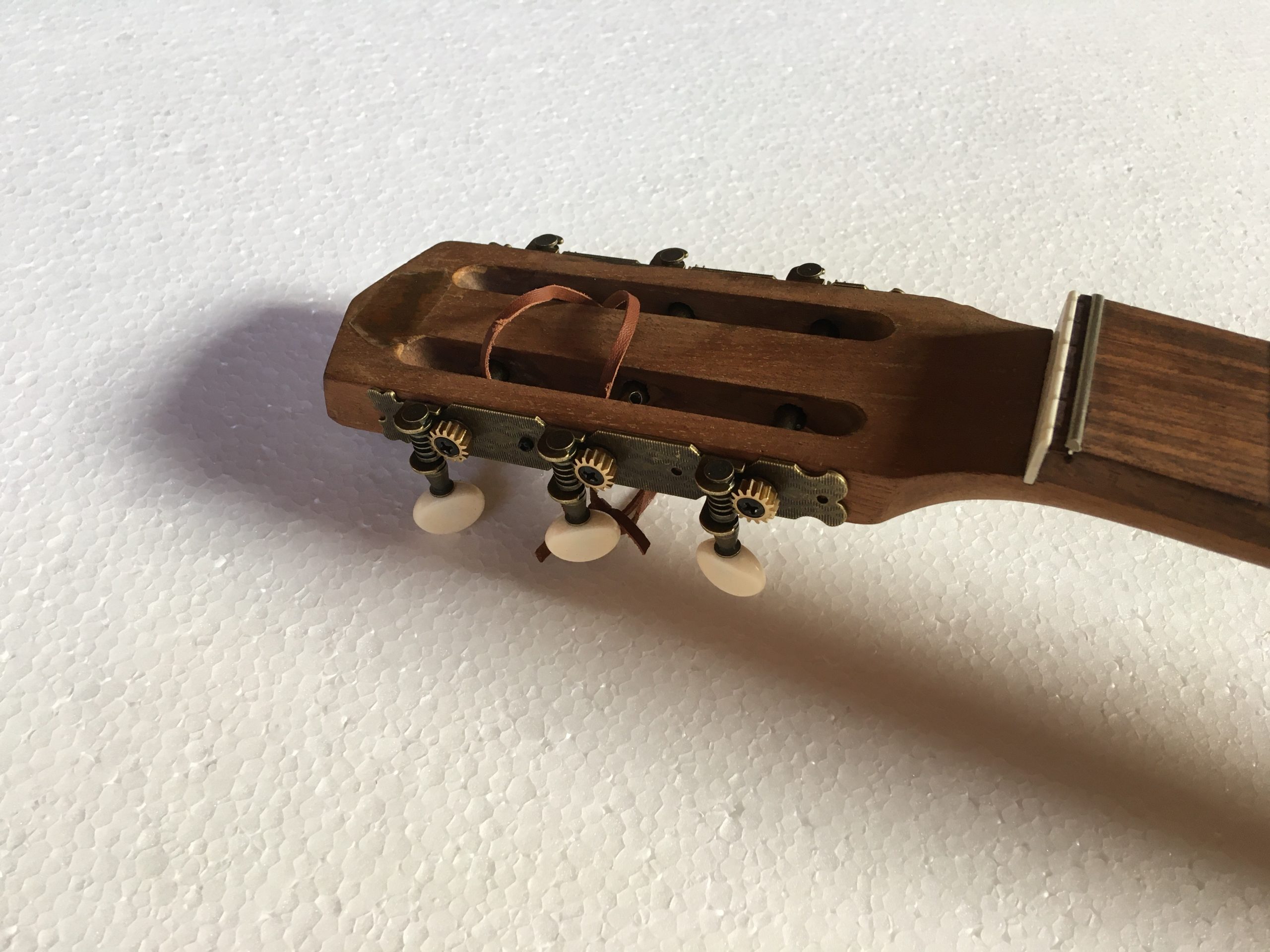
Nice and simple inlay work on the ‘rosette’

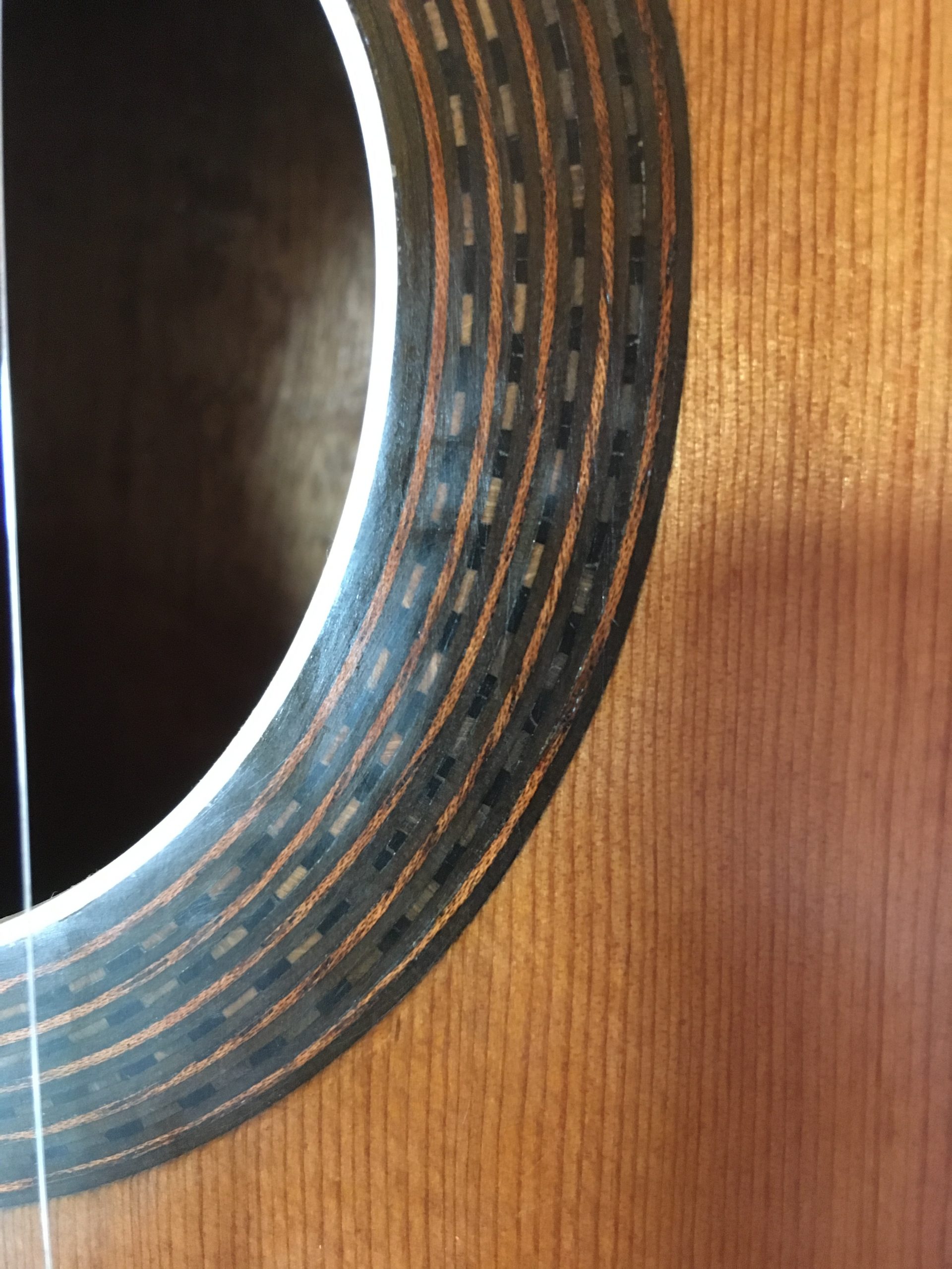
Ready for the bindings/purfling and the frets and nut already fitted – notice the subtle difference in the colour of the top where the original bridge would have sat for years, shielding the wood from darkening (more obvious in the photos below this one).

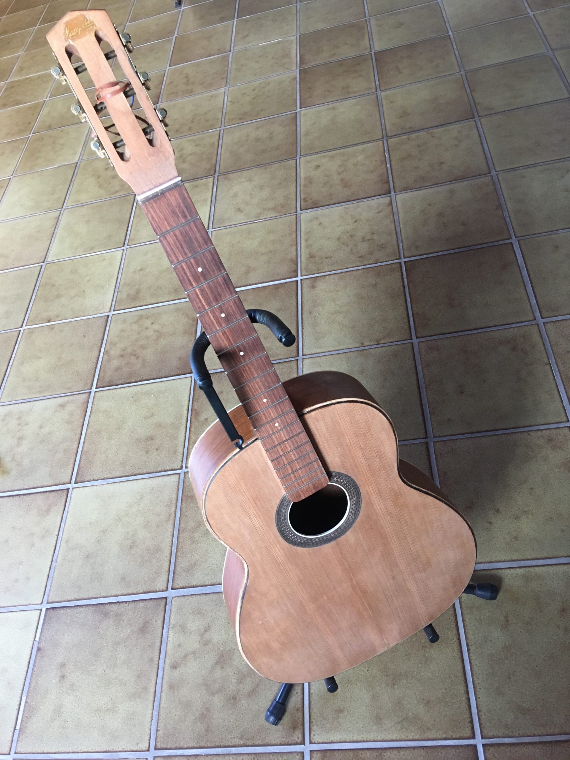
Here with one side taped to glue the bindings.

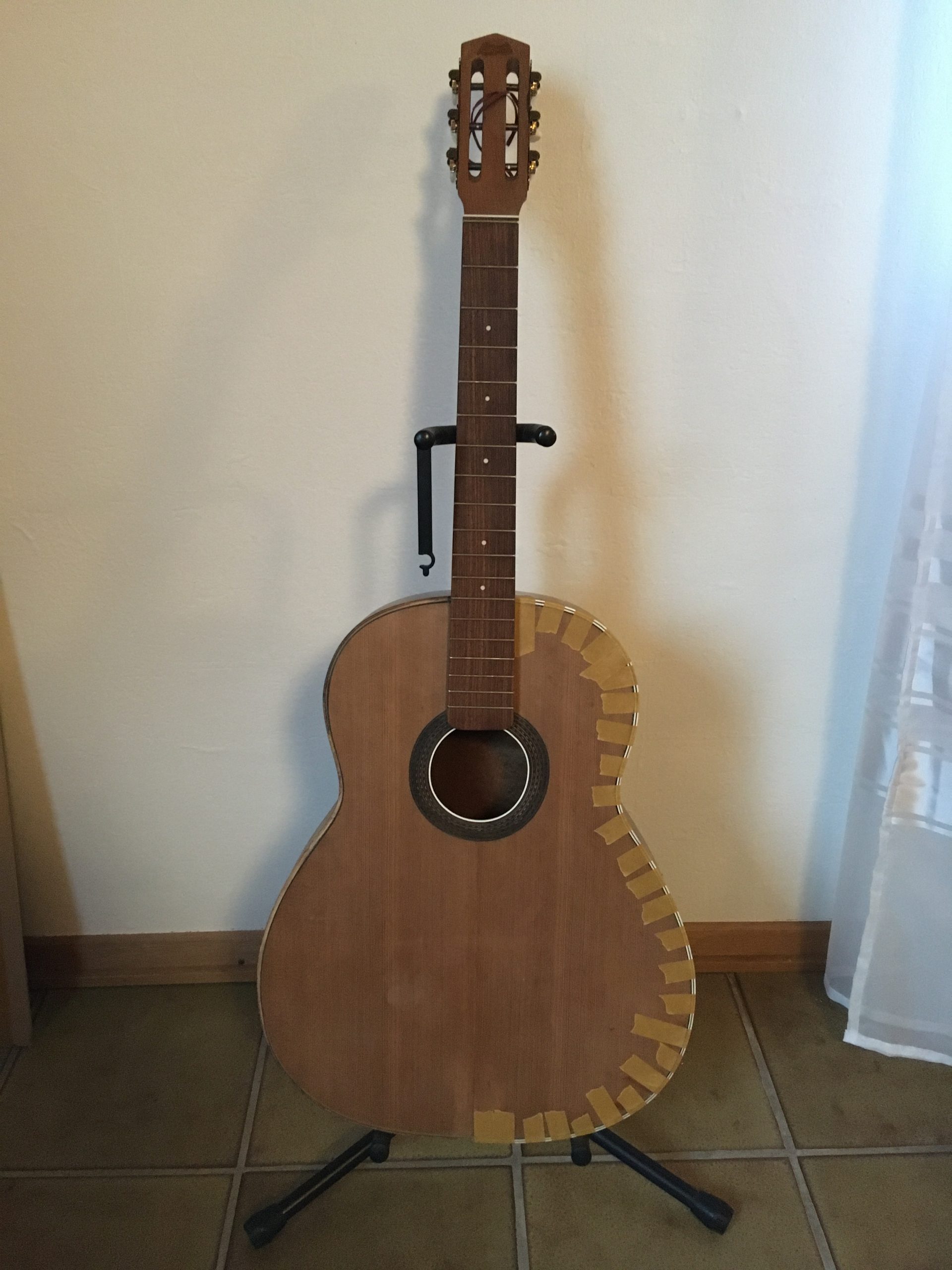
The second side being glued…

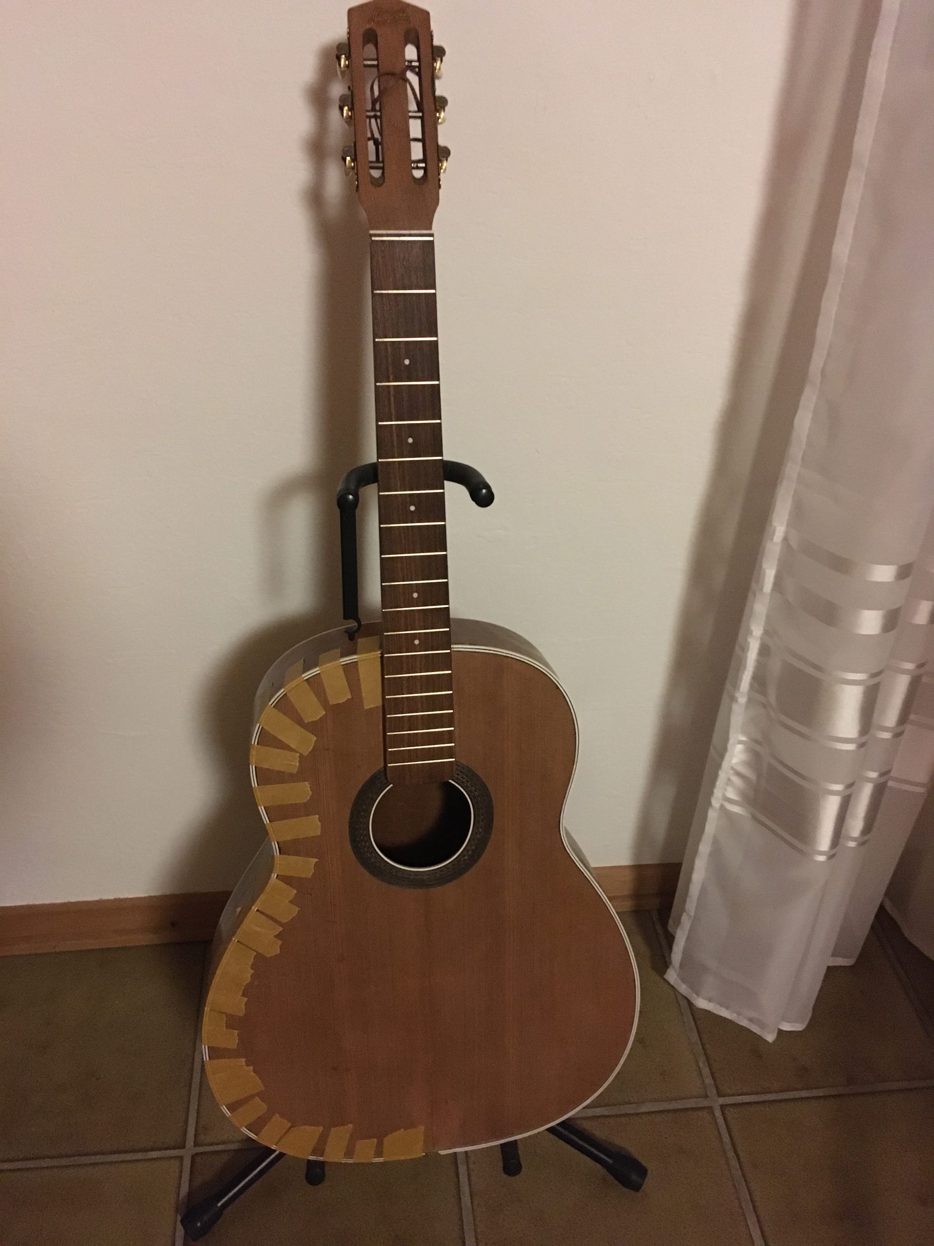
After fitting the bindings, all could be finally assembled… Here is the binding at the bottom showing the corrective build-up of veneer around the bottom end of the top. I can’t claim that it is invisible, but at ‘player’s distance’ hardly noticeable. It retains the the original top without replacement, retaining the idea of using as much of the original as possible. Putting a new top on would have defeated the object and to my mind, ruined the guitar.

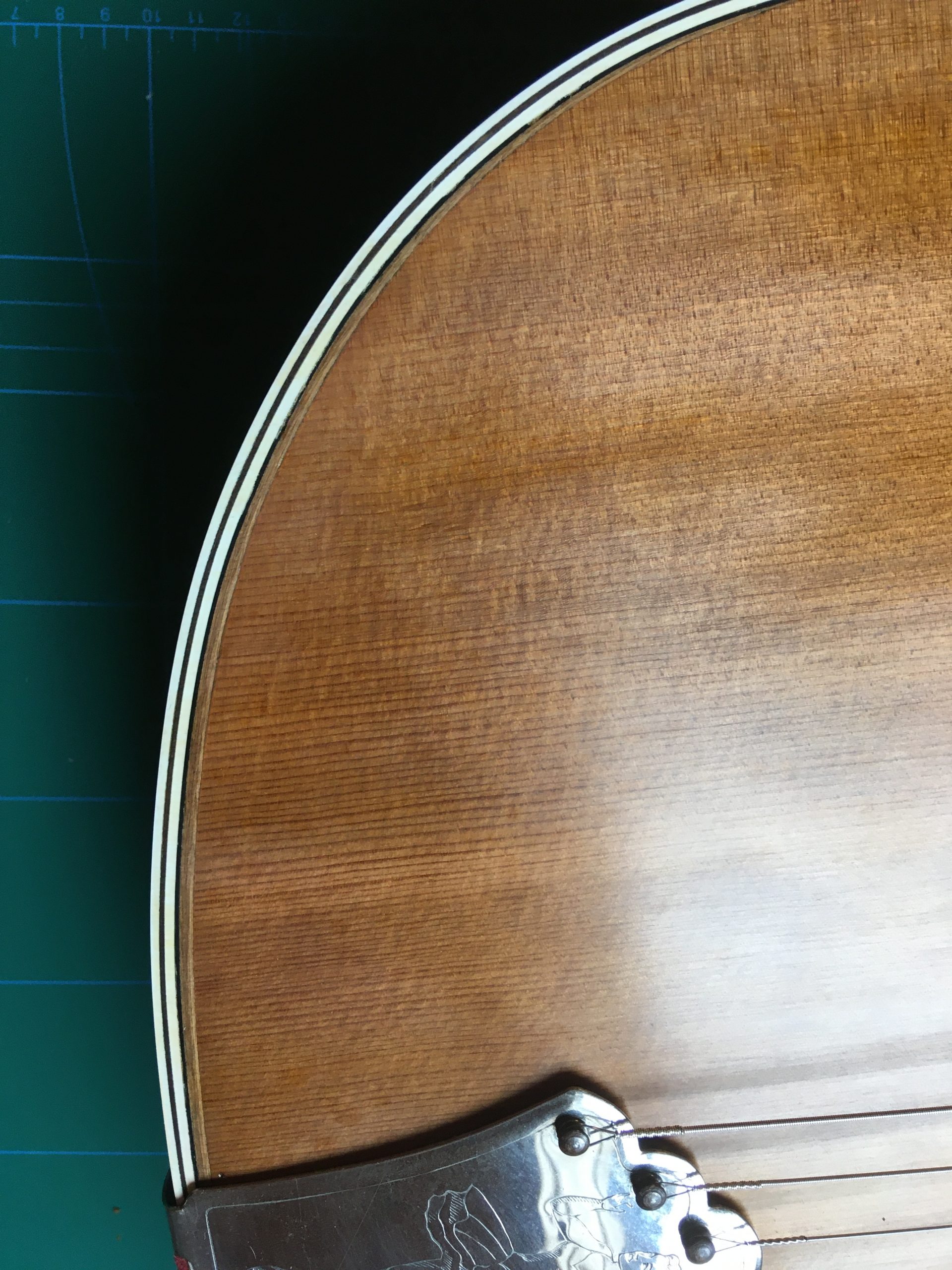
The finished article after shellacking and rubbing the front with 0000 wire wool and applying furniture wax. It will still need a little work and a few more applications of wax before it gets a proper sheen, but hey, this is a 100-year-old guitar and doesn’t have to look like it just rolled out of the factory!  
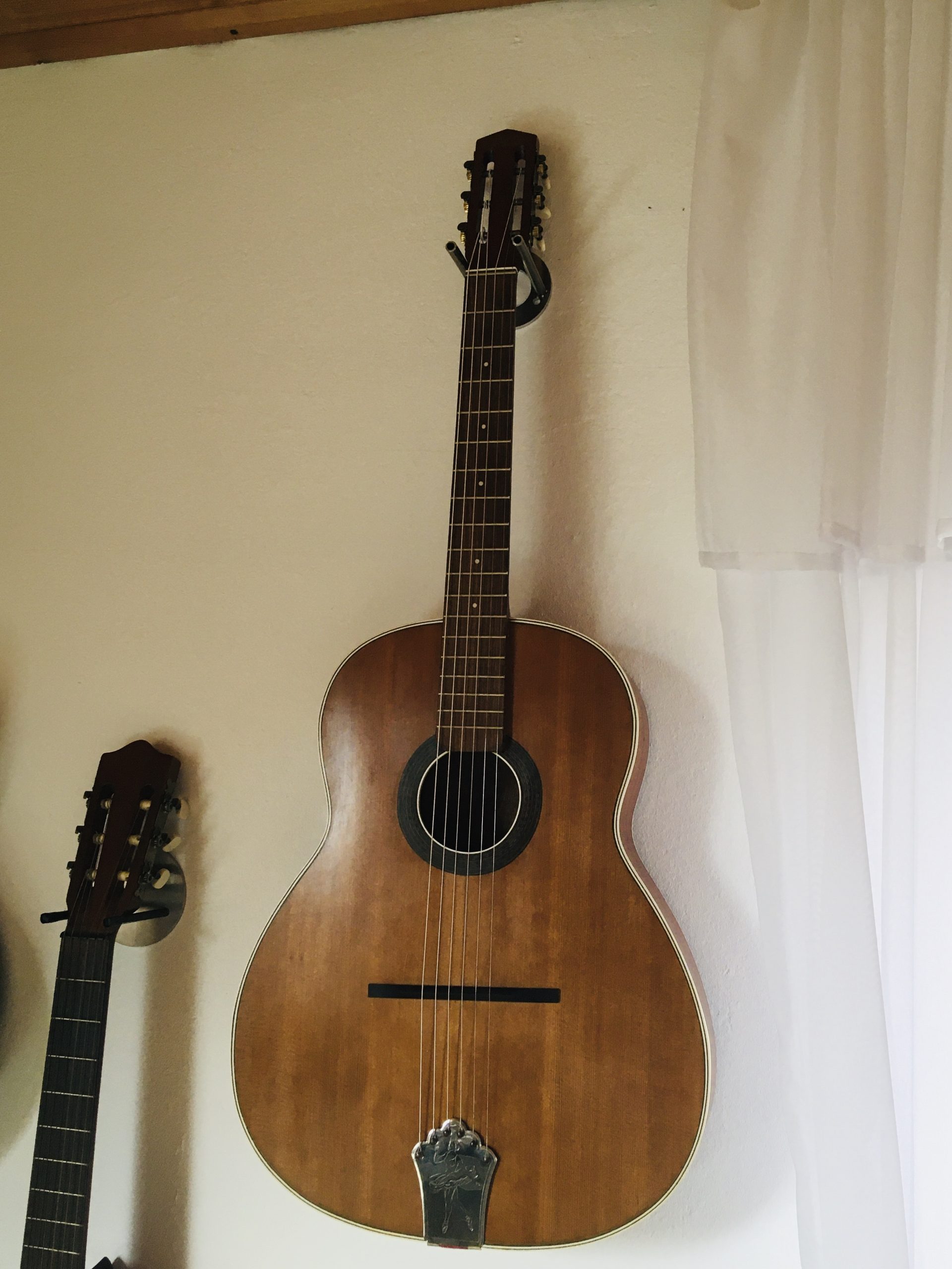
The back and sides were shellacked and de-nibbed with wire-wool and left in the gloss that remained

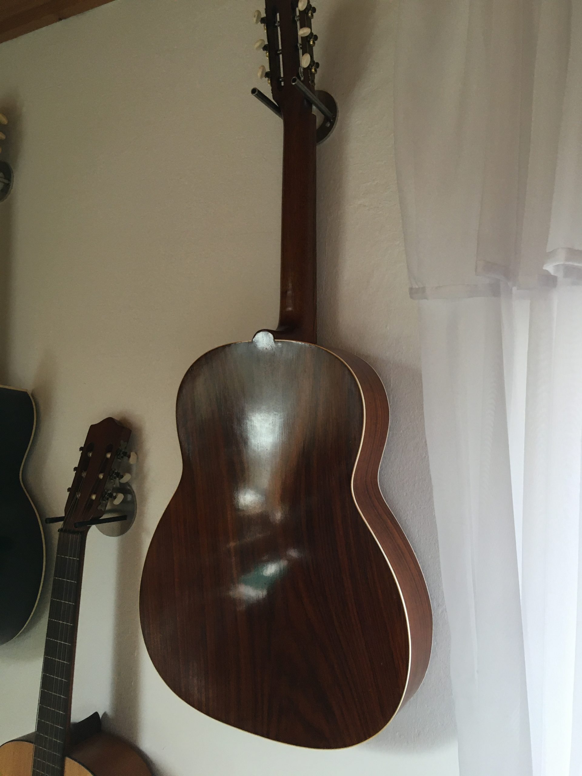
Its place on the wall at home (camera-distorted angle to the bridge, by the way!) next to an old Ukrainian ‘Trembita’ (Epiphone copy?) and a ’70s Höfner bottom-of-the-range (¾?) classical. The bass also (now) works active and passive, but was an electronic mess when I got it 🙂

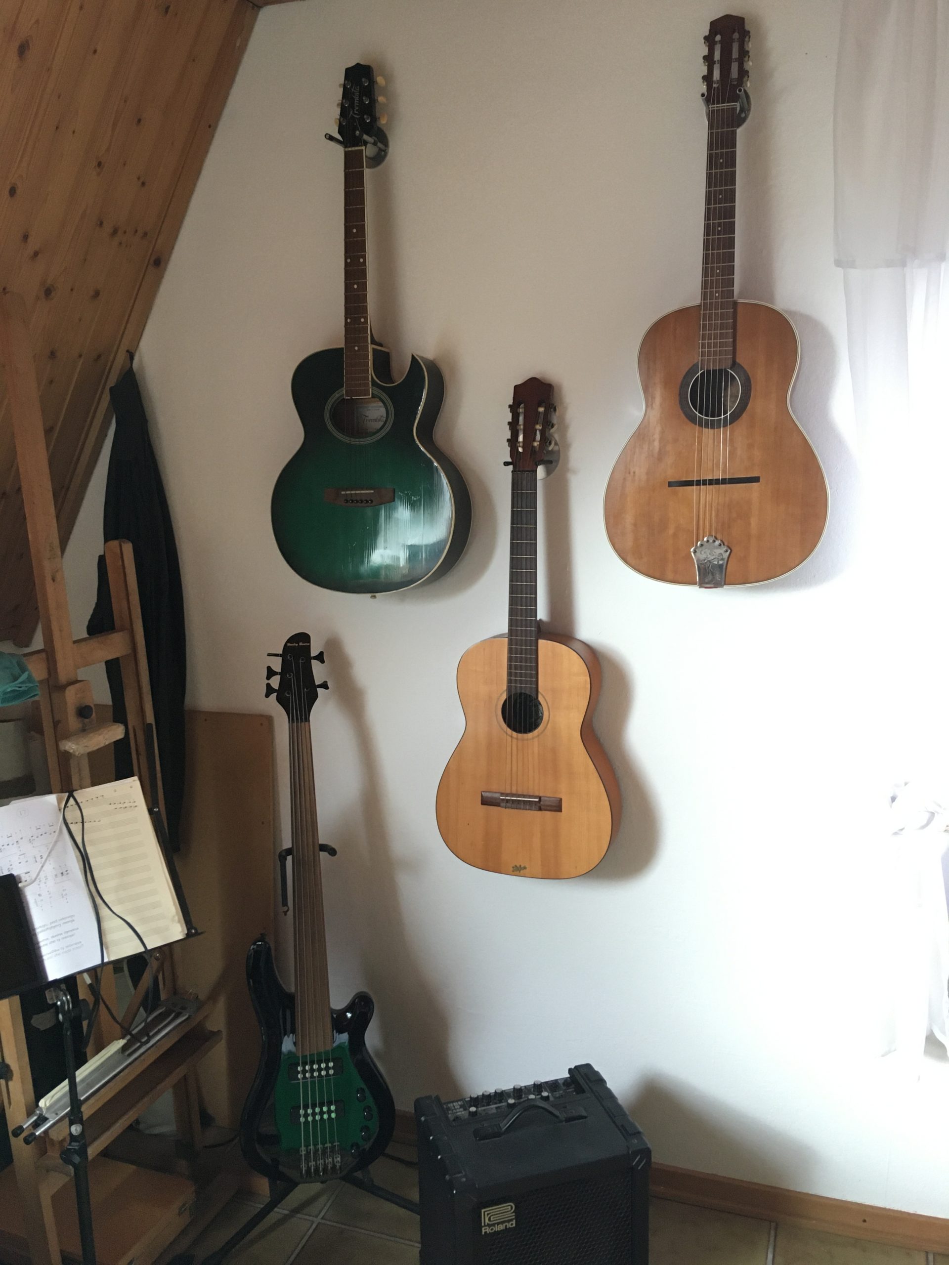
A new day dawns on the Masspacher which played very nicely from the word ‘Go!’. I may have to adjust it a bit as time goes by and it settles, but despite the gargantuan thickness of the neck, it plays with a light touch and strong tone – the sustain is great, of course!
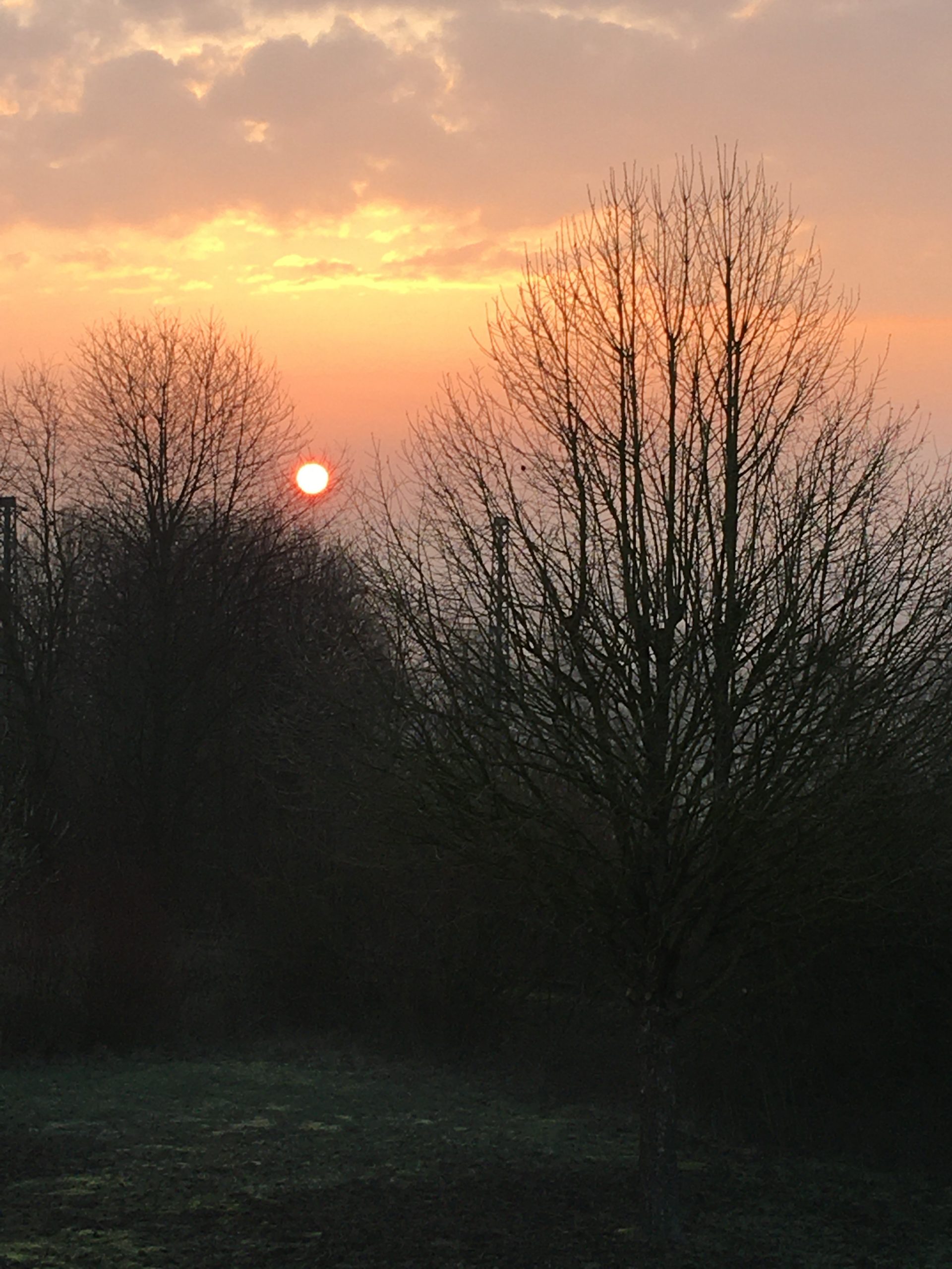
Maybe at a later date I will even post a sound sample, who knows!

P-39 Airacobra Restoration

For those interested in Aviation, warbirds and the modelling of the aforementioned, here are a few pictures I took while working on the Airacobra in Australia at the ‘Classic Jets’ Museum at Parafield Airport in South Australia. Actually the busiest airport in the whole of Australia, mainly due to it’s being the home of a number of flying schools, including one used for flight training of quite a few large airlines, Parafield is also home to a number of classic ‘fly-ins’ and the Museum, of course, where almost all the work is done by volunteers. I worked on a few aircraft, but this is the one I spent most time working on.

Here a couple of views inside the workshop hangar.

Gives a general idea of things. The RAAF Airacobra in question in the background. Here are a few pics of the instruments and cockpit as it goes together:

And here a closer view of few of some of the individual instruments:


Lots of engine-details for the modelling enthusiast. These pictures are big, just click on them for larger, click again for super-size! Not much chance to see one of these up close, though used for many aircraft. Carburettor at the top and induction charger below it, the (shiny!) induction manifold on the top of the engine between the ‘V’. The pic on the top left shows it in the initial stages of build. As we progress it gets ‘smarter’ 🙂


The pictures below are of the other, running, engine in the public hangar which was originally out of a P40, which is why it has the reduction gear on the front, unlike the P39, which had it installed just behing the propeller and spinner, of course, fed by the propshaft which ran between the pilot;s legs… Makes quite a racket in the hangar and we converted it to run on Gas, as when on Avgas, the open carburettor spat flames to the roof on a cold start… 🙂

Here a few official pictures of the engine from Allinson themselves:


Here some detail pictures of the armament and ammo-boxes being built for up front. Ours didn’t have guns in the wings. Two machine-guns synchronised through the prop and a cannon shooting through the centre of the spinner. Convenient that the reduction gearbox, mounted on the front-most bulkhead had a hollow spindle! Drive from the prop-shaft enters at the bottom of the reduction-gear casting and the actual drive to the prop is a larger gear above it, allowing plenty of space for the ‘shooter’.

The rearmost, larger but narrower, munitions-boxes are for the machine-guns, the wider curved rails are for the larger (and fewer) cannon-shells:

Here how it is set up in the ‘plane still in primer:


Not in primer anymore and fitted up in TG*R !

And finally finished and mounted : (this one in Victoria, another A/C, another museum) The red box is a battery! More weight up front, critical for the distribution of weight and balance necessary to fly the aircraft. The mid-engine made it more maneuverable, but more sensitive to weight distribution. Cannon-shells fitted, MC Ammo-boxes not yet.

Here a few pics of some work I did on a pair of rearmost wing-fillets. We had one original on loan to copy and I had to make up left and right copies, hence the reversible template. The finished items were made slightly large all round for final ‘fitting’:


Here the aircraft ready and finished for the Parafield Airport Vintage Fly-In in 2009